
Abstract
Durability assessment is essential for assuring the reliability and safety of automotive structures, which subjects to complex random variable amplitude loadings. In this article, the application of different damage accumulation rules were discussed through the example of torsion beam rear axle from a sport utility vehicle, which is an assembly of welded thin sheet metals. Fatigue lives were calculated with these rules together with the structural stress at failure locations and the stress–life curve determined through the constant amplitude test of specially designed standard specimens stress distributions in the vicinity of failure locations. By comparing the calculated lives with test results, it is found that all the calculations with an stress–life curve for the probability of survival of Ps = 50% are conservative compared to the experimental mean value even the 95% confidence interval, and that with linear damage accumulation hypothesis is of better estimate, followed by the damage curve approach, while the double-linear rule will result in the most conservative estimation. Moreover, the modified Miner Rule, which extends the stress–life curve with a flatter slope k′ = 2k − 1 below the fatigue limit, is recommended for structural fatigue design for its appropriate estimations corresponding to a low failure rate with high confidence level.
Keywords
Introduction
Durability assessment is essential for assuring the safety of mechanical structures and components subjecting to random variable amplitude loading in the long-term service. In the design stage, the durability assessment is performed based on the fatigue damage theory which combines damage accumulation rule with the stress–life (S-N) relation from constant amplitude tests and proper cycle counting method.
Traditionally, the most widely used damage accumulation rule is Palmgren-Miner Rule (PMR), which is proposed on the linear damage accumulation (LDA) hypothesis.1,2 But numerous researches have shown significant discrepancies between the calculated lives with PMR and tests. As discussed in the literature, the major shortcomings of PMR are supposed as ignoring the effect of stress amplitudes below the fatigue limit, assuming the fatigue damage accumulation to be linear, and not accounting for the load sequence effect.3,4 Many alternatives, such as modified Miner Rule (MMR), relative Miner Rule (RMR), double-linear damage rule (DLDR), and damage curve approach (DCA), have been proposed to cover these deficiencies based on LDA, double-linear damage accumulation (DLA), or non-linear damage accumulation (NLA) hypothesis.5–7 Although these alternatives show good agreement with test results under two-level or multi-level block loadings, large discrepancies or even conflicts results are found under random variable amplitude loadings, making it still questionable whether they offer a good solution for practical anti-fatigue design problems.8–11
This article aims to evaluate the fatigue life of a torsion beam rear axle from a sport utility vehicle (SUV), which is subjected to complex loading histories. And, the aforementioned four different damage accumulation rules are adopted. The effectiveness of different approaches is validated by comparing the calculated fatigue lives with tests results. The rest of this article is organized as follows. In the following section, the target rear axle, loading conditions, and methods for fatigue assessment are given. Then, the calculated lives and tests results are listed and discussed. And finally, the major conclusions are made.
Method and procedure
Construction and test condition of rear axle
The rear axle is welded from eight sheet metal components, which are the U-shaped cross beam, longitudinal arm, torsion bar, spring seat, wheel carrier, shock absorber bracket, inner reinforcing rib, and rubber bushing, as shown in Figure 1. Special fixtures were designed and manufactured to assure the installation condition consistent with the actual car. The tests were carried out under variable amplitude loading at room temperature. Two servo hydraulic actuators vertically mounted on the portal frame apply the load on the two wheel carriers by means of long push rods. The loads were exerted in the form of displacement, and the two actuators are applied simultaneously with a phase difference of 180°. The load spectrum was derived from the measured load histories on a proving ground in central China, which represents one loop on the proving ground (PG). During fatigue test, the load spectrum was repeated until fatigue failure. Figure 2 displays the test rig and load-time history.
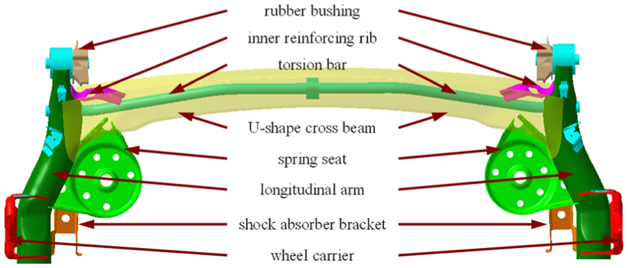
Construction of the rear axle.

Test rig and load-time history of rear axle.
The fatigue critical areas of the rear axle are at the edge on the open side of U-shaped cross beam and in the vicinity of the inner end of the welding seam between the cross beam and reinforcing rib, seen in Figure 3. Two failure criteria are defined for the fatigue test of rear axle: fatigue life to the initiation of a crack with a length of 10 mm, and the feedback forces on the two servo hydraulic actuators drop by 20%. When either of the two criteria is reached, the test stops.

Failure locations on the rear axle.
Approaches for damage accumulation
The fatigue of the rear axle is assessed using the S-N relations together with cycle counting methods and damage accumulation rules. For the cycle counting methods, rain-flow counting method has been proved to a useful one for it can represent the stress–strain hysteresis loop which dominates the damage process.12,13 In this part, other prerequisites for evaluating the fatigue of rear axle, such as derivation of the adopted stress, S-N curve determination, and damage accumulation rules, will be presented. After this, the evaluation of the fatigue life by selected concepts and comparisons with experimental results will be carried out.
Stress for damage calculation
The stress used for the fatigue assessment influences the accuracy of calculated life significantly.14,15 Generally, nominal stress concept, structural stress (local maximum stress at failure locations) concept, and notch stress concept are usually adopted.16–18 As the fatigue crack initiates on the edge of torsion beam, the complex structure and spatial stress condition make nominal stress unsuitable for the situation. Meanwhile, the crack initiates on the edge of the cross beam and propagates toward inner side, which avoids the welding seam, making the notch stress concept not suitable in this case.
The structural stress at failure locations are calculated through finite element analysis (FEA) using commercial software HyperWorks. As the rear axle is made of thin sheet metal components, of which the size in thickness direction is far less than the other two directions, as shown in Table 1, two-dimensional (2D) triangular and quadrangle shell elements are used in the analysis. The normal element size is set to 7 mm and refined according to the geometric features. In the analysis, boundary conditions are the same as that during rig test. The finished model for FEA of rear axle is shown in Figure 4, which includes 49,037 nodes, 43,969 elements. The calculated results of structural stress at failure locations calculated through FEA are verified by monitoring the local strain under test conditions using strain gauges.
Thickness of each component on rear axle.


Model of rear axle for finite element analysis.
Determination of S-N curve
S-N curve is the basis for the fatigue assessment of damage accumulation rules. For the same material, the fatigue strength of the final structure may be affected tremendously by many factors, such as manufacturing process, surface finishing, the size of the critical region, types of loading, and the local stress state originating from the difference in geometric shape.19,20 To avoid this, the S-N curve for fatigue assessment is derived through special designed standard specimens, of which the manufacturing process and surface finishing are the same as that at the failure locations. While the size and load type of the specimen are determined by the stress distribution and stress gradient at the failure locations from the results of FEA as in the next section.
Considering the finite life region is linear in the log–log coordinates, a test method using a minimum sample size of eight is adopted to determine the S-N curve in this region with a reliability of 50%, of which two samples at each of four different levels of stress amplitude. 21 The amplitude and mean value of the stress level are determined referring the rain-flow counting results of the time history at failure locations. The expression and parameters of the S-N relation are regressed by analyzing the test data using least-squares method.
Damage accumulation rules
Five damage models, the PMR, MMR, RMR, DLDR, and DCA, are employed for the fatigue life assessment. These models can be classified into three categories according to the hypothesis of damage accumulation, which are LDA, DLA, and NLA, as schematically shown in Figure 5.

Schematic illustrations of damage accumulation.
PMR is based on the hypothesis of LDA and is the most widely used method for fatigue assessment of structures under variable amplitude loading due to its simplicity (equation (1)). MMR and RMR are also developed on the LDA hypothesis. But the S-N curve is extended after the knee point with a slope k′ = k or a flatter slope k′ = 2k − 1 for the MMR, while the total damage at failure is replaced by an allowable damage Dal = 0.7 for the RMR

where D is the fatigue damage, ni is the number of cycles of ith stress level, r is the number of stress level in the random load history, and Ni is the fatigue life under the corresponding stress level. When D = 1, fatigue failure occurs.
With respect to the DLDR, the fatigue process is divided into two phases and LDA is used in each phase. The fatigue life in Phase I


where


As to the DCA, the fatigue life of structures can be determined by equation (7)

where N is the fatigue life under multi-level stress cycles, σ i is the stress amplitude, αi is the percentage in number of cycles for the ith level stress, σ1 is the maximum stress level, and d is the materials constant and takes a value of 5.8 according to Cretu et al. 14
Results and discussion
Structural stress at failure locations
Figure 6 displays the stress distribution of rear axle under typical load conditions. The maximum stress can be observed at the edge near the welding seam between inner reinforcing rib and the U-shaped torsion beam, which coincides with the failure locations. The stress tensors (Figure 6(c)) indicate a uniaxial stress state at the failure locations. The principal stresses are found parallel to the edge of the torsion beam under all load conditions. The accuracy of the FEA for the rear axle is validated by measuring the strain at the maximum stress point under displacement-controlled torsional load conditions, as shown in Table 2. The relative errors range from 4.8% to 7.0%, showing a good agreement between the calculated and measured strains and thus verified the effectiveness and accuracy of the FEA model. The errors may originate from the angular or position deviation when placing the strain gauges. Based on the stress–displacement relationship, the time history of structural stress at failure locations were determined for the fatigue assessment in the following sections. Also from the size of the area where stress concentration occurred, the width of the specimen was determined and set to 10 mm in the study.
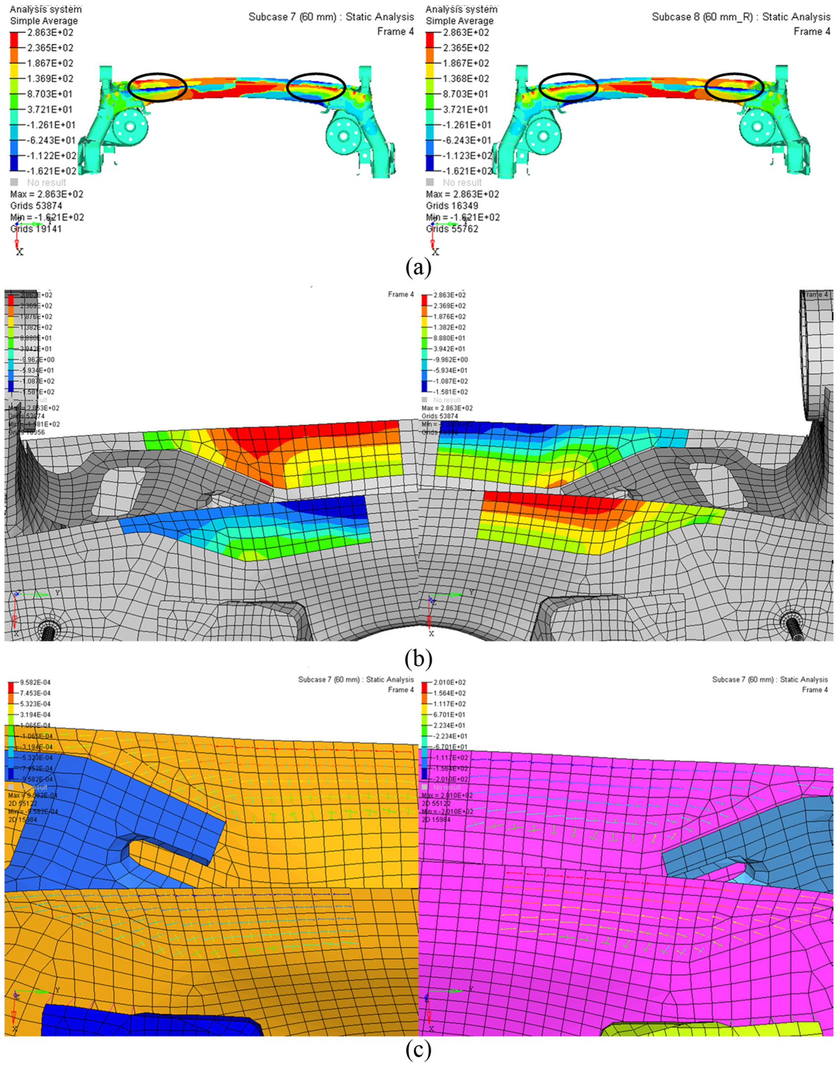
FEA results of rear axle under typical extreme test loading conditions: (a) stress distribution of rear axles, (b) local stress at failure location, and (c) stress tensor at failure location.
Comparison of the strains between the FEA and measured.
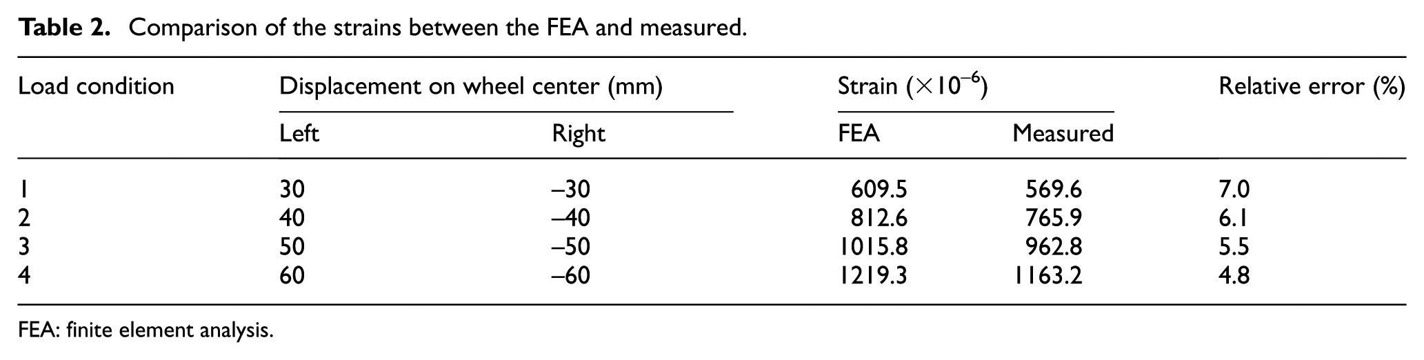
FEA: finite element analysis.
S-N curve and cycle counting
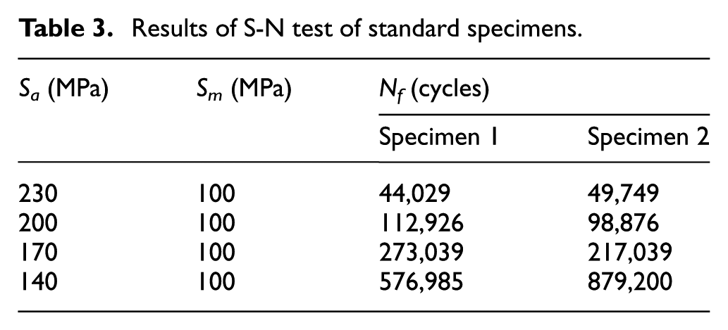
Figure 7 displays the time history of structural stress at failure locations, the rain-flow counting results and the corresponding distribution of cumulative cycle count, the shape of the designed specimen, and the median S-N curve. The structural stress was calculated based on the validated FEA model under test conditions derived from one loop of the test track on proving ground and has a length size Ls = 3.5 × 10⁴ cycles. The S-N curve is regressed by the least-squares method from the results of fatigue test under constant amplitude loads, as shown in Table 3.
Results of S-N test of standard specimens.

S-N curve and cycle counts of structural stress at failure locations.
From rain-flow and cumulative cycle counts, the maximum stress amplitude at failure locations is 225.1 MPa. Thus, the four levels of stress amplitude for the S-N curve test range from 230 to 140 MPa with a common difference of 30 MPa to cover the fatigue damage of the load spectrum. And, a mean value 100 MPa is selected to take into account the mean stress effect, for the variable amplitude structural stress at failure locations fluctuates around 100 MPa as shown in the time history of Figure 8. This can also avoid the bulking of the specimen under compression load. The fatigue limit is taken as the stress amplitude with a fatigue life of 2 × 10⁶ cycles, which is 116.3 MPa according to the S-N relation. Low cycle fatigue region of S-N is estimated using two points; the UTS for 1 cycle and 0.9 UTS for 1000 cycles. 20 For the MMR, which takes into account the loads below the fatigue limit, the S-N curve is extended with a slope of k′ = k and k′ = 2k − 1 for Miner’s and Haibach’s methods, respectively.

Comparison of fatigue lives between calculation and experiments.
Combining the cumulative cycle counts and the S-N curve, it should also be noticed that large proportion of the stress cycles are below the fatigue limit and very few (less than 400) cycles are above it. This emphasizes that the contribution of such small cycles to the fatigue damage should be considered in the fatigue assessment of the rear axle.
Comparison of calculations with experiments
Based on the load spectrum of structural stress at failure locations, the fatigue life of rear axle is estimated according to the damage accumulation rules of PMR, MMR, RMR, DLDR, and DCA. For the PMR, the stress amplitudes below the fatigue limit are ignored. While in the MMR, the S-N curve is extended with a slope k′ = k and a flatter slope k′ = 2k − 1. In the RMR, a damage value 0.7 is selected as the criterion for the fatigue failure. With respect to the DLDR and DCA, the effect of stress amplitudes below the fatigue life is also considered by calculating the fatigue life on two occasions. For one, only the stress amplitudes above the fatigue limit are used (Sa > σ − 1); for the others, all stress amplitudes are used (all).
To validate the calculated fatigue lives, fatigue test of torsion beam rear axle is conducted under the random variable amplitude load spectrum as that shown in Figure 8. Eight specimens were tested to cover the scatter of fatigue life. The calculated lives with different approaches and the experimental lives of rear axle in the form of repetitions of load spectrum are summarized in Figure 8. As the calculations were carried out with the S-N curve for the probability of survival of Ps = 50% (Figure 7), they are compared with the experimental mean value. Also, the 95% confidence interval is plotted to show the probability of the mean value.
The results show that all calculated fatigue lives lie on the safe side, even compared to the lower bound of the confidence interval. And, more conservative calculations are obtained by taking the stress amplitudes below the fatigue limit into account. With the same stress amplitudes, the accuracy of the estimations decreases with the order of the selected damage accumulation rules as PMR, DCA, and DLDR, and the former two rules will lead to close results. As to the MMR, extending the S-N curve with a flatter slope (k′ = 2k − 1) below the fatigue limit will result in a better estimation than with the same slope in the high cycle fatigue region.
In addition to the abovementioned, the results also indicate that the sequence effects and load cycle interaction effects are not obvious in the random variable amplitude load histories, since the calculated fatigue life with DCA and DLDR is of lower accuracy compared to PMR, which ignores the two effects. Therefore, it can be concluded that a LDA hypothesis is good for the estimation of fatigue life under random variable amplitude loads, though it disagrees with the actual physical condition. But considering that the calculations with PMR are too close to the lower bound of the confidence interval and a safe structure must be assured, the MMR with a flatter slope k′ = 2k − 1 is suggested. And, combining with the cumulative failure rate derived from the experimental results of the rear axle, it will result in estimation of fatigue live with a probability of failure around 10%.
Conclusion
In this article, several damage models derived from the linear (PMR, MMR, and RMR), double-linear (DLDR), and non-linear (DCA) damage accumulation hypotheses were discussed for the fatigue assessment of torsion beam rear axle based on the structural stress at failure locations. The major conclusions are as follows:
The applied concepts show similar results. All the calculations with S-N curve for the probability of survival of Ps = 50% are conservative compared to the experimental mean value, even the lower bound of the 95% confidence interval.
The calculated fatigue life with LDA hypothesis is of better estimate, followed by the damage curve approach, and the double-linear rule will result in the most conservative estimation.
More conservative estimations are obtained while conducting the calculations with stress amplitudes below the fatigue limit, and the MMR with a flatter slope (k′ = 2k − 1) below the fatigue limit will lead to reasonable result with a probability of failure around 10%.
In the structural fatigue design, the MMR with a flatter slope based on LDA hypothesis is recommended for the fatigue assessment under random variable amplitude loadings for its acceptable accuracy and failure rate. These conclusions could be helpful for the fatigue assessment and anti-fatigue design of automotive structures.
Footnotes
Handling Editor: Seung-Bok Choi
Declaration of conflicting interests
The author(s) declared no potential conflicts of interest with respect to the research, authorship, and/or publication of this article.
Funding
The author(s) disclosed receipt of the following financial support for the research, authorship, and/or publication of this article: This work was supported by the National Natural Science Foundation of China (Nos 51375313 and 51705322) and SAIC Education Foundation Project (No. 1624).