
Abstract
A serial assistive mechanism was proposed for the hip adduction/abduction and flexion/extension motion assistance, which is kinematically compatible with human hip complex. As the mechanism is connected to the wearer, a 2-degree-of-freedom human–robot closed chain is formed. The closed-form position solution of the assistive mechanism was investigated, the Jacobian matrixes which map the velocity and force from the active joint space of the assistive mechanism to hip joint space were derived, and five new indices for performance evaluation of the assistive mechanism were defined. On the basis of the presented position solution and evaluation indices, the performances of the assistive mechanism during a human gait cycle, such as the human–robot motion offset, the motion and force assistive characteristics, were analyzed through the examples with seven wearing error models. The results show that the assistive mechanism has several distinct advantages including small human–robot motion offset, favorable motion assistive isotropy, and high force assistive efficiency. The proposed indices can evaluate the assistive feature adequately, and the serial assistive mechanism is applicable to the 2-degree-of-freedom hip adduction/abduction and flexion/extension motion assistance.
Introduction
Wearable exoskeletons are mechatronic devices those are worn by individuals to enhance their mobility. This type of device works cooperatively with the human body. According to its application, an exoskeleton can be mainly placed into one of the three categories: the powered exoskeletons for increasing the motion capabilities of healthy persons,1,2 the assistive exoskeletons for elderly or individuals with weak functions affecting their daily lives,3,4 and the rehabilitation exoskeletons for the treatment of nervous, joint, or muscular disease patients.5,6 Currently, as the global population (and particularly, the Chinese population) ages, an increasing number of individuals suffer from mobility difficulties and gait disorders. Walking assistive exoskeletons are regarded as an effective solution to help elderly or disabled individuals regain their functional locomotion and meet the desire to live independently.7–9 Because they are worn by the user and must be designed to facilitate physical human–robot interaction (PHRI), 10 walking assistive exoskeletons should have low inertia, high actuation efficiency, and the ability to smoothly interact with the user. Mechanistic design goals such as light-weight, compact structure, kinematic compatibility,10,11 movement and force transmission characteristics must be prioritized accordingly. Furthermore, the actuation and control of exoskeletons should be able to recognize the implicit motion intention of the wearer; it should allow the wearer full range of normal motion without hindrance and safely provide assistive torque to the wearer’s body.
The hip joint plays an important role in human locomotion and weight support. Its motor function is easily weakened with age or injury due to the substantial load it inherently bears in the body, and impaired hip function has a severe impact on quality of life. A variety of powered hip exoskeletons (PH-EXOS) have been proposed in recent years, for example, Ferris and Lewis 12 established a modified, prefabricated orthosis powered exoskeleton that is driven by artificial pneumatic muscles to assist hip flexion/extension (FL/EX) rotation. The device was designed to align with the wearer’s motion intention through electromyographic (EMG) signals that control the pneumatic muscle actuators. Lewis and Ferris 13 also utilized this type of powered exoskeleton as an experimental platform to test the movement pattern of human hip joints while walking with robotic assistance where the air pressure of artificial muscles is controlled by a footswitch signal. Giovacchini et al.14,15 developed a light-weight active pelvis orthosis (APO) for hip FL/EX assistance. For the purpose of enhancing the kinematic compatibility, the comfort of the PHRI, and the desired dynamic characteristics, the APO was designed with several distinct structural aspects: large carbon-fiber components are used to reduce the inertia, two passive revolute joints are introduced to allow the APO to follow human gait motion out of the sagittal plane, and a novel series elastic actuator (SEA) 16 unit is included to increase the mechanical compliance between the actuators and human–robot interface. The device was also designed with an adaptive control strategy to afford smooth assistive torque on wearer’s hip joints. In the PH-EXOS proposed by Wu et al., 17 a Bowden-cable actuation unit was designed to achieve the mechanical aspects of structural simplicity, light-weight, and flexible driving capability. Two passive joints were added to each branch of the PH-EXOS to improve its kinematic compatibility, and hence passively follow hip adduction/abduction (AB/AD) and internal/external (IN/EX) rotations. In D’Elia et al., 18 an APO was developed, by D’Elia, et al, for 1-degree-of-freedom (DOF) hip FL/EX assistance, in which eight passive joints were introduced to improve the PHRI performance (each branch contains four passive DOFs). In another study, Olivier et al. 19 designed the assistive motorized hip orthosis (AMPO) for assisting sagittal plane motion in the human hip joint. Five passive DOFs were added to minimize the effect of undesired human–robot interactional loads and thereby enhance the PHRI performance of the device. On the basis of the AMPO, two assistive hip orthoses with different actuation mechanisms were proposed, and their technical features were analyzed at length by Olivier et al. 20
As mentioned above, various PH-EXOS have been proposed by the researchers. However, they were mainly designed for the 1-DOF FL/EX assistance. Additionally, less attention has been paid to the position solution and performance evaluation of the exoskeletons, while the mechanistic design goals of the light-weight, compact structure, and kinematic compatibility have been well considered. In this article, a serial assistive mechanism was presented for the AD/AB and FL/EX assistance of human hip joint. This mechanism contains two active and three passive joints and was synthesized by the method proposed previously by Li et al. 21 A 2-DOF human–robot closed chain is formed when the mechanism is connected to the hip complex, in which the undesired human–robot interactional loads caused by axis (or center) misalignment10,22 are reduced due to the presence of passive joints. The structure of the assistive mechanism was described in detail below; additionally, the closed-form position solution of the assistive mechanism was proposed and the Jacobian matrixes which reflect the motion and force mapping relationships between the actuator space of the mechanism and hip joint space were presented. In order to evaluate the assistive performance of the proposed mechanism, five novel indices were defined and the human–robot motion offset, the motion and force assistive features of the assistive mechanism were analyzed accordingly. The results presented here are useful for future dynamics modeling studies, as well as research on wearing comfort and the structural design of the assistive mechanism.
Closed-form position solution of the assistive mechanism
Description of the assistive mechanism
The diagrams of the assistive mechanism, the kinematic model of human hip complex, and the human–robot closed chain are shown in Figure 1. According to anthropotomy, the hip complex is composed of the femoral head, cotyle, ligaments, and the femoral head can only turn in the cotyle freely. 23 Hence, the hip complex can be regarded as a 3-DOF spherical joint S which allows hip FL/EX, AD/AB, and IN/EX rotations. In the serial kinematic chain Ra1Ra2PURc of the hip assistive mechanism shown in Figure 1, Ra1 and Ra2 denote the two active revolute joints with vertical and intersecting axes (the two axes intersect at the hip revolute center Om of the assistive mechanism), Rc is the passive revolute joint connecting the assistive mechanism and the human thigh, and P and U denote the passive prismatic and universal joints, respectively.

Hip assistive mechanism (a), hip kinematic model (b), and human–robot closed chain (c, d).
The motion range and power consumption of hip IN/EX rotation are smaller than those of the FL/EX and AD/AB rotations. IN/EX assistance is not considered here, as it is mainly achieved by the hip complex. Any restriction of the assistive mechanism acting on hip IN/EX rotation should be sequentially removed (as shown in Figure 1). To satisfy this requirement, a feasible structure of the connective joint Rc was proposed, as shown in Figure 2, which is mainly composed of two outer clamping plates installed with the ring slide ways, two inner clamping plates fixed with the ring sliders, and the straps. In addition, in order to prevent undesired human–robot interactional loads caused by axis (or center) misalignment, the human–robot closed chain should have 2 DOFs.

Structure of connective joint Rc.
According to Figure 1(c) and Hunt’s DOF formula, 24 we have
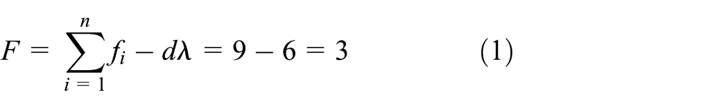
where F denotes the DOF of the human–robot closed chain, n is the number of joints, fi is DOF of the ith joint, λ is the number of independent loops, and d is the dimension of motion space (for spatial chain d = 6).
However, since there is a local DOF around the S and Rc joints, the human–robot closed chain for hip FL/EX and AD/AB motion assistance has 2 DOFs.
Position solution of the assistive mechanism
Consider the human–robot closed chain shown in Figure 1. If the local DOF around the S and Rc joints is removed, the closed chain can be redrawn as shown in Figure 3. Several reference frames (Oh-X0Y0Z0, Oh-xhyhzh, Om-xmymzm, A-x1y1z1, C-x2y2z2, D-x3y3z3, E-x4y4z4, E-x5y5z5, and F-x6y6z6) are defined for the purposes of kinematic analysis. Frames Oh-X0Y0Z0 and Oh-xhyhzh denote the fixed frame and the moveable frame connected to the human thigh, respectively. The origins of these two frames are coincident and assigned at the hip revolute center Oh. Frame Om-xmymzm is fixed on the axis of joint Ra1; its origin is the hip revolute center Om of the assistive mechanism. The wearing error between the assistive mechanism and the hip complex can be described in terms of this frame. Frames A-x1y1z1, C-x2y2z2, D-x3y3z3, E-x4y4z4, E-x5y5z5, and F-x6y6z6 move with the links within the assistive mechanism. Their origins are assigned to the centers A, C, D, E, and F of the Ra1, Ra2, P, U, and Rc joints, respectively.
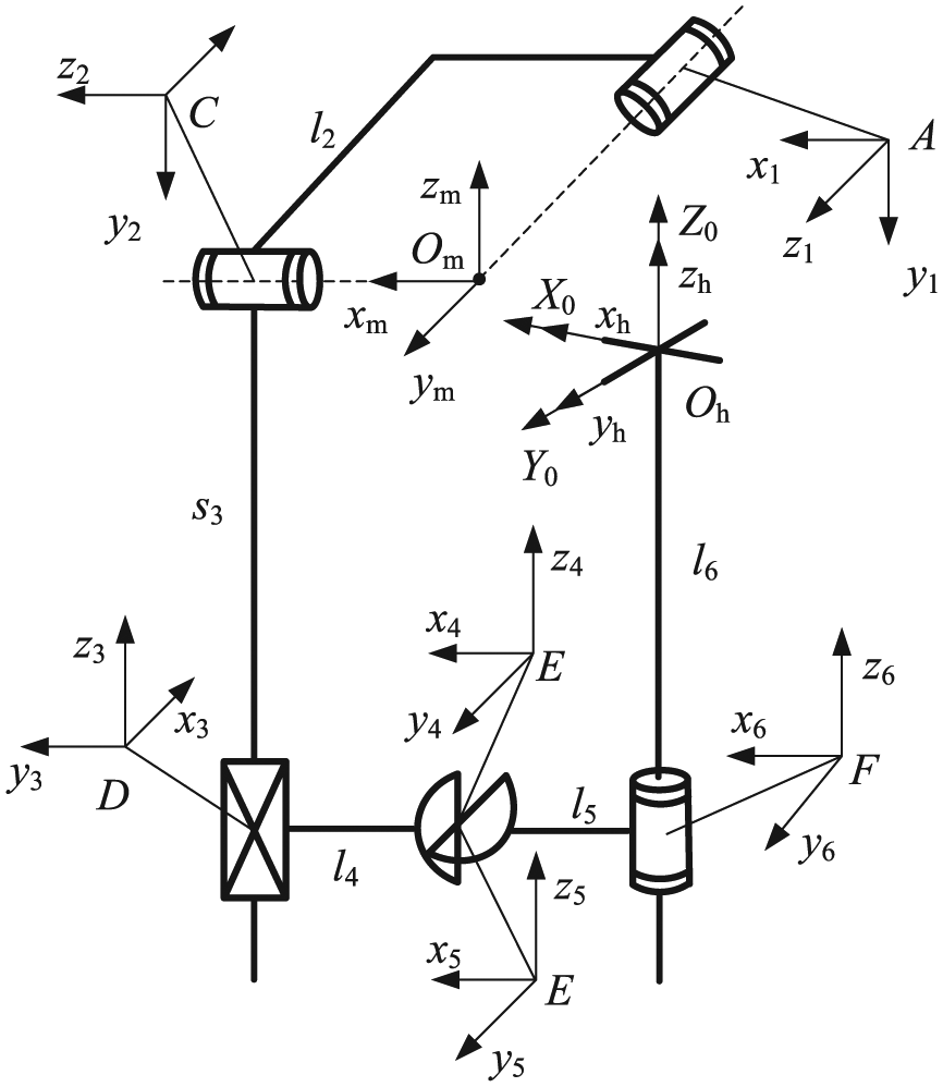
Human–robot closed chain with no local DOF.
Assuming the human–robot closed chain is parted at the center E of the universal joint U, then two serial sub-chains OhOmABCDE and OhFE are obtained. According to the kinematic structure of sub-chain OhOmABCDE, the transformation matrix 0

where 0

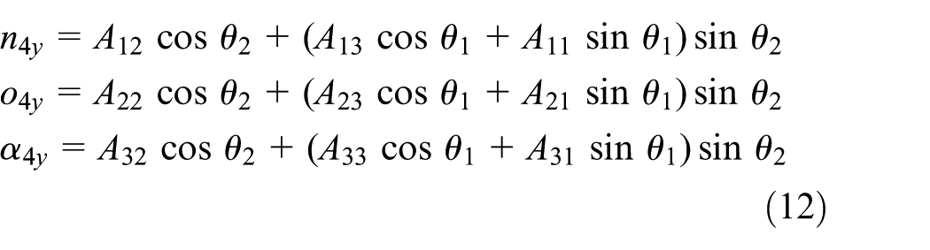
where θ1 and θ2 denote the rotation angles of joints Ra1 and Ra2, s3 indicates the displacement of joint P, and the components Aij (i = 1, 2, 3; j = 1, 2, 3, 4) of matrix 0
Substituting equation (3) into equation (2) yields the following

where (n4xo4xa4x)T, (n4yo4ya4y)T, and (n4zo4za4z)T denote the orientation vectors of the x4, y4, and z4 axes, respectively,
Similarly, according to the structure of sub-chain OhFE, the transformation matrix 0

where 0

where α and β denote the FL/EX and AD/AB rotation angles of the hip joint about axes yh and zh, respectively, and θ6 is the rotation angle of joint Rc. Substituting equation (6) into equation (5) yields

where (n5xo5xa5x)T, (n5yo5ya5y)T, and (n5zo5za5z)T indicate the orientation vectors of the x5, y5, and z5 axes, respectively, and
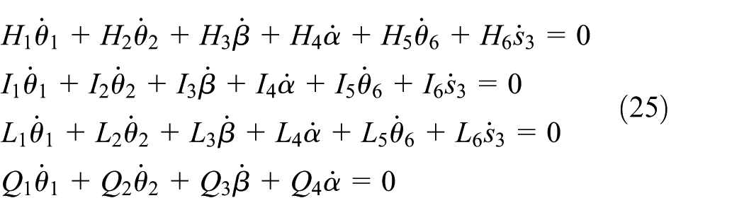
The coordinate values of the center E and the two axes of universal joint U calculated from sub-chains OhOmABCDE and OhFE should be equal and vertical, respectively, so the restriction equations of the human–robot closed chain can be written as follows


where


In equations (10) and (11), the coefficients Ai, Bi, Di (i = 1, 2,…, 6); Ei, Gi (i = 1, 2, 3), and Fi (i = 1, 2) are shown in Appendix 1.
Applying equations (8) and (9) and eliminating variables s3 and


where the coefficients Ki, Vi (i = 1, 2,…, 13) are given in Appendix 1.
Let


Substituting equations (16) and (17) into equations (14) and (15), respectively, yields the following
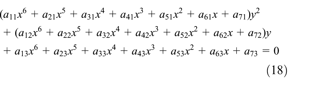

where the coefficients aij, bij (i = 1, 2,…, 7; j = 1, 2, 3) are given in Appendix 1.
By means of equations (18), (19) and eliminating the variable y, the following equation is derived
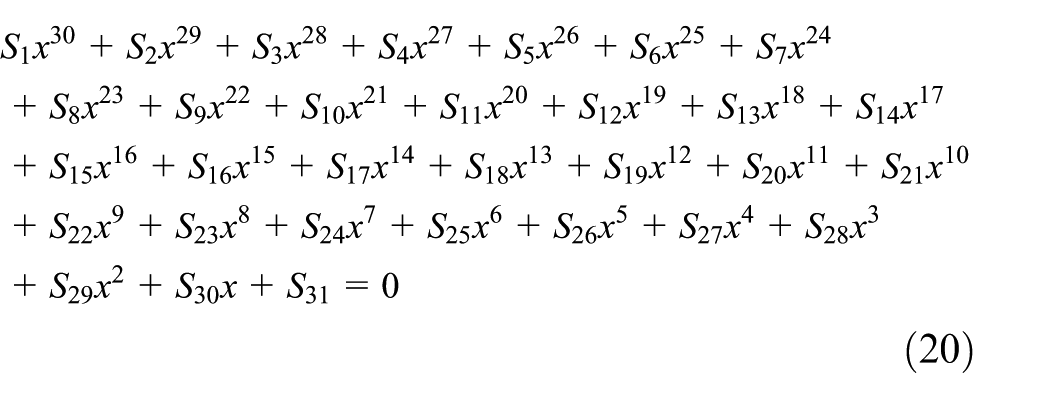
where the coefficients Si (i = 1, 2,…, 31) are presented in Appendix 1.
Equation (20) is a 30th polynomial equation of variable x and its real values correspond to the closed-form solutions of the human–robot closed chain. Once the value of x is obtained, the variables y, θ1, and θ6 can be solved by equations (18), (16), and (17), respectively; then the variables θ2 and s3 can be orderly calculated through equations (9) and (8). The rotation angles of joints θ4 and θ5 of U joint can be solved as follows

where h13, h33, h21, and h22 are the components of matrix
The position analysis of the assistive mechanism is ultimately achieved via the calculations described above. All the joint displacements can be solved when hip FL/EX and AD/AB rotation angles α and β are known.
Solution example of the assistive mechanism
This section presents a position solution example of the assistive mechanism. The FL/EX and AD/AB angle trajectories of the hip joint during a typical gait cycle are adopted as the inputs of the human–robot closed chain and the joint trajectories of the assistive mechanism are solved accordingly.
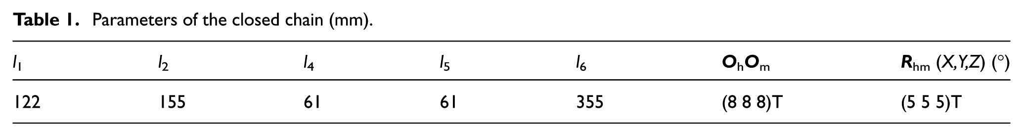
The parameters of the assistive mechanism were all determined by measuring the lower limbs of a volunteer as listed in Table 1. The AD/AB and FL/EX angle trajectories during a typical gait cycle, obtained with a Vicon capturing system by Li et al.,
25
are shown in Figure 4. At the wearing configuration (the volunteer stands naturally), the distance between hip revolute center Oh and the center F of joint Rc is l6 = 355 mm, and the wearing error (the position and orientation errors between frames Oh-XYZ and Om-xmymzm) is supposed to be
Parameters of the closed chain (mm).

Hip motion detection and the joint trajectories during human gait cycle: (a) hip motion detection via a Vicon capturing system, (b) trajectory of AD/AB rotation angle α, and (c) trajectory of FL/EX rotation angle β.

Joint trajectories of the assistive mechanism: (a) trajectory of rotation joint Ra1, (b) trajectory of rotation joint Ra2, (c) trajectory of prismatic joint P, (d) trajectory of the first joint of universal joint U, (e) trajectory of the second joint of universal joint U, and (f) trajectory of rotation joint Rc.
Performance indices of the assistive mechanism
Indices of human–robot motion offset
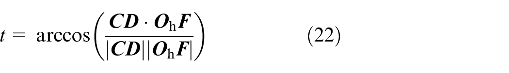
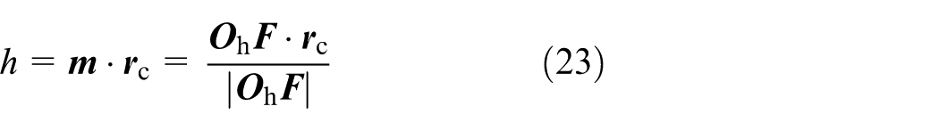
During hip assistance, position and orientation offsets may appear between the wearer’s thigh and the assistive mechanism. These offsets vary with the configuration change of the human–robot closed chain. They are altogether referred to here as the “human–robot motion offset” of the assistive mechanism. To describe and evaluate the influence of wearing error on motion offset, three indices are defined as shown in Figure 6, where h denotes the distance between the center C of joint Ra1 and the center Oh of hip joint along the axis direction of human thigh, t indicates the intersecting angle between the thigh of the assistive mechanism and human thigh, and l is the difference of lc (distance between the two thighs) and (l4 + l5) (distance between the two thighs with no wearing error).

Indices of human–robot motion offset.
According to Figure 6 and the definitions of t, h, and l, the three indices can be expressed as follows
where
where

where
Jacobian matrices, assistive isotropy, and assistive efficiency
In order to evaluate the performance of the robots working with an end-effector, various capability indices such as the dexterity measure, minimum singular value, condition number, and manipulability (velocity or force) ellipsoid are typically utilized. These indices can all be defined based on the Jacobian matrixes that map the motion and force from a robotic joint (actuator) space to the Cartesian (end-effector) space.26–28 In recent studies, these indices are also used to evaluate the performance of wearable exoskeletons.29–33 It is worth to note that unlike end-effector manipulation robots, the task space of an exoskeleton corresponds to the joint space of the human body, and the motion and force are required to be transferred from the active joint space of the exoskeleton to the wearer’s joint space. Hence, it is suitable to define the evaluation indices on the basis of the matrices which reflect the motion and force mapping relationships between the two joint spaces. With this consideration, the velocity and force Jacobian matrices of the assistive mechanism are derived, and two evaluation indices, that is, the assistive isotropy da and assistive efficiency ea, are proposed in this section.
Differentiating equations (8) and (9) yields the following
where
The velocity relationship between the two joint spaces can then be expressed as follows

where
By applying the virtual work principle, the force relation between the two joint spaces can be written as

where τ1 and τ2 denote the driving torques of joints Ra1 and Ra2, τα and τβ denote the torques acting on hip AD/AB and FL/EX revolute axes, and
By defining the manipulability ellipsoid proposed by Yoshikawa,
26
a velocity super-circumference
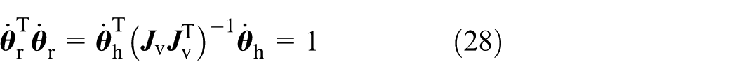
where
According to the meaning of the velocity ellipsoid, 26 it is known that at a certain movement configuration of the human–robot closed chain, the hip joint gets the greatest (or least) rotation dexterity along the long (or short) principal axis direction of the velocity ellipse. If the velocity ellipse approximates to a circumference, the hip joint gets almost the same rotation dexterity along all directions. Such a movement configuration can be referred to as the isotropic assistive configuration. To describe and evaluate the mechanism’s performance accordingly, motion assistive isotropy index da is defined as follows

where llp and lsp denote the lengths of the long and short principal axes of the velocity ellipse (correspond to the reciprocal of the square root of the minimal and maximal eigenvalues of matrix
The force transmission ratio is another important performance indicator in addition to the motion assistive characteristics, as sufficient torque is critical for providing the hip joint with effective motion assistance. Analogous to the velocity ellipse, a force ellipse can be defined as follows
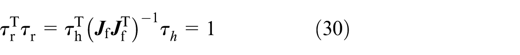
where
According to Chiu
34
and Kim and Choi,
35
it is known that at a certain movement configuration of the human–robot closed chain, the force transmission ratio along a particular direction is equal to the distance from the center to the surface of the force ellipse along the directional vector. Hence, a larger minimum force transmission ratio indicates that the assistive mechanism is at a motion configuration with higher force assistive efficiency. Accordingly, half of the length of the short principal axis of the force ellipse (equal to the minimum singular value of the matrix

where
Performance analysis of the assistive mechanism
The performance of the serial hip assistive mechanism is analyzed as described below by evaluating its human–robot motion offset, motion assistive isotropy, and force assistive efficiency during a typical human gait cycle. During these investigations, the dimensional parameters given in Table 1 are adopted and seven wearing error models are tested to ensure a thorough analysis.
Motion offset analysis
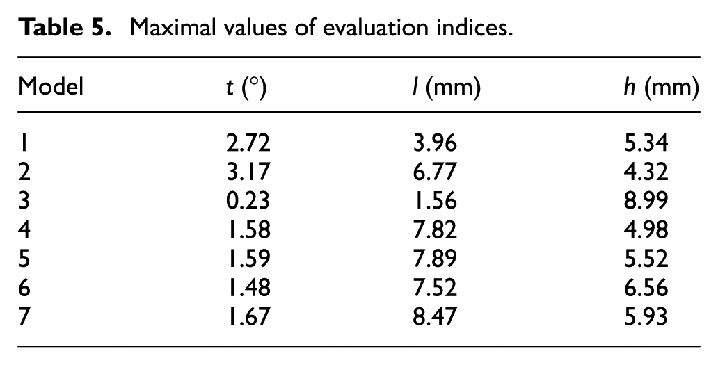
After applying the position solution proposed in section “Closed-form position solution of the assistive mechanism,” the initial joint displacements and the initial values of indices t, h, l of the assistive mechanism corresponding to the seven wearing error models (Table 2) are calculated as provided in Tables 3 and 4. The value trajectories and maximal/minimal values of t, h, l during one gait cycle are also solved as shown in Figure 7 and Tables 5 and 6. In Figure 7, the trajectories marked by numbers 1, 2,…, 7 correspond to wearing error models 1, 2,…, 7, respectively.
Parameters of seven wearing error models.

Initial displacements of mechanism’s joints.

Initial values of evaluation indices.

Maximal values of evaluation indices.
Minimal values of evaluation indices.


Value trajectories of indices t, h, and l: (a) value trajectories of index t, (b) value trajectories of index h, and (c) value trajectories of index l.
According to the results provided in Tables 3–6 and Figure 7, the motion offsets between the mechanism’s thigh and the wearer’s thigh are sufficiently small and the value ranges of indices t, h, and l correspond to t ∈ (0.01 3.17) (°), h ∈ (1.42 8.99) (mm), and l ∈ (–0.81 8.47) (mm), respectively. In addition, the motion offset is found to be affected substantially by the wearing error: for instance, the motion offsets corresponding to the wearing error models 2 and 3 are quite different. Minimizing wearing error is a crucial consideration as the assistive mechanism is connected to the human hip complex.
Assistive isotropy and assistive efficiency analysis
The assistive isotropy and assistive efficiency of the assistive mechanism during a typical gait cycle are analyzed extensively by means of indices da, ea, and the seven wearing error models described above. Variations in the value of index da, the shape of the velocity ellipse (corresponding to wearing error model 7), and the value of index ea are shown in Figures 8–10, respectively. As shown in Figure 8, the minimal value of index da is 0.9422 and the range of index da is da ∈ (0.9422 0.9971) under the seven wearing error models. As shown in Figure 9, all of the velocity ellipses at 0%, 25%, 50%, and 75% gait cycle approximate to a circumference corresponding to wearing error model 7 (although similar cases appeared for other models). These results indicate that the assistive mechanism has fine motion assistive isotropy during the human gait cycle. In addition, as shown in Figure 10, the minimal value of index ea equals 0.9750—sufficiently large to confirm that the assistive mechanism achieves high force efficiency during hip AD/AB and FL/EX assistance.

Values trajectories of index da.
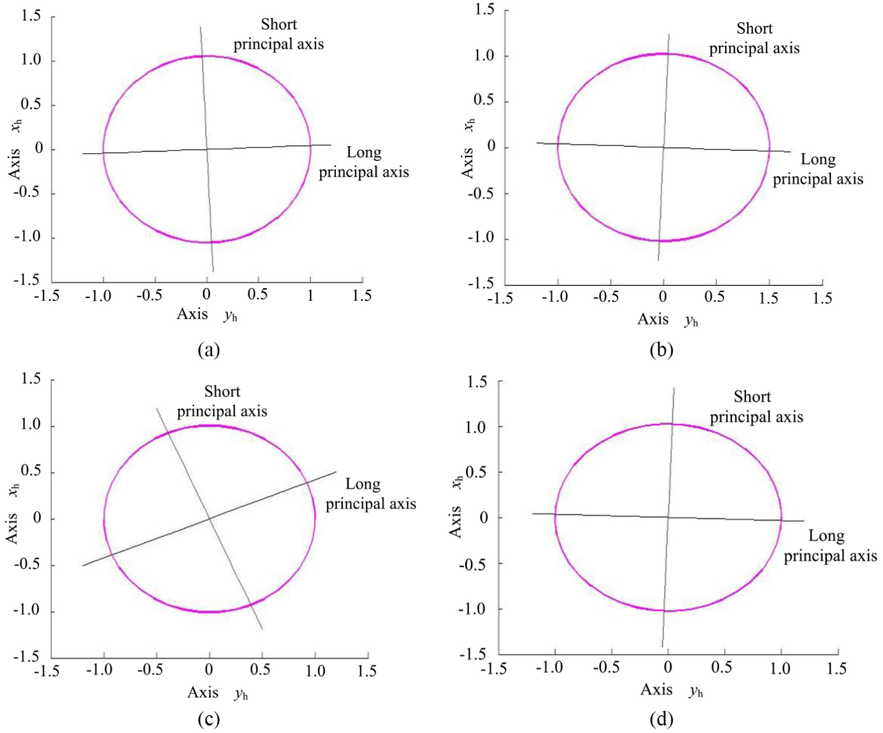
Shape variation of velocity ellipses during human gait: (a) 0% gait cycle (llp = 2.1068, lsp = 2.0006); (b) 25% gait cycle (llp = 2.0454, lsp = 1.9994); (c) 50% gait cycle (llp = 2.0102, lsp = 1.9974); and (d) 75% gait cycle (llp = 2.0474, lsp = 1.9992).

Values trajectories of index ea.
Discussion
In this section, the performances of the hip assistive mechanism were evaluated, the results indicate that during a human gait cycle, the motion offset between human and mechanism’s thighs is small; the assistive mechanism has fine motion assistive isotropy and high force assistive efficiency. However, it should be highlighted that in this study, the hip FL/EX and AD/AB motion patterns were obtained from a single healthy subject than the elderly people, the wearing error models may not be sufficient (e.g. the translation component of a single axis may be up to 20 mm), and these issues would generate different analysis results. On the other hand, the assistive mechanism should be safe and able to guarantee its functionality. Specifically, the blockage of the mechanism should not take place during hip motion assistance, and the abnormal human range of motion must be avoided. With these considerations, future work will focus on the experimental detection of the typical gait alteration patterns of elderly people and the suitable magnitudes and configurations of wearing error. Furthermore, to reduce the risks of the blockage of the assistive mechanism and the abnormal human range of motion, in the mechanistic design of the hip assistive mechanism, the light-weight spin and slip bearings would be considered in the design of the passive joints to reduce undesired friction (hence to reduce the blockage of the mechanism), and the limit strokes of the joint actuators would be determined through the kinematic simulation of the human–robot closed chain during typical gait cycles (hence to reduce the risk of the abnormal human range of motion).
Conclusion
A serial assistive mechanism was proposed on the basis of the motion feature analysis of human hip joint and the DOF theory of the spatial closed-loop mechanisms, which is kinematically compatible with the human hip complex and suitable for the 2-DOF hip AD/AB and FL/EX motion assistance.
The closed-form position solution of the assistive mechanism was proposed, the Jacobian matrices mapping the velocity and force from the active joint space of the assistive mechanism to hip joint space were derived, and five evaluation indices for performance of the assistive mechanism were defined.
The motion and force assistive performances of the hip assistive mechanism were evaluated, the results indicate that during a human gait cycle, the motion offset between human and mechanism’s thighs is small, and the assistive mechanism has fine motion assistive isotropy and high force assistive efficiency.
Footnotes
Appendix 1
Handling Editor: Francesco Aggogeri
Declaration of conflicting interests
The author(s) declared no potential conflicts of interest with respect to the research, authorship, and/or publication of this article.
Funding
The author(s) disclosed receipt of the following financial support for the research, authorship, and/or publication of this article: This work was supported by the National Natural Science Foundation of China under grant nos 51675008, 51705007; the Natural Science Foundation of Beijing Municipality under grant nos 3171001, 17L20019; and the Beijing Technology program under grant no. Z161100001516004.