
Abstract
The fit clearance between the spool and the sleeve has important influences on the performance of the proportional cartridge valve. Too small clearance will cause jam and too much clearance will increase leakage. Therefore, under the precondition of no sticking, the smaller the clearance, the better the performance. The minimum fit clearance is affected by two factors, the machining accuracy and the structure deformation. The structure deformation is related to the working condition and the structure of valve. It is costly and takes much more time to optimize the fit clearance by the trial and error method. According to a specific working condition, the sleeve deformation of a proportional cartridge valve with an 80-mm port is evaluated by the three-dimensional finite element simulation. A series of experiments are carried out under the different fit clearances and the different pressures. The comparison between the simulation results and the experimental results shows that the sleeve deformation under pressure is the decisive factor to optimize the fit clearance of the proportional cartridge valve, and the finite element simulation accuracy can meet the engineering requirements for optimizing the fit clearance.
Keywords
Introduction
A proportional cartridge valve is mainly used in the electrohydraulic control system of the large mechanical equipment such as forging presses, die-casting machines, and hydraulic presses, which is the key component to achieve rapid and steady performances of hydraulic systems.1–3 The determination of the fit clearance between spool and sleeve is one of the major sticking points during the design and manufacture of proportional cartridge valve. Undersize clearance could cause the spool creeping, whereas oversize clearance will lead to too much leakage to achieve the control performance of small flow rate. On the other hand, the fit clearance also regards to the efficiency and cost of manufacture, so a reasonable fit clearance is important. The machining accuracy and the structure deformation caused by pressure are the most important factors which the fit clearance is decided by. Traditionally, the optimum fit clearance is got by the trial and error method which is costly and takes much more time. In this article, the three-dimensional (3D) finite element simulation is used to evaluate the structure deformation of a proportional cartridge valve with an 80-mm port.
Computational fluid dynamics (CFD) is becoming a good tool in the analysis and design of hydraulic valve, since it can give a clear insight into the distribution of pressure and velocity. The pioneering applications of CFD to the analysis of hydraulic components have been done by many investigators. A comparison between experimental and numerical data for an open-center directional control valve, performed by Amirante et al.,4,5 has confirmed the good accuracy of the CFD predictions in terms of forces evaluation. Bordovsky et al. 6 emphasized the importance of experiments by their research in which the simulated values of axial forces are in average by 32% lower compared with the measured ones because the CFD simulations may neglect the potential uncertainty. Lisowski et al.7,8 proposed solutions to reduce significantly the pressure losses and flow forces using CFD method, and the simulation results were verified through experiments. Beune et al. 9 analyzed the opening characteristic of high-pressure safety valves with fluid–structure interaction (FSI) and use the FSI multi-mesh method to investigate the sensitivity of valve dynamics. Lin et al. 10 used an energy recovery unit to reduce the overflow loss and investigated its effect on the pressure control characteristics and steady-state flow force of the pilot proportional relief valve through CFD simulation and experimental analysis. To improve the proportional spool valve’s hydraulic performance, Frosina et al. 11 proposed a mathematical solution to minimize the spool spin effect with a 3D CFD method. Qian et al. 12 employed the CFD method to explain the dynamic flow characteristics of the pilot-control global valve. Song et al. 13 used the moving mesh to investigate the fluid and dynamic characteristics of a direct-operated safety relieve valve. Liu et al. 14 comprehensively considered the effect of the pressure, temperature, and valve structure dimensions on the fit clearance of large-diameter slide valves. Deng et al. 15 evaluated the viscous heating-induced jam fault of a valve spool through fluid–structure coupling simulations and obtained the deformation of spool. Wei et al. 16 analyzed, in detail, the maximum pressure difference in fit clearance at the two sides of eccentric spool with number of compensating grooves and then discussed the leakage through the fit clearance. Zhou et al. 17 found the energy loss of control valve through an analysis of the numerical simulation results and proposed the optimization plan. Zhe et al. 18 studied the effects of valve plug on the throttling features of globe control valve by the CFD simulation and experiment. Zhao et al. 19 analyzed the heat-fluid-solid coupling of double flapper-nozzle servo valve using the finite element simulation and experiment. Huang et al. 20 analyzed the flow field of piezoelectric pump by the finite element method, and its export flow rate is predicted by numerical simulation. Moreover, some scholars also studied the properties of cartridge valve in some application areas. The relationship between transient flow force acting on the valve cone and the discharge coefficient to the flow and valve displacement during closing and opening of valves are obtained by Zheng et al. 21 through the CFD simulation. Sun and Chen, 22 using FSI, explained the instantaneous mechanical behavior of cartridge valve during the unloading of ejecting press. Zhou et al. 23 discussed the relation between structure reliability allowance and width dimension concerning cartridge valve through the 3D stable thermal structure coupling simulation. However, the research on the sleeve deformation caused by the pressure field in the active control cartridge valve and the optimization of the fit clearance by the CFD simulation is rare. In this article, by establishing the FSI model of an active control proportional cartridge valve, the distribution of the sleeve deformation is evaluated and then the fit clearance between sleeve and spool is optimized. Finally, a set of experiments are carried out to verify the simulation results.
Structure and principle of cartridge valve
The principle and structure of a proportional cartridge valve are shown in Figure 1. The cartridge valve has two control chambers. There are three dynamic sealing rings among the upper sections of spool, sleeve, and cover. The fit clearances in the upper sections are large and are decided by the specification of dynamic sealing rings. The lower sections of spool, including the leading section and the orifice section, require a small fit tolerance to obtain high control accuracy. The fit clearances in the lower sections must be designed carefully to avoid jam fault.

Structure and principle of proportional cartridge valve: (a) principle and (b) structure.
In the leading section, the pressures on the sleeve are always balanced due to the hole in the guide screw. So, the sleeve deformation is negligible in the leading section. As far as the spool is concerned, there are two cases that need to be discussed as following. When the oil flows from the port B to the port A, the spool shrinks under pressure, which is helpful to avoid jam fault. 24 When the oil flows from the port A to the port B, the spool expands under pressure, which can lead to jam fault. In this case, the spool deformation should be taken into account in the design of fit clearance.
In the orifice section, the pressures on the spool are always balanced. So, the spool deformation is negligible in the orifice section. As far as the sleeve is concerned, there are two cases that need to be discussed as follows. When the oil flows from the port A to the port B, the sleeve expands under pressure, which is helpful to avoid jam fault. When the oil flows from the port B to the port A, the sleeve shrinks under pressure. In this case, the sleeve deformation should be taken into account in the design of deciding the fit clearance.
In this article, the flow direction from the port B to the port A is assumed. According to the above discussion, only the sleeve deformation under pressure in the orifice section needs to be considered in the design of fit clearance.
FSI model and simulation analysis
FSI model
The FSI model of a proportional cartridge valve is established as shown in Figure 2, and the simulation parameters are shown in Table 1. FSI analysis refers to the interactions of fluid field and structure field when performing analysis. This article adopts the one-way coupling analysis and only focuses on the effect of fluid field on solid structure. 25

FSI model of proportional cartridge valve: (a) model structure and (b) deformation distribution of sleeve.
Parameters of structure and material.

According to the analytical procedures, first, the fluid field simulation is carried out by the Fluent software. The blue area in Figure 2(a) represents the fluid field. The fluid is assumed to be Newtonian and incompressible, which is free of the temperature field. The pressures on the port A and the port B are treated as the known boundary condition. The orifice size is a variable structure parameter. The standard k-ε turbulence model is used for the flow rate is high in the case of small orifice size. The fluid field simulation was performed by the numerical solution of the incompressible Navier–Stokes equations.26,27 Iterative residual value is set less than 1e–3. A variety of mesh generation methods are used to refine the model.
Second, the finite element model of sleeve is established by ANSYS, and the pressure field obtained by the fluid field simulation is imported as the loading condition. The pressures of control chambers are the known parameters and treated as one of the loading conditions of the structure field simulation. The load type is set to be static structural. The fixed constrain is applied to the top section of the sleeve. The deformation analysis of the sleeve is performed by ANSYS, and the simulation result is shown in Figure 2(b).
Simulation analysis
Based on the simulation model, considering the influences of valve opening and port pressure, the amount and distribution of the sleeve deformation are studied. The simulation result shown in Figure 3 is obtained when the port B pressure is 30 MPa and the port A pressure is 0.1 MPa, which shows the influences of the valve opening on the maximum deformation and its location. As shown in Figure 3(a), the maximum deformation of the valve sleeve is about 0.02 mm, and the variation of the maximum deformation with the valve opening is about 10% (0.002 mm). The distribution law of the sleeve deformation is consistent with the analysis of the structural principle. The maximum sleeve deformation occurs at the orifice fitting section as shown in Figure 4 and is less affected by the valve opening as shown in Figure 3(b). The maximum deformation is proportional to the pressure at the port B (Figure 5).

Relation between deformation and displacement: (a) maximum deformation and (b) location of maximum deformation.
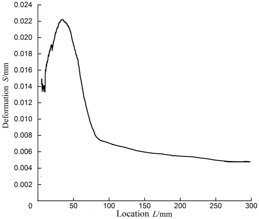
Distribution of sleeve deformation.

Relation between deformation and pressure.
Experiment and analysis
Experimental bench
Hydraulic schematic diagram of experimental bench is shown in Figure 6. The port B of proportional cartridge valve ① is connected to the rod chamber of cylinder while the port A is connected to the tank. When the hydraulic cylinder extends out, the proportional cartridge valve ① controls the output flow of the rod cavity. The piston accumulator ③, whose initial gas pressure is 12 MPa, provides enough flow to the non-rod cavity of cylinder via the cartridge valve ②. The pressure at the port B of the proportional cartridge valve can be adjusted by adjusting the opening of the cartridge valve ② manually. After the cylinder moves to the left end, the direction valve ⑤ switches to the right side so that the cylinder returns to the right end and the next test can be carried out. The test procedure is as follows. First, the accumulator is charged to a certain pressure through the check valve ④. Second, the cartridge valve ② is opened. Third, a test signal is applied to the proportional cartridge valve ①, and its spool displacement is acquired by the displacement sensor.

Hydraulic system diagram of experimental bench.
To verify the simulation results, the four spools with different fit clearances as shown in Table 2 are manufactured. The two sets of experiments are separately carried out. The first set of experiments is carried out for the four valves with the same pressure of 30 MPa. The second set of experiments is carried out for the valve 1# with the different pressures. The performance of feedback signal tracking command signal can determine whether there is the jam phenomenon.
Fit clearances of tested valves mm.

Experimental results and analysis
Figure 7 shows the experimental results of four valves with the same pressure of 30 MPa at the port B. It could be seen that the spool can track the command signal smoothly when the fit clearance is greater than 0.02 mm. According to the foregoing simulation shown in Figure 3(a), the sleeve deformation is also 0.02 mm when the pressure is 30 MPa. Meanwhile, the creeping phenomenon appearing in the experiment results of spools 1# and 2# can be interpreted as the result of the sleeve deformation exceeding the fit clearance.

The effect of fit clearance on movement performance: (a) spool 1#, (b) spool 2#, (c) spool 3#, and (d) spool 4#.
Due to the machining accuracy limit, we do not have enough spools to verify that 0.02 mm is the best fit clearance. So, the second set of experiments is carried out for the spool 1# under different pressures at the port B. The experimental results are shown in Figure 8. It could be seen that the spool 1# can smoothly track the command signal as long as the pressure is below 13 MPa. On the other hand, according to the foregoing simulation shown in Figure 5, the sleeve deformation under the pressure of 13 MPa is 0.009 mm, which is less than the fit clearance of spool 1#, 0.01 mm. This set of experiments further confirms that the sleeve deformation is the decisive factor to determine the optimum fit clearance of the proportional cartridge valve, and the finite element simulation accuracy can meet the engineering requirements.
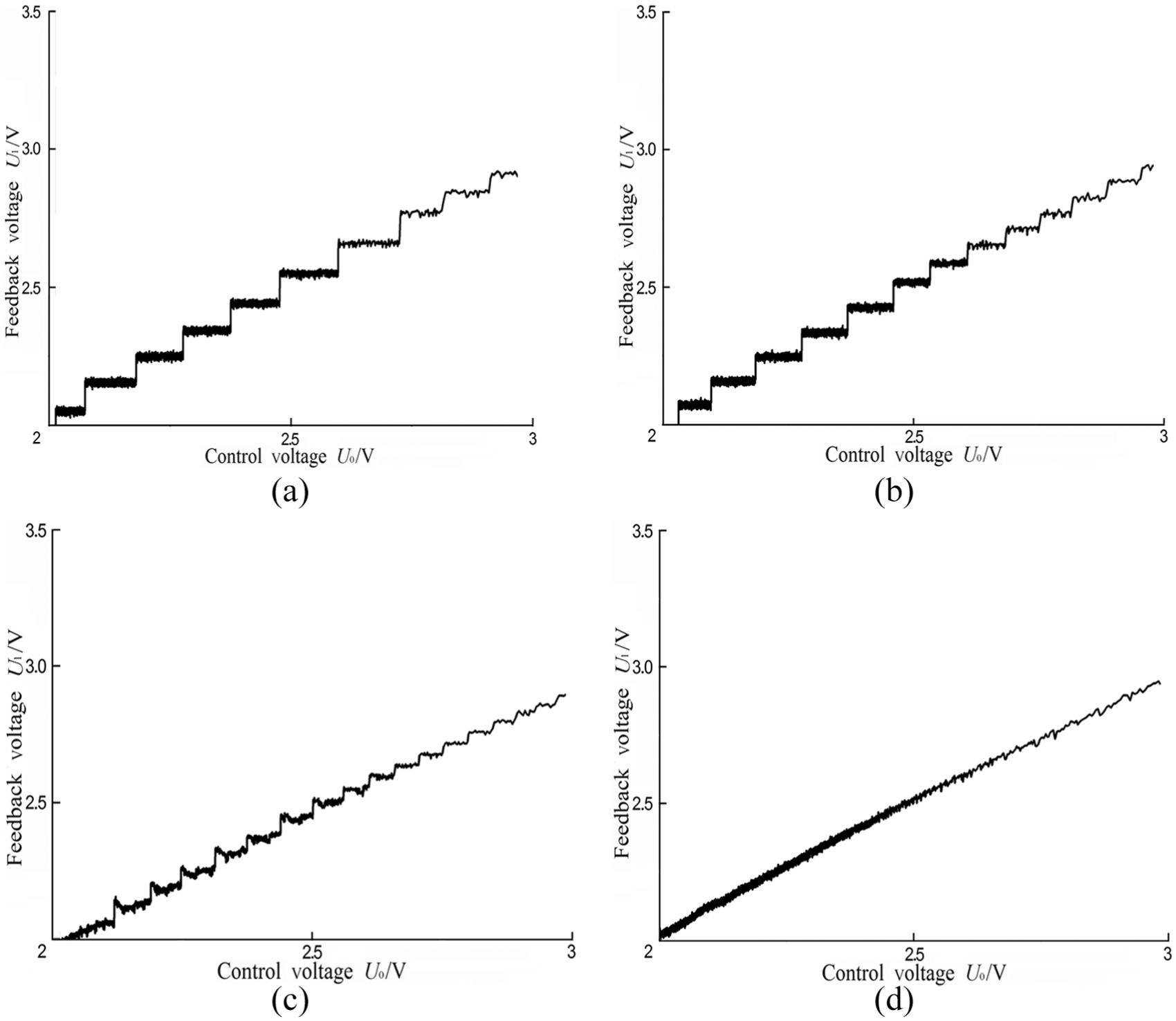
The effect of pressure on movement performance: (a) performance under 16.5 MPa, (b) performance under 15 MPa, (c) performance under 14.2 MPa, and (d) performance under 13 MPa.
Conclusion
Through the comparison between simulation and experiment, the following conclusions are obtained:
The sleeve deformation under pressure is the decisive factor to optimize the fit clearance of the proportional cartridge valve.
The finite element simulation accuracy of sleeve deformation under pressure can meet the engineering requirements for optimizing the fit clearance of proportional cartridge valve.
Footnotes
Handling Editor: Kai Bao
Declaration of conflicting interests
The author(s) declared no potential conflicts of interest with respect to the research, authorship, and/or publication of this article.
Funding
The author(s) disclosed receipt of the following financial support for the research, authorship, and/or publication of this article: This work was supported by the Science Fund for Creative Research Groups of National Natural Science Foundation of China (grant no. 51221004), National Natural Science Foundation of China (grant no. 50805127), and Professional Development Program of Higher School Visiting Scholar (grant no. FX2014079).