
Abstract
The seal is a critical component of a cone bit, whose performance can be reduced because of its large contact area. To reduce stress within the seal, a bionic nonsmooth surface seal was designed and the structural parameters of sealing rings with spherical and conical teeth were determined. The sealing performances of the sealing rings with spherical and conical teeth were analyzed and compared using finite element analysis. Comparisons were made between the sealing performances of the newly designed rings and currently available sealing rings. Finite element analysis was performed based on a constitutive model of the rubber material used and contact theory. The stress, strain, and contact pressure distributions were analyzed. Uneven stress, strain, and contact pressure distributions with high values occurred on the sealing ring with spherical teeth. The sealing ring with conical teeth was selected because of its improved sealing performance. Compared with currently available sealing rings, the stress and contact pressure distributions of the newly designed sealing ring were both uniform and reasonable, and the stress and contact pressure levels were reduced.
Introduction
Millions of cone bits are consumed globally every year. Serious bit failures can cause significant economic losses and have led to numerous safety incidents. According to field data, one of the main causes of cone bit failure is early bearing failure, which accounts for approximately 80% of cone bit failures. Seal failures lead to bearing wear and cause approximately 30% of bearing failures.1–6 The main cause of seal failure is the high frictional force and associated heat that results from the seal’s large contact area. Seal failure can be very serious, particularly under high temperature and pressure conditions. Therefore, studies to determine a new type of seal structure that combines a smaller contact area with excellent sealing performance are necessary.
Nonsmooth biological surfaces exist in nature, and a variety of surface forms have evolved to adapt to different living environments in the land, sea, or sky. Bionic nonsmooth surfaces are suitable for use in contact interfaces with relative motion because of their drag reduction, anti-adhesion, and wear resistance characteristics. Bionic nonsmooth surfaces have been applied extensively in oil exploration, machinery, and various other fields. 7
Ren et al.8,9 studied the drag reduction performance of the bionic nonsmooth surface of a bulldozer blade that was based on the geometric nonsmooth structures of insects such as cockroaches and ants. Compared with traditional smooth surface blades, the drag of the blade with the nonsmooth surface was reduced by 13.02%. In 2009, Gao et al. 10 researched bit design based on bionic nonsmooth theory and developed a bionic diamond bit. The operating speed and lifetime of this bionic bit were improved by 44% and 74%, respectively, compared with the conventional bit performance. In 2009, Lu et al. 11 researched the mechanical properties and microstructure of a bionic nonsmooth stainless steel surface and found that the residual stress, wear resistance, and other mechanical properties of the surface were improved significantly. Limited research has been carried out to date on bionic nonsmooth surface seals for cone bits.12–22 The aims of this work were to design a new type of bionic seal, to analyze the stress, strain, and contact pressure distributions of the seal through finite element analysis (FEA), and to study the sealing performance of the proposed seal and establish its potential advantages and reliability compared with existing seals.
Structural design
Figure 1 shows the proposed bionic nonsmooth surface seal structure in a chamber located between the roller and the bearing. The bulges on the inner and outer rings are similar in shape (i.e. spherical and conical) to animal teeth and are arranged in a staggered manner to improve the strength and toughness of the seal. Selected dimensions of the two types of teeth are shown in Figure 2.

Bionic nonsmooth surface seal structure: (a) cone bit and (b) seal.

Selected dimensions of the two types of teeth: (a) seal ring structure, (b) sealing ring with spherical teeth, and (c) sealing ring with conical teeth.
Constitutive model of the rubber material
Rubber is a hyperelastic material with characteristics that include high deformation, nonlinearity, high elasticity, isotropicity, and incompressibility. 23 A constitutive model is thus essential for FEA of rubber components. To define the hyperelastic material behavior, a constitutive relationship and experimental data are required to determine the material’s parameters. Constitutive models of rubber include the neo-Hookean strain energy function, the exponential-hyperbolic rule, the Mooney–Rivlin (M-R) model, the Klosenr–Segal model, and the Ogden–Tschoegl model. The M-R model has been widely used in many research studies,20–22 and so this model was used here. The model function can be expressed as 24

where


In the uniaxial stress state,

where
We use five parameters to obtain the quadratic shown in equation (6)

A five-parameter equation is used in our study. The stress–strain relationship of the material can be obtained from the results of compression experiments. 25 The material parameters are given in Table 1.
Material parameters.
FEA
Finite element model
Geometric model
Because the force and the structure of the new seal design are both axisymmetric, a two-dimensional (2D) axisymmetric model is used. The cone and the bearing are both steel components and thus their deformation can be ignored.
Unit properties
Because the cone and the bearing are steel components, a 2D eight-node PLANE 183 unit (eight-node 183) was chosen. A 2D eight-node hyperelastic element (Hyper 74) is chosen for the sealing ring because it is made of rubber.
Grid division
Because the stress analysis of the rubber ring is the most important aspect of the analysis, its mesh is small and dense at a mesh size of 0.2 mm, while the mesh sizes of the cone and the bearing are larger at 0.5 mm. The mesh shapes are triangular and quadrilateral. The higher quadrilateral grid stability produces more accurate analytical results and thus, a quadrilateral mesh is chosen.
Basic theory of the contact problem
Correct analysis of a contact problem is important. From a mechanical perspective, a contact problem is a complex problem with highly nonlinear boundary conditions, and it is necessary to track the motions of multiple objects accurately before contact and interaction occur between these objects. After contact occurs, an appropriate and efficient contact method must be used. The contact problem is usually solved using a combination of direct contact methods, a Lagrange multiplier, and a penalty function. The contact problem of the proposed seal structure includes factors such as high deformation, material nonlinearity, and geometrical nonlinearity.
The basic idea of the penalty function is to connect the constraint conditions with the objective function using a penalty factor. The penalty function does not change the order of the system equation, and the positive symmetry of the stiffness matrix cannot be changed, which means that the penalty function is easier to solve. The penalty function method is applied to determine the design parameters.
The penalty function is given as follows. In a region

where
The cone and bearing are made from steel, and the sealing ring is made from rubber. Therefore, the contact is a rigid-flexible type contact. The contact structure is axially symmetrical. Two contact pairs exist between (1) the sealing ring and the cone bore and (2) the sealing ring and the bearing. A penalty function equation is used. 26
Loads and boundary conditions
Because the section widths of the sealing rings with the spherical and conical teeth are the same, their displacements are also the same. The simulation can thus be separated into the following steps: (1) a full displacement constraint is applied to the bearing; (2) a radical displacement constraint is applied to the cone, where the displacement is equal to the difference between the width of the uncompressed seal ring and the width of the compressed seal ring, which is −1.05 mm and in the opposite direction to the x-axis; and (3) a working pressure of 0.7 MPa 26 is applied to the cone. The resulting finite element models are shown in Figure 3(a) and (b).

Finite element models: (a) spherical teeth of the newly designed ring, (b) conical teeth of the newly designed ring, (c) double metal seal (current ring type), and (d) single metal seal (current ring type).
Results and discussion
Stress
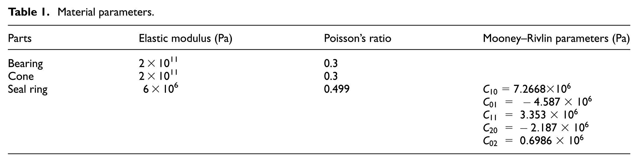
Stress distribution
The stress distribution of the sealing ring with conical teeth is more uniform than that of the sealing ring with spherical teeth. The lifetime of the sealing ring is extended by having a more uniform stress distribution. As shown in Figure 4(a), the maximum stress in the sealing ring with spherical teeth is mainly concentrated in the central zone. Because the stress is generated at the point of contact with the sealing surface, the stress gradually spreads from the sealing surface to the middle zone. When the maximum stress occurs at the center of the sealing ring, the sealing ring suffers extensive deformation and significant damage will be caused. As shown in Figure 4(b), the stress at the center of the sealing ring with conical teeth is smaller than that at the sealing surface, and the high stress is concentrated at the four corners, which are regarded as the main sealing surfaces. Compared with the sealing ring with spherical teeth, the stress distribution in the sealing ring with conical teeth is more uniform and the deformation is thus smaller.
Stress value
According to the design criteria, the maximum stress must be greater than or equal to the pressure of the medium to meet the sealing requirements, otherwise, it will lead to leakage. 27 Therefore, the maximum stresses of the sealing rings with the two different kinds of teeth are 3.32 and 7.1 MPa, which are both greater than the medium pressure of 1 MPa and thus, meet the sealing performance requirements. The stress at the middle of the sealing ring with spherical teeth (3.32 MPa) is greater than that at the center of the sealing ring with conical teeth (3.16 MPa). This indicates that the compression deformation of the sealing ring with conical teeth is smaller.

Von Mises stress distributions of the seal rings with (a) spherical teeth and (b) conical teeth.
Strain
Strain distribution
The strain and stress distributions of the sealing rings are similar. The strain distribution of the sealing ring with conical teeth is more uniform than that of the ring with spherical teeth. Figure 5(a) shows that the maximum strain of the sealing ring with spherical teeth also appears at the center of the sealing ring. At the point where the stress is the highest, the strain is also at its highest. These results also confirm the accuracy of the simulations. When a load displacement was applied, compression and deformation occurred preferentially at the contact surfaces of the sealing ring teeth and then transferred from the contact surfaces to the center of the ring. When the stress and strain at the center of the sealing ring are at a maximum, the compression deformation is high. Figure 5(b) shows that the maximum strain also appears at the corner of the sealing ring with conical teeth. Unlike the sealing ring with spherical teeth, the maximum stress in the ring with conical teeth is not centered, so the deformation of the sealing ring with conical teeth is smaller.
Strain value
The maximum strain (0.17) at the center of the sealing ring with spherical teeth is higher than that (0.15) of the ring with conical teeth. Therefore, the compression deformation of the sealing ring with conical teeth is lower.
Von Mises strain distributions of the seal rings with (a) spherical teeth and (b) conical teeth.
Contact pressure
Contact pressure distribution
The contact pressure distribution of the sealing ring with conical teeth is more uniform and reasonable than that of the ring with spherical teeth. Figure 6(a) shows that the maximum contact pressure for the spherical teeth occurs at the center of the seal surface, whereas the minimum pressure appears on both sides of the sealing surface. Low lateral pressure can ease the entry of mud particles into the spaces between the cone and the bearing, which then leads to wear. Figure 6(b) shows that the maximum contact pressure for the conical teeth appears on both sides of the sealing surface, which can thus prevent the entry of mud and achieve a reliable seal.
Contact pressure
The maximum contact pressures of the sealing rings with spherical and conical teeth are 3.54 and 9.13 MPa, respectively. These values are both higher than the load pressure (1 MPa) and can thus meet the seal requirements. The contact pressure (3.54 MPa) at the center of the sealing surface of the sealing ring with spherical teeth is higher than that (2.03 MPa) of the ring with conical teeth. This result shows that the compression deformation of the sealing ring with conical teeth is lower, and thus the sealing ring with conical teeth is selected.

Contact pressure distributions of the seal rings with (a) spherical teeth and (b) conical teeth.
Comparison with other seals
In recent years, double and single metal seals have been the most widely used seals, so we have compared the sealing performance of our newly proposed seal with the performances of these two sealing rings.
Material model
The rubber material used for the three seals is the same; therefore, a five-parameter M-R model was used to describe the constitutive model of the rubber materials, as mentioned in our previous study (see section “Constitutive model of the rubber material”). The roller, the bearing, and the metal rings are all rigid metal elements. Metals can be treated as linear elastic, ideal elastic–plastic, and isotropic materials. The metal characteristics can be defined using an elastic modulus (2 × 10¹¹ Pa) and Poisson’s ratio (0.3).
Finite element model
Figure 3(c) shows the finite element model of the double metal seal, its working principle, and the finite element model building process that was described in our previous studies. 26 Here, we compare the results for the double metal seal with those for the newly designed seal.
Figure 3(d) shows the finite element model of a single metal seal. The single metal seal is composed of moving and floating metal rings and an O-ring. The moving ring and the roller are connected. The sealing surface is located at the contact point between the floating and moving metal rings and is also called a dynamic sealing surface. When the bit rotates, the moving ring and the cone rotate together, and the floating ring is driven to rotate; however, the speed of the floating ring is much lower than that of the moving ring. A rubber O-ring is placed and compressed between the floating metal ring and the bearing. The O-ring provides an axial and radial seal that prevents mud particles from entering the seal, and also prevents lubricating grease leakage. The finite element model of the single metal seal is similar to that of the double metal seal with the addition of the contact pairs and the loading. Three contact pairs exist between (1) the rubber ring and the bearing, (2) the floating metal ring and the rubber ring, and (3) the floating and moving metal rings. The loading includes the following steps: (1) a full constraint is applied to the moving metal ring, (2) a radial constraint is applied to the floating metal ring, (3) the bearing moves axially downward and a radial constraint is applied to the bearing, and (4) the working pressure difference is applied at the top of the floating metal ring.
Results and discussion
From the above analysis, we know that the strain and stress distributions are the same, so we simply analyze the stress and the contact pressure, and the strain is not studied here.
Stress
(1) Compared with the other two seals, the stress distribution in the new seal is the most uniform. According to the results of previous studies, 26 Figure 7(a) shows that the stress distribution that occurs on the seal surface between two metal rings is uneven; the maximum stress (24 MPa) occurs on the inside of the sealing surface (near the bearing), while the minimum stress (0 MPa) occurs on the outside of the sealing surface (near the cone). The stress distribution of the two rubber rings is nonuniform; the maximum stress occurs at the center, which indicates that the rubber rings are overcompressed. 26 Higher stress yields a greater deformation and thus leads to a more serious failure. Figure 7(b) shows that the stress distribution of the single metal seal is the same as that of the double metal seal. While the seal forms are different, the stress distributions of the single and double metal seals are the same, and the stress trend has not changed fundamentally. From field-usage data, we know that the lifetime of a metal seal is short (in general, the lifetime ranges from more than 10 h to a few tens of hours), so the performance of the metal seal is not ideal. It is therefore important to study the new seal. Figure 7(c) shows that, compared with the two metal seals, the stress distribution of the new seal is more uniform. The maximum stresses in the new seal occur on the seal surfaces (i.e. on the surfaces between the ring and the cone and between the ring and the bearing), and the stress at the center is small, which indicates that the deformation is small. (2) Compared with the metal seals, the maximum stress in the new seal has the lowest value. The maximum stresses of the double metal seal, the single metal seal, and the new seal are 24, 14.6, and 7.2 MPa, respectively. Because the maximum stress in the new seal is the lowest, the stresses in the other areas of the seal also have the lowest values.
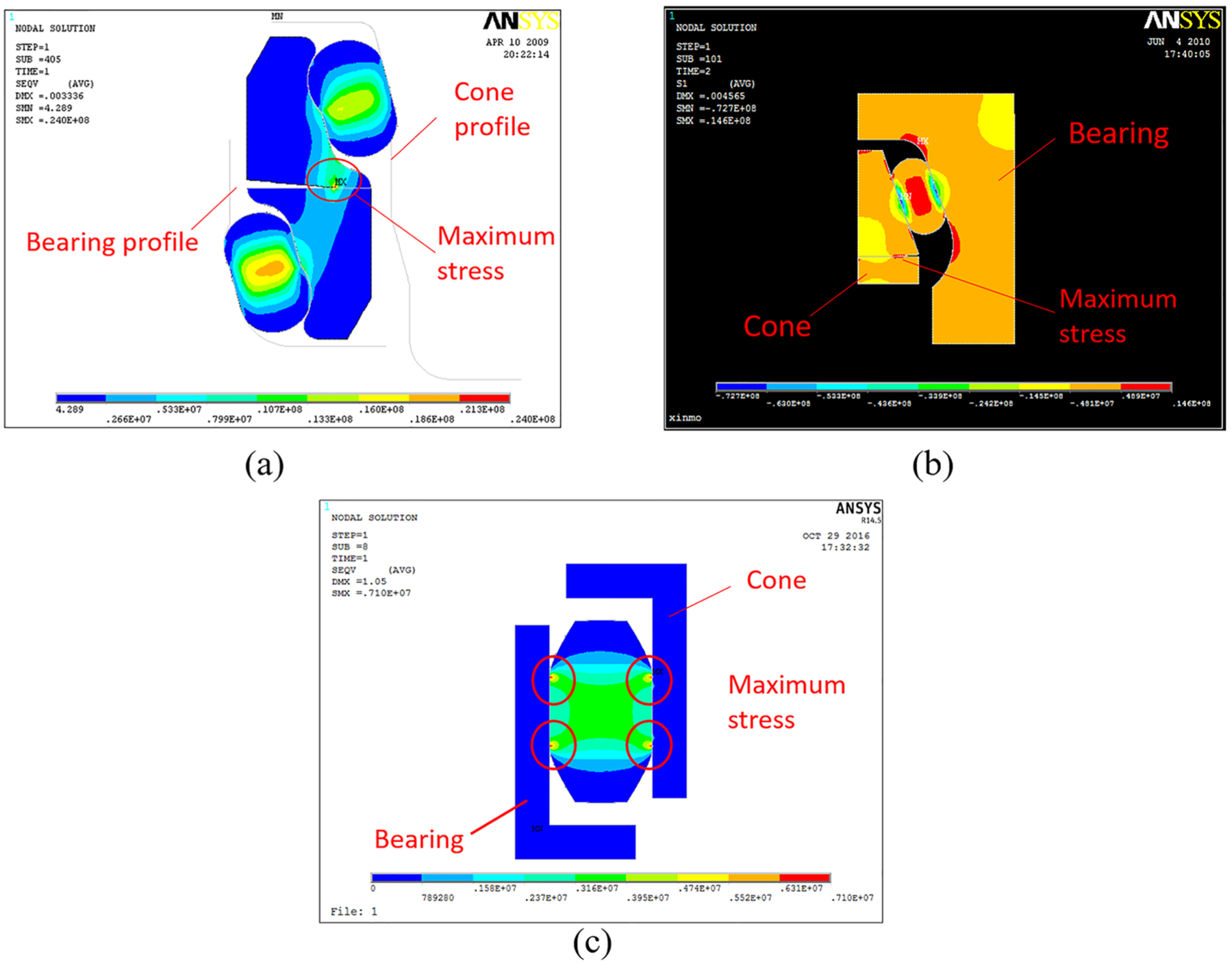
Stress comparison of the different seals: (a) double metal seal, (b) single metal seal, and (c) newly designed seal.
Contact pressure
(1) Compared with the other two seals, the contact pressure distribution of the new seal is both the most uniform and the most reasonable. Figure 8(a) shows that, according to the results of previous studies, the maximum pressure occurs on the inside of the metal seal surface (near the bearing), while the minimum pressure occurs on the exterior of the metal seal surface (near the cone), because any mud enters the sealing surface from the cone side, while grease enters the sealing surface from the bearing side. This pressure distribution allows mud particles to enter the seal surface more easily, but it also makes it difficult for the grease to enter the sealing surface to provide good lubrication. 26 Figure 8(b) shows that the pressure distribution on the rubber ring of the single metal seal is the same as that on the corresponding ring of the double metal seal. This pressure distribution is still unable to prevent mud from entering the seal surface. The pressure trends of the two metal seals have thus not been changed fundamentally. Figure 8(c) shows that the maximum pressure occurs in the corner, while the pressure values in other areas are essentially identical, and this pressure distribution is thus the most uniform. The pressure distribution is reasonable, which means that the maximum pressure on the outside of the seal surface can prevent mud from entering the seal surface. (2) Compared with the other two seals, the maximum contact pressure of the new seal is the lowest. The maximum contact pressures of the double metal seal, the single metal seal, and the new seal are 24.8, 13, and 9.13 MPa, respectively, which are greater than the downhole pressure (0.3–0.7 MPa). Lower contact pressure leads to reduced wear.

Contact pressure comparison of the different seals: (a) double metal seal, (b) single metal seal, and (c) newly designed seal.
To date, there has only been limited work on bionic nonsmooth surface seals, which means that the newly proposed and innovative structural design is likely to have good application prospects.
Conclusion
A bionic nonsmooth surface seal has been designed. Spherical and conical teeth are present within the inner and outer diameters of the sealing ring. Their structural parameters have been determined, including the inner and outer diameters, cross-sectional widths, height, number of teeth required, radius of the spherical teeth, cone angle, and fillet radius of the conical teeth.
The sealing performances of the sealing rings with the spherical and conical teeth have been analyzed and compared via FEA. Uneven and irrational distributions and high values of stress, strain, and contact pressure occur in the sealing ring with spherical teeth and, thus, the sealing ring with conical teeth was selected as the new seal.
Compared with other metal-type seals, the stress and contact pressure distributions in the new seal are the most uniform and reasonable. The stress and contact pressure values are also the lowest, and this leads to a desirable sealing performance.
Footnotes
Handling Editor: ZW Zhong
Declaration of conflicting interests
The author(s) declared no potential conflicts of interest with respect to the research, authorship, and/or publication of this article.
Funding
The author(s) disclosed receipt of the following financial support for the research, authorship, and/or publication of this article: This work was supported financially by the Education Key Laboratory of Southwest Petroleum University (OGE201403-07).