
Abstract
In this article, the most important part of the automotive front bumper system, namely, the bumper beam, is studied by changing the material and thickness to improve the crashworthiness performance in low-velocity impact. According to the low-speed standard of automotives stated in E.C.E. United Nations Agreement, Regulation no. 42, the low-velocity impact simulation based on finite element analysis is carried out. Lightweight is the main purpose of this article. First, the bumper beam analysis is accomplished for carbon fiber composite and steel material to analyze their deformation, weight, impact force, energy absorption, and the acceleration of the impactor. As a consequence, the bumper beam made by carbon fiber composite achieves better impact behavior. Second, on the purpose of lightweight, the bumper beams of different thickness including 5.4, 6, 6.6, and 7.2 mm are investigated. The results show that the 5.4 mm bumper beam is the best selection without sacrificing the impact performance. Third, according to the stress distribution, the thickness distribution of the bumper beam is changed to get better lightweight results. It is indicated that the weight of the improved bumper beam is further reduced and the impact performance is not weakened.
Introduction
When accidents of frontal impact occur, the front bumper system, which may to some extent protect the car body and passengers, is the first part that receives the collision. 1 This system is made up of three main parts: fascia, energy absorber and bumper beam. 2 The fascia is a non-structural component that reduces the air resistance, while the energy absorber dissipates part of the kinetic energy during collision and the bumper beam is a structural component which absorbs the low impact energy by bending resistance. Generally speaking, the bumper system mainly has four functions. At first, it can protect the fender, radiator, engine hood, and lamps when low-speed impact happens between the automobile and the other automobiles or barriers and transfer the impact energy to other components of the automobile when high-speed impact occurs. Second, it should minimize the injury of the pedestrians while the car hits pedestrians. Third, it may fulfill the car body aerodynamic requirements. Finally, it can decorate and beautify the car body. Of the four functions, the first two, the focus of numerous studies, are particularly significant.
In the fact that the bumper beam is the key segment of the bumper system, there are lots of investigations concentrating on the bumper beam. Park et al. 3 developed a kind of bumper beam cross section which could satisfy the safety requirements not only for a front rigid-wall impact but also lower leg injuries in a pedestrian impact test. Farkas et al. 4 studied the optimization of a vehicle bumper subsystem with fuzzy parameters. This article presented the application of the fuzzy finite element analysis (FEA) in conjunction with Possibility-Based Design optimization in the context of crashworthiness. Early bumper beam is made by steel. But considering the factors such as lightweight design, fuel consumption, and environmental legislations, the demand of manufacturers cannot be better satisfied using this kind of material. Under this circumstance, a lot of new materials are applied to the manufacturing of the bumper beam. Marzbanrad et al. 5 analyzed the automotive bumper beam in low-speed frontal crashes. He used the material such as steel, aluminum, magnesium, Glassfiber Mat Thermo-plastic (GMT), and Sheet Molding Compound (SMC). And through comparing the weight and impact behavior, he found that high-strength SMC composite was proposed to replace GMT as it could minimize the bumper beam deflection, impact force and stress distribution; and maximize the elastic strain energy. Davoodi et al. 6 studied the mechanical properties of hybrid kenaf/glass-reinforced epoxy composite for passenger car bumper beam. The results indicated that some mechanical properties such as tensile strength, Young’s modulus, flexural strength, and flexural modulus were similar to GMT, but the impact strength was lower. So the hybrid kenaf/glass-reinforced epoxy composite had the potential application value in some car structural components such as bumper beams. Belingardi et al. 7 studied the geometrical optimization of bumper beam profile made of pultruded composite. In this article, E-Glass/epoxy pultruded bumper beam was considered and its energy absorption capability was compared with steel and E-Glass/epoxy fabric composite. Results indicated that the pultruded bumper beam had comparable energy absorption capability with respect to the steel normal production solution. The new composite solution, which had appropriate optimization of bumper beam section profile and beam curvature, had better energy absorption characteristics.
A great many of investigations have been carried out for thin-walled structures under impact loading.8–12 The bumper beam in this article is made of thin-walled structure too. The method of FEA is adopted in this article.
In this article, how the material can influence the impact behavior is investigated. This is accomplished by using two approaches. First, change the material of the bumper beam from steel to carbon fiber composite. Through respectively simulating, it turns out that when it comes to lightweight, the carbon fiber composite material has a big advantage over steel. And second, vary the thickness of the bumper beam made by carbon fiber composite on the purpose of achieving the best lightweight results.
The low-velocity impact simulation conditions in this study follow the ECE R042 standard, which requires that the function of automobiles does not suffer damage after impact. The reference for ECE standard which is related to the low-velocity impact will be introduced in detail in the section “Finite element model” when establishing the finite element model.
Impact theory
There are two different kinds of impacts, that is, elastic impact and plastic impact. In an elastic impact, a little of energy that can be neglected is lost between the two impacting objects, while in a plastic impact, there is a great deal of energy dissipated in the collision. The type of impact which occurs between the front bumper system and an impactor in this article is elasto-plastic impact because the severe crash force exists. Since transient and nonlinear analyses are involved, the impact phenomenon is very complex. Of particular interest here is to study the impact behavior of the contact area.
The total energy is conserved throughout the impact process. Moreover, since in the process of collision, the objects contact with each other for a short time and the interaction force which makes the internal force far outweigh the external force is too big, the momentum before an impact is equal to the momentum after the impact. The energy and momentum conservation equations after separation point can be expressed as follows 5


where mA is the mass of the impactor, mB the mass of vehicle, vA the velocity of the impactor before impact, vA 1 the final velocity of the impactor after separation point, and vB 1 the final velocity of vehicle after separation point.
Another deterministic criterion to measure the impact is the coefficient of restitution abbreviated simplified as COR, which is the ratio of the speed differences after and before a collision 5

On a collision course, the mass of the contactors is constant but their velocity suffers great changes. Therefore, the COR is a useful factor to measure the energy variation. The COR value of 1.0 stands for elastic collision, while perfectly plastic impact occurs when the value is zero. This number can infer how much kinetic energy remains after impact. The higher the number is, the more the kinetic energy is left. On the contrary, when the value is closed to zero, there is much kinetic energy converted into the internal energy. Since the type of this article is elasto-plastic impact, the COR value is located between the interval [0, 1]. That is to say, in the process of collision, part of the kinetic energy is absorbed. The plastic strain energy which is represented by the letter E is gained by subtracting the kinetic energy of the vehicle and the impactor after impact from the kinetic energy of the impactor before impact

Finite element model
Clearly, for FEA, there are several factors that will influence the quality or accuracy of the results obtained. 13 Meaningful or useful results will depend on the type of elements employed, the element quality, the number of elements used, and the simulation of boundary constraints and loading conditions. 13 Since the software Altair HyperMesh has great advantages over other software in meshing, it is adopted in this study.
At first, the computer-assisted design (CAD) data of the impact model was imported to the coupling environment of Altair HyperMesh and LSDYNA. Second, the geometry cleanup and meshing were done to the model. The finite element model after meshing is shown in Figure 1. Figure 1(a) is the impact finite element model and Figure 1(b) is the finite element model of the bumper system.
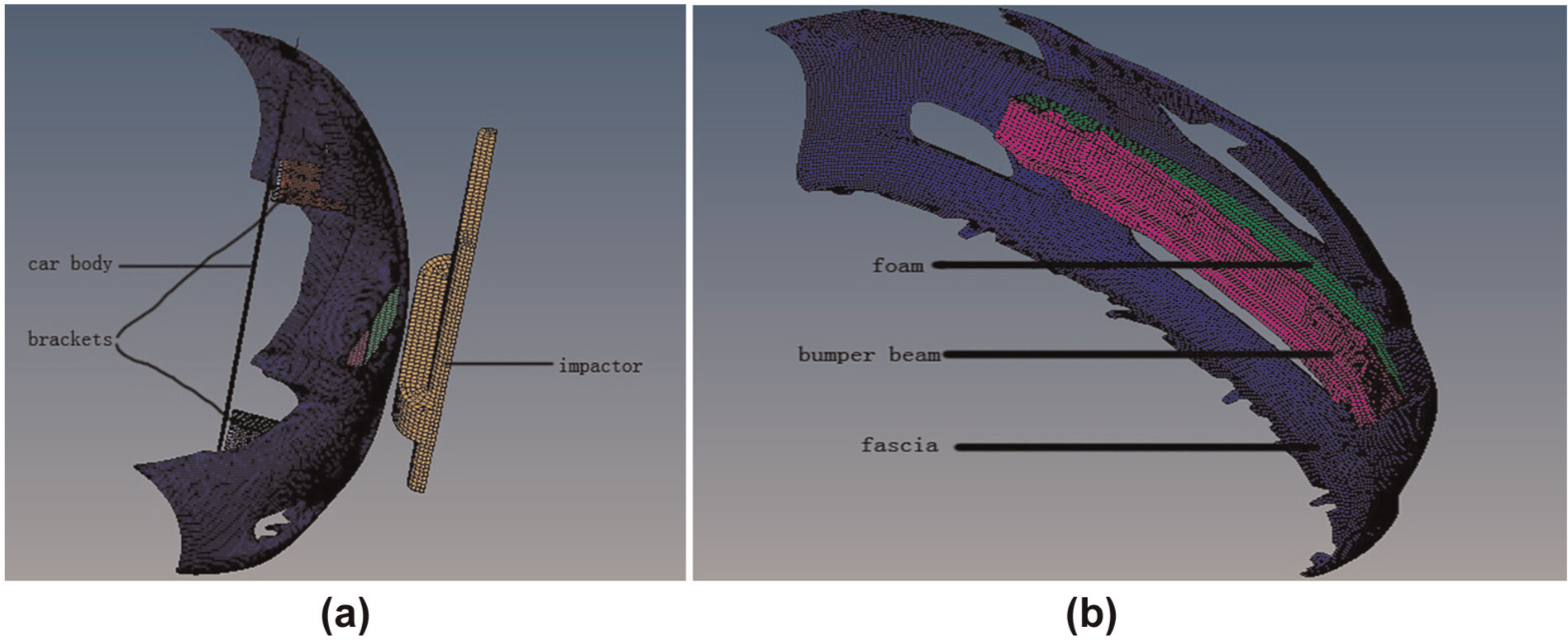
Finite element model after meshing (a) is made up of four sections, namely the car body, the brackets, the bumper system and the impactor and (b) consists of three parts, namely the bumper beam, the foam and the fascia.
The bumper beam is attached to two energy absorbing brackets as shown in Figure 1(a), and the brackets are attached to the thin-walled structure which is used to simulate the car body using the rigid steel material. The connector between the car body and the energy absorbing brackets is accomplished by shifting the rear circle grid of the two brackets to the car body. The connector which is also used for the brackets themselves between the brackets and the bumper beam is achieved by setting up rigid joints.
Nonlinear explicit impact modeling elements were used in this study. Because the thickness of the bumper beam, brackets, fascia, and car body is much smaller than the other dimensions, the shell element is the best choice for meshing. While the energy absorption foam as well as the impactor is a three-dimensional solid, the best type of element is the solid element.
The shell elements of the bumper beam, brackets, and fascia are mainly quadrilateral elements with fewer triangular ones because of geometry limits. The car body is meshed by quadrilateral elements. The impactor and foam are modeled with hexahedral elements which have higher accuracy and produce fewer nodes.
Material type MATL 57 (mat-low-density-foam) is used for simulation of the foam. Material type MATL 24 (mat-piecewise-linear-plasticity) is used for simulation of the bumper beam, fascia, and brackets. Material type MATL 55 (mat-enhanced-composite-damage) is used for simulation of the carbon fiber composite. Material type MATL 20 (mat-rigid) is used for simulation of the impactor and the car body.
The type of automatic-surface-surface contact is considered to simulate the interfaces of this impact model. The automatic-single-surface contact is defined to the set containing the fascia, bumper beam, and brackets. All friction is ignored. The finite element model characteristics of each component in the original modeling are shown in Table 1.
Finite element model characteristics of the models.
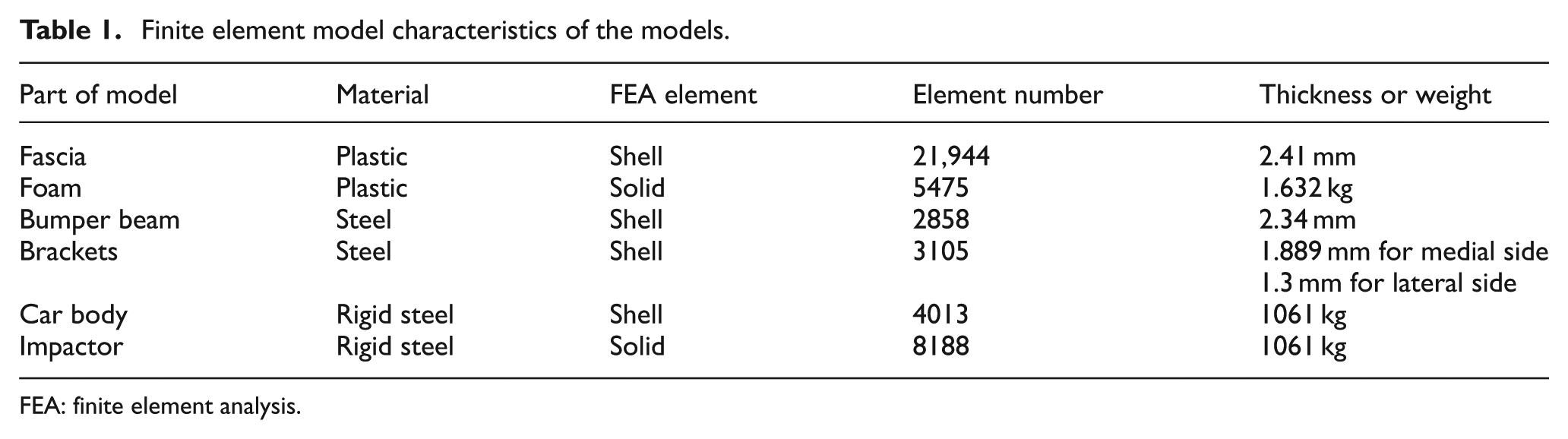
FEA: finite element analysis.
According to the ECE standard, the impactor collides to the bumper system in straight direction. The velocity of the impactor is 4 km/h, and the height of the impactor baseline is 445 mm away from the ground at the same time the baseline keeps horizontal. The ECE R042 standard also requires that the automotive brakes should be released and the transmission is in the neutral position. This request is equal to fix the bumper system to a movable platform. Gu et al. 14 came up with a simplified method by making the impactor collide to the bumper which is fixed to the fixed rigid metal frame. They used the equivalent energy method to analyze the initial impactor velocity relationship of the two different ways and proved the validity of the method. According to that method, the equivalent initial velocity of the impactor is gained through equation (5)
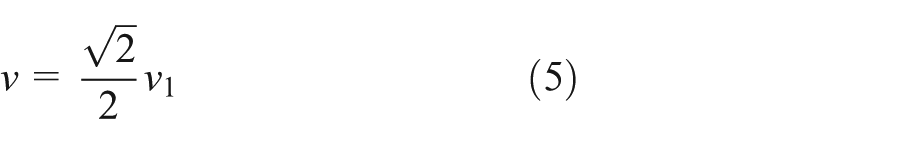
where v 1 is the initial velocity of the impactor provided in the ECE R042 standard and v the initial velocity of the impactor used in this article.
For impact simulations, the finite element model was revealed by LSDYNA solver. And HyperView and HyperGraph were used for post-processing.
Bumper beam material
The choice of the bumper beam material has a vital effect on the impact performance of the vehicle. A proper selection can minimize the weight and get high fuel efficiency without sacrificing the strength.
It is said that 75% of fuel consumption directly relates to vehicle weight. Lightweight composite materials provide opportunities for reducing vehicle weight, thus increasing fuel efficiency and reducing emission of harmful pollutants. On the condition of everything else remaining the same, 6%−8% increase in fuel economy can be realized for every 10% reduction in weight. The advantages of composites compared to steels for automobiles are 15 (1) weight reduction of 20%−40%; (2) styling flexibility in terms of deep drawn panels, which is a limitation in metal stampings; (3) 40%−60% reduced tooling cost; (4) reduction in assembly cost and time; (5) resistance to corrosion and scratches, reduced noise vibration harshness (NVH), and higher damping; (6) materials and process innovations capable of adding value while providing cost savings; and (7) safer structures due to higher specific energy absorption.
Carbon fiber composites are called as the 21st century automotive materials. It has many advantages such as low density, high strength, high modulus, high temperature resistance, corrosion resistance, self-lubricating, good conductivity/thermal performance, and low thermal expansion coefficient. Because of so many excellent properties, the carbon fiber composites become very important raw materials in preparing various structural and functional composites.
Fiber-reinforced polymer composites possess several advantages over steel, the most salient of which are their high strength-to-weight ratio and excellent corrosion resistance. 16 Carbon fiber composites can not only increase the strength of the structure but also decrease the weight of the structure. There are some articles studying the application of carbon fiber composites in the automobiles. Bambach 17 investigated the application of carbon fiber strengthened steel tubes to the frontal crush tubes of two different passenger vehicles under frontal collisions. Substantial improvement, namely, the potential for vehicle light-weighting, was accomplished. Such components had the potential to contribute to improvements in fuel efficiency and emissions reductions in future passenger vehicles. Bambach 18 also studied the structure of carbon fiber composite strengthening of thin steel passenger vehicle roof. Such fiber strengthening structure could gain substantial increases in force resistance for steel tubes under both axial crushing and pure bending. And the implications with regard to vehicle light-weighting were discussed. It was shown that fiber composite strengthening of vehicle structure had the potential to contribute to higher roof strength and light-weighting. Bussadori et al. 19 studied carbon fiber–reinforced plastic (CFRP) crushing structures in explicit crash. They used two different numerical models to analyze several different parameters on the final results. The work showed the advantages of crushing zone modeling compared to a stacked shell one.
However, relative to the materials such as steel or aluminum, the price of the carbon fiber composites is too expensive to be widely used in the automobile manufacturing. Since a lot of research institutions are sparing no efforts to reduce the manufacturing cost of carbon fiber composites, the commercialization of carbon fiber composites automobiles will come true in the near future. Therefore, carbon fiber composites are used to the bumper beam instead of steel in this investigation.
In order to study the effect of the type of material on the impact behavior, the specifications of steel and carbon fiber composite were assigned to the bumper beam in separate impact simulations. Other characteristics of the model such as fascia, foam, brackets, impactor, and so on remained constant. Mechanical specifications of the original model are illustrated in Table 2. In Table 2, ρ stands for the density and Sy the yield stress, E the Young’s modulus, υ the Poisson’s ratio.
Material properties of the original model.
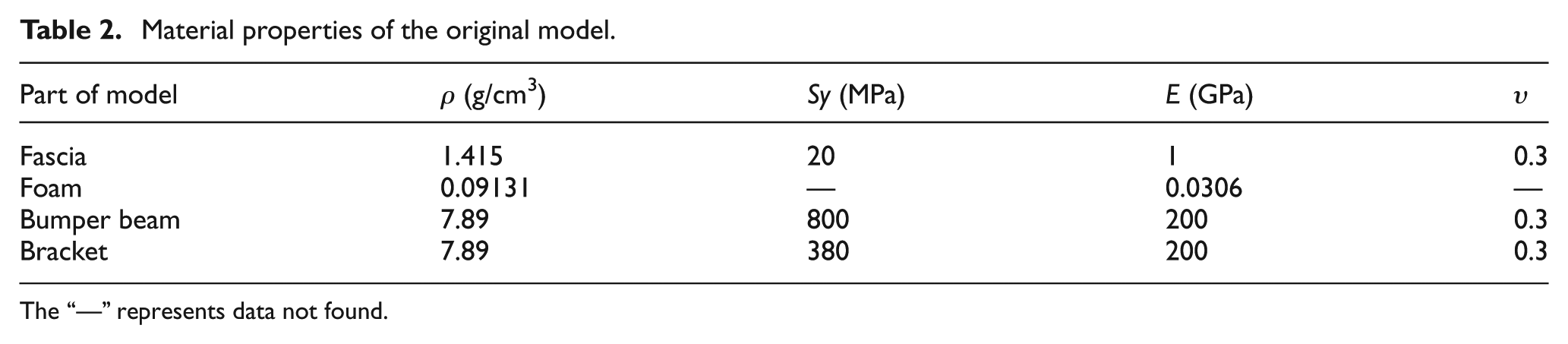
The “—” represents data not found.
The type of the carbon fiber composite used in this article is T300/5208 whose density is 1.6 g/cm3 and carbon content is 70%. The Poisson’s ratio (υ 12) of the carbon fiber composite is 0.285. Table 3 shows its other mechanical parameters. The thickness of the bumper beam is 6.6 mm. The fiber orientation is [0, 90, 0, 45, −45]11.
Mechanical parameters of T300/5208.
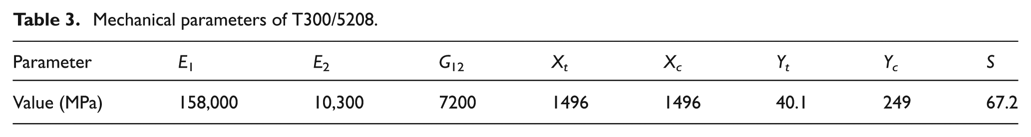
In Table 3, E 1 stands for the longitudinal tensile elastic modulus and E 2 the transverse tensile elastic modulus, G 12 the shear modulus, Xt the longitudinal tensile strength, Xc the longitudinal compression strength, Yt the transverse tensile strength, Yc the transverse compressive strength, and S the shear strength.
Figures 2 and 3 show the energy curves of the two impact models whose bumper beam is made by steel and carbon fiber composite, respectively. Through analyzing the energy curves, the validity of the finite element model can be determined. In this article, in order to speed up the computing speed, the reduced integration is used. But this method can cause a zero-energy model which is called hourglass. If the hourglass energy is less than 5% of the total energy, the finite element model is reliable. Because the hourglass energy is too small to show, the hourglass energy curve is shown in another picture.

Energy curve of the model with the bumper beam made by steel.

Energy curve of the model with the bumper beam made by carbon fiber composite.
According to Figures 2 and 3, in the process of collision, the kinetic energy decreases while the internal energy increases. This change indicates that the kinetic energy is absorbed by the bumper system. Then the kinetic energy increases while the internal energy decreases. The change indicates that the springback occurs in the bumper system. Obviously, in the two figures, the total energy is constant. In Figure 2, the maximum hourglass energy is 0.88 J, which is 0.27% of the total energy. And in Figure 3, the maximum hourglass energy is 1.42 J, which is 0.43% of the total energy. Therefore, the hourglass energy of the two impact models has no significant effect on operational results. So the finite element model is authentic.
The ECE R42 standard does not provide a reference point to measure the deformation. The center of the impact point is unrepresentative sometimes. So the node 2031050 whose deformation is the biggest in the bumper beam is taken as a reference point to observe the deformation of the bumper beam. The deformation versus time diagram is shown in Figure 4. The maximum deformation is 19.1 and 16.3 mm, and the maximum deformation point is 0.084 and 0.080 s for steel and carbon fiber composite, respectively. The reason for this situation is that the stiffness of carbon fiber composite is higher than the stiffness of steel. According to experience, when the deformation changes to the lowest value with a slight fluctuation, the collision ends. So as shown in Figure 4, the end time of collision is 0.1373 and 0.1356 s for steel and carbon fiber composite, respectively. Since the plastic deformation occurs in the bumper system, the last deformations of the two bumper beams do not become zero.

Steel and carbon fiber composite bumper beam deformations.
By analyzing the change of energy which is obtained by the output of the software HyperGraph from Figures 2 and 3 and the deformations from Figure 4, the bumper system whose bumper beam is made by carbon fiber composite absorbs nearly the same kinetic energy. But the maximum deformation of the carbon fiber composite bumper beam is lower than that of the steel bumper beam. So through using the carbon fiber composite, the impact performance of the bumper beam is improved.
The impact force between the impactor and fascia which is shown in Figure 5 is also a significant parameter to be studied in this article. According to Figure 5, the maximum impact force is 25.5 and 25.0 kN for steel and carbon fiber composite, respectively.

Impact force between impactor and fascia of two bumper systems.
Another parameter to be investigated is the acceleration of the impactor. The acceleration versus time curve is shown in Figure 6. As shown in this figure, the maximum acceleration of impactor is 24055.9 and 23553.6 mm/s2 for steel and carbon fiber composite, respectively.
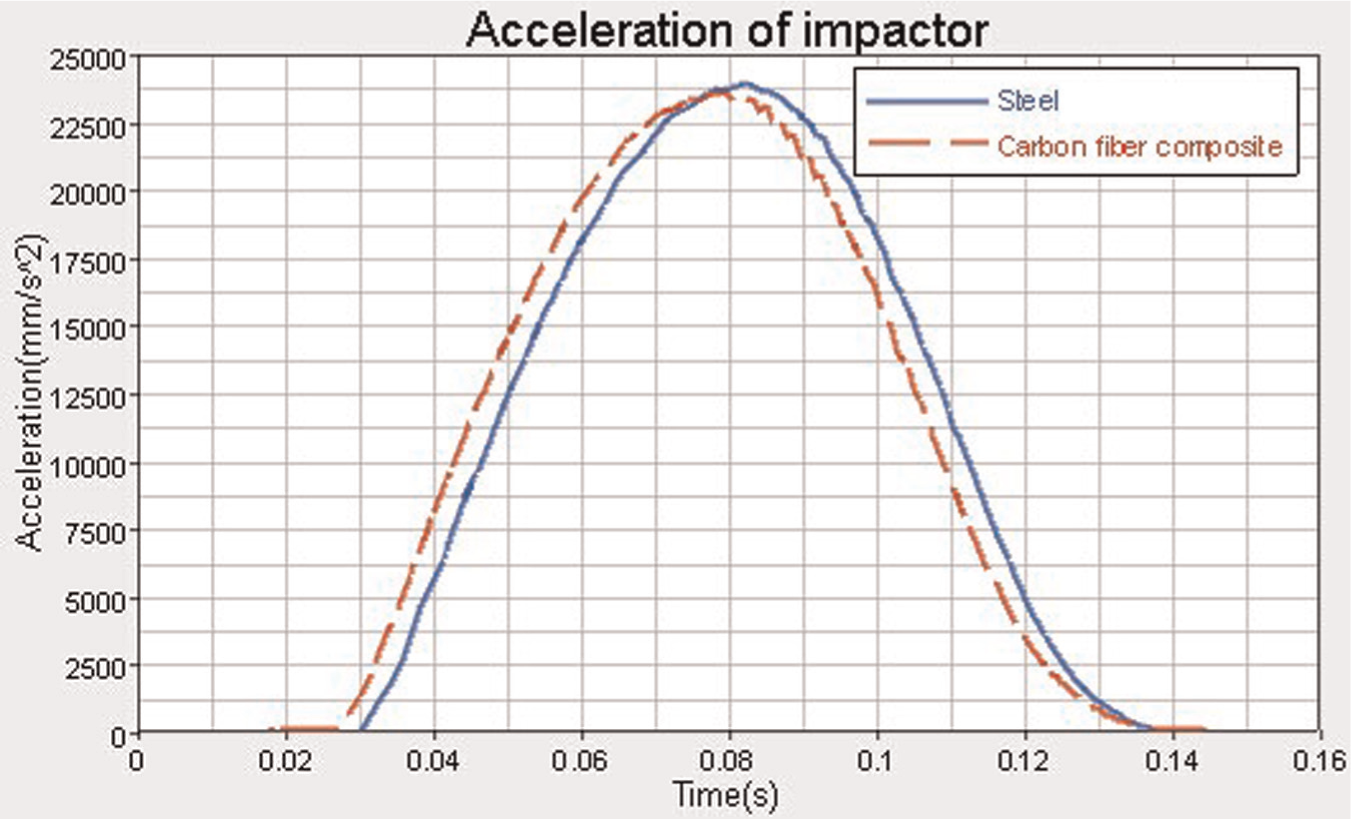
Acceleration of impactor of two impact models.
After comprehensive analysis of Figures 5 and 6, it is clear that both the impact force between the impactor and fascia and the acceleration of impactor are decreased slightly using carbon fiber composite instead of steel. So the work that remains to be done is to study the parameters of the carbon fiber composite in order to improve the impact performance of the bumper system.
Bumper beam thickness
On the basis of reading a large number of references, a conclusion is drawn that materials with different thicknesses can gain different performance. So in this article, different thicknesses of carbon fiber composite bumper beam are taken into consideration to achieve the effect of thickness on impact performance of the bumper system. The thickness of the bumper beam is 5.4, 6.0, 6.6, and 7.2 mm as shown in Figure 7. As we can see in this figure, the maximum deformation of the beam decreases and the rate of decrease becomes less with the increase of thickness.

Effect of thickness on the deformation of bumper beam.
However, the value of the acceleration of impactor which is shown in Figure 8 increases with the increase of thickness. The increase of impactor acceleration can lead to the increase of impact force between impactor and fascia as shown in Figures 7 and 8. Therefore, it does not mean that the thicker the better.
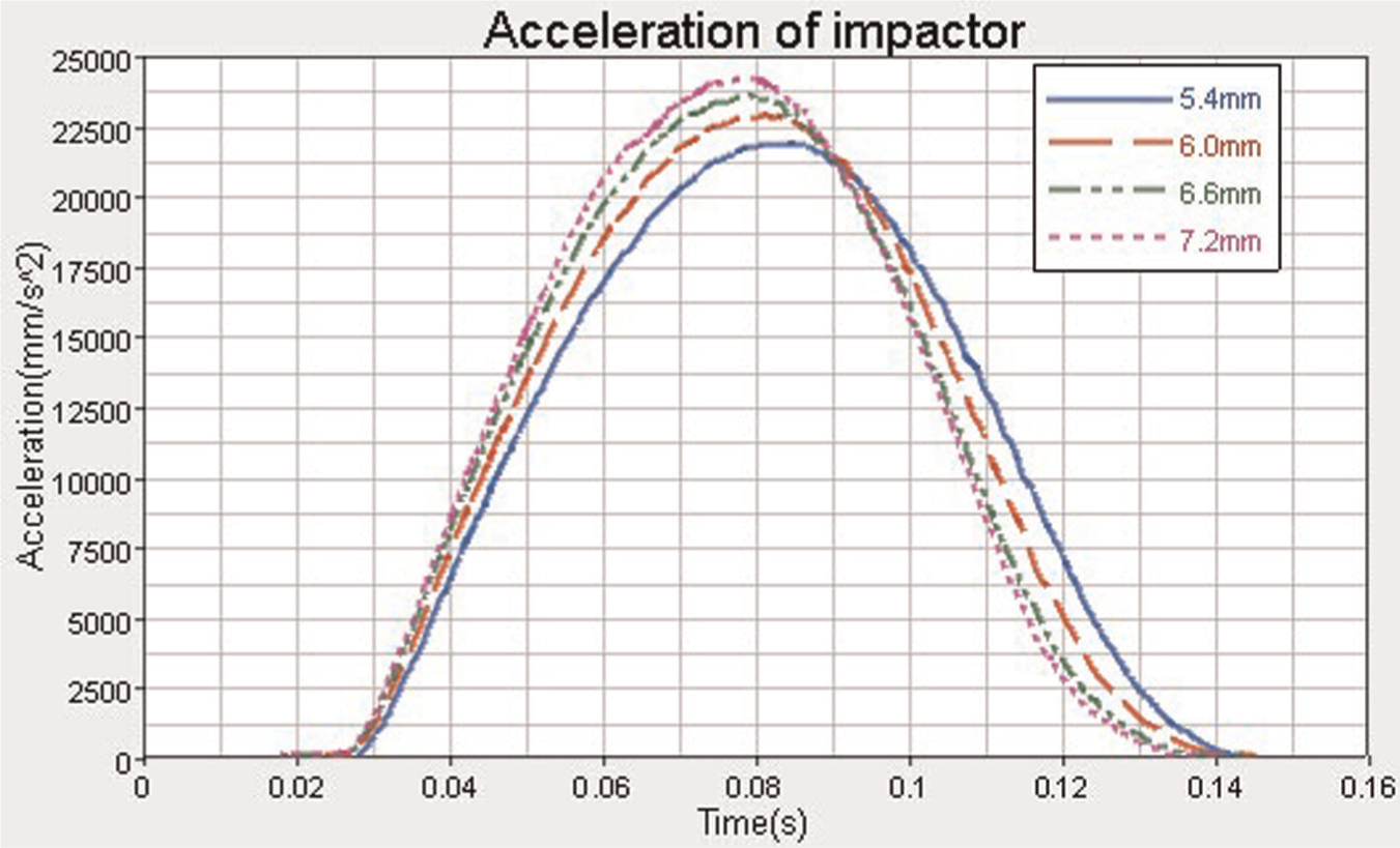
Effect of thickness on the acceleration of impactor.
The main purpose of this article is lightweight without sacrificing the impact behavior. From the viewpoint of impact performance, reducing the maximum acceleration can improve the level of protection of other body parts and passengers. Therefore, the bumper beam with less thickness is better. Through comparing with the bumper system with steel bumper beam, the maximum deformation of the bumper system with a 5.4 mm bumper beam is 18.8 mm, which is less than 19.1 mm, and the maximum acceleration of impactor is 22052.7 mm/s2, which is less than 24055.9 mm/s2, so the 5.4 mm bumper beam is regarded as the best choice. The weight of the original steel bumper beam is 4.96 kg, while the weight of carbon fiber composite bumper beam is just 2.32 kg. The weight reduction ratio of carbon fiber composite bumper beam is up to 53.2%.
Improvement of the bumper beam structure
The von Mises stress distributions of carbon fiber composite bumper beam and steel bumper beam are shown in Figure 9. According to Figure 9, at 0.072 s, the von Mises stress has the biggest value. The von Mises stress of steel bumper beam is 1073 MPa, while the von Mises stress of carbon fiber composite bumper beam is 1466 MPa. Even though the stress value of carbon fiber composite bumper beam is bigger than that of the steel bumper beam, the stress distribution of the former is better than the latter.

Von Mises stress distribution of carbon fiber composite and steel bumper beam.
The problem remaining to be solved is to further reduce the weight of the carbon fiber composite bumper beam through changing its structure considering satisfying the impact performance. Reducing the thickness of some places can further reduce the weight. Whether the changed structure satisfies the impact performance remains to be proved through comparing the parameters before and after improvement in the following content. Figure 10 shows the improved bumper beam. Its thickness of left and right sides is 4.2 mm, and its middle part is 5.4 mm.
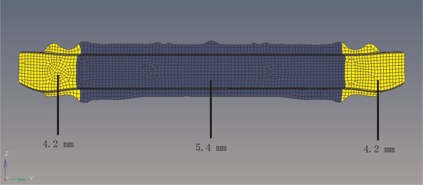
Improved bumper beam.
The impact results of bumper beams before and after improvement are shown in Table 4. According to Table 4, in addition to the deformation, the other parameters of the improved bumper beam are better than that of the bumper beam with constant 5.4 mm. Of particular interest here are the reduction of maximum von Mises stress from 1466 to 1362 MPa and the decrease of the weight from 2.32 to 2.18 kg.
Impact results of bumper beams before and after improvement.

The impact results of the improved bumper beam and the steel bumper beam are shown in Table 5. According to Table 5, although the deformation and the maximum von Mises stress of the improved bumper beam are bigger than that of the steel bumper beam, the acceleration of impactor and the impact force between fascia and impactor have been reduced. And the reduction is necessary. Of great importance here is the decrease of the bumper beam from 4.96 to 2.18 kg.
Impact results of the improved bumper beam and the steel bumper beam.

Conclusion
When designing the bumper system, the deformation of the bumper beam must be less than a value in order to protect the other components from damage. And the maximum stress cannot exceed the yield stress. What is more, under the premise of satisfying the impact performance, the weight of the bumper beam should be minimized as much as possible.
Under the condition of low velocity impact, most of the energy is absorbed by the bumper system. After impact simulations in accordance with the ECE R042 standard considering the parameters which have influence on the impact performance, the following results are indicated:
Through the analysis of lightweight materials, the carbon fiber composite is selected as the material of the bumper beam instead of steel in order to achieve the lightweight design. Comparing with using the steel bumper beam, less bumper beam deformation, impact force between impactor and fascia, and acceleration of impactor can be gained by the carbon fiber composite bumper beam.
Through analyzing the impact behavior of different thickness bumper beams, the best choice of thickness is 5.4 mm. Its weight is 2.32 kg. Its weight reduction ratio is up to 53.2% than the steel bumper beam without sacrificing the impact performance.
Through changing the thickness distribution of the bumper beam as shown in Figure 10, the weight of the bumper beam is decreased further; at the same time, the overall impact performance is a little better than the unimproved one.
The steel can be replaced by the carbon fiber composite since the carbon fiber composite has great advantages over steel in terms of lightweight. These advantages are also conductive to the improvement of fuel efficiency and the decrease of emission of harmful pollutants.
Footnotes
Academic Editor: Xi Shi
Declaration of conflicting interests
The authors declare that there is no conflict of interests regarding the publication of this article.
Funding
This work is supported by Natural science fund project of Liaoning Province under Grant #20102189, Science and technology plan projects of Liaoning Province under Grant #2011220055, and fund project of Shenyang Tongchuang FRP Company under Grant #2012040503.