
Abstract
This article proposes a cooperatively analytic solving method that calculates the chute posture in the bending section. The method maintains a good posture of the scraper conveyor during its bending process and solves the feeding trajectory of the shearer accurately and precisely. This method modifies and perfects the existing method to obtain the main parameters of the bending section, including the postures of the chutes and pin rails, and the corresponding extension lengths of the advancing units. A virtual-reality software that can visually simulate this entire operation process under different conditions is developed. Considering the gap between the driving wheel and the pin rails, the relationship between the shearer yaw angle and shearer working trajectory in the feeding stage is investigated for different body lengths. The angular relationship between the left and right driving wheels and the pin rails is also researched. Finally, the proposal is verified in experiments on a test prototype and on physical equipment. This analytic method provides a theoretical basis for the cooperative three-dimension localization of three machines in a fully mechanized coal-mining face, ensuring safe automatic production of the mining face.
Keywords
Introduction
As a key equipment of a fully mechanized coal-mining face, the scraper conveyor mainly completes tasks such as transporting and shipping out cutting coal, running orbit of shearer, overall forward with the all working face, and coupling with the floor in real time. The bending length and angle of the bending section of a scraper conveyor is decided by the extension lengths of the advancing units of the corresponding hydraulic supports of every chute in the bending section. The chutes’ postures in the bending section directly affect the cutting trajectory of the shearer and determine the running stability and reliability of the shearer.
Previous research on scraper conveyors has mainly focused on dynamical problems, the meshing problem, and the wearing problem between the chain wheel and the chain under the no-bending condition.1–9 Studies that account for the bending section presume a certain shape of the bending section,10–18 and the actual chute posture of the bending section has been rarely investigated. 19 The fixed-shape assumption not only aggravates the differences between the theory and the actual conditions when solving the dynamics and other problems, but also introduces errors in the control of the associated shearer and the advancing units of the hydraulic supports.
Therefore, a method that accurately calculates the bending section of the scraper conveyor is urgently required. To this end, Zhang et al. 20 proposed a method that detects the layout of the scraper conveyor from the running trajectory and precise positioning of the shearer. Although their method is theoretically sound, the shearer model is driven by four small wheels, and the scraper conveyor model is too simple to capture the connection between the actual shearer and scraper conveyor. In addition, the practical application of the shearer positioning device is likely to be offset from the theoretical position. When operated underground, the device will also be subjected to various complex electromagnetic interferences and other factors.
To capture the overall relationship among the scraper conveyor, shearer, and hydraulic support, this article proposes a method that accurately calculates the main parameters of the bending section.
The chutes include all the middle troughs, change-line troughs, transition troughs, and raising troughs. As the size variation is small, all chutes are regarded as same sized.
Solving method and process
The solution process of the cooperative solving method to chutes in bending section is shown in Figure 1, which is divided into the following steps:
According to the performance of the scraper conveyor, preliminarily select the values of the bending angle α and the number of single half bending lengths N. Then accurately determine na.
Determine the accurate bending angle αa using na.
Solve the structure and posture of the chutes in the bending section.
According to the characteristic size, determine the equation of the pin rails. At the same time, determine the yaw angle and the running trajectory of the shearer using the shearer walking model.
According to the characteristic size, determine the coordinates of the push and pull holes of the chute and develop a quantitative model for pushing the conveyor of the hydraulic support.
By integrating all the algorithms of step (5) and step (6), a virtual-reality (VR) simulation software could conduct various simulations under different conditions.
The theoretical analysis model was verified by the physical experiment and the prototype experiments, respectively.

Overall research steps.
Calculation model of the bending section
Analysis of forming the bending section
Each chute of the scraper conveyor is connected to another chute by a dumbbell pin or a lantern ring, and every chute is connected to its corresponding hydraulic support with an advancing unit. By varying the extension lengths of the advancing units in the hydraulic supports, all chute joints maintain a symmetrical bending section. During oblique feeding, the shearer runs across the same bending section to move the distance of the cutting depth.
Existing solutions and problems
A detailed calculation method of the bending section was proposed in Wand, 21 and a more realistic calculation was proposed as follows 19

where B is the moving step distance of the scraper conveyor, which equals the cutting depth; A and l are the chute width and length, respectively; and b is the corresponding chord length of the included angle of the adjacent chute. As α is very small, the chord length and arc length can be regarded as equal.
This formula ignores the length of C3, the horizontal distance between the center of symmetry and the midpoint of the longitudinal line drawn from the chute contact point (see Figure 2). As this length is non-negligible in the actual bending process, equation (1) must be corrected.
Geometric configuration of chutes in the bending section.
Modified calculation model of the bending section
Let θn be the inclination angle between the nth chute in the bending section and the longitudinal line of the scraper conveyor. According to symmetry and stress analysis, if the total number of chutes in the bending section is odd (i.e. equal to 2N – 1), the symmetry center of the whole bending section is the center of the nth chute (see Figure 3).

Schematic of the bending section.
Under this condition, N is obtained as follows
If the total number of chutes in the bending section is even, the symmetry center of the whole bending section is the center of the contact between chute N and chute N + 1. The inclination angle between chutes N and N + 1 is zero. This condition is similar and cannot be analyzed.
Determination of Na
Define Na as the precise number of chutes in the symmetric interval of the unilateral bending section. Its value is decided as follows:
If the selected α is small, Na is selected as the largest positive integer smaller than n;
If the selected α is large, Na is selected as the smallest positive integer larger than n.
Determination of the accurate bending angle
Finally, the accurate bending angle αa is calculated as follows

Analysis and calculation of the chute postures
Assuming that the floor is flat and that all longitudinal bending angles in the scraper conveyor are zero, the chute posture can be determined from the center coordinates and the horizontal offset angle from the chute centerline.
Analysis of chute posture
The center of the center plate of each chute in the bending section was selected as the center of each chute (see Figure 4). The chute posture in the bending section is represented in the following form

where


Main parameters of the chute.
Analysis of the chute structure
The main chute parameters are defined below and illustrated in Figure 4:
O 1, O2, O3, O4 are the pin shafts of the pin rails;
G 1 is the horizontal distance from the chute centerline to the centerline of the pin rails;
G 2 is the horizontal distance from the chute centerline to the centerline of the push pull hole;
Lg 1 and Lg2 are the structural dimensions.
Update and solution of shearer walking path
Shearer walking model
The shearer is driven by the meshing effect between the driving wheel in the traction part and the pin rails arranged in the chutes. Similar to the gear-and-rack meshing principle, the shearer traction driving wheel and the pin-rail mesh with a guide bush are set between the two guides. From long to short, these parts are related as follows: guide width of the sliding shoes, width of the pin rails, width of the pin-rail teeth, and width of the traction wheel. In this configuration, the two driving wheels run forward slightly and adaptively in the pin rails.
Analysis of chute pin-rail coordinates
There are 4Na – 1 pin rails in the bending section (2Na – 1 middle pin rails and 2Na connecting pin rails).
The pin rails are divided into two categories: the middle pin rails and the connecting pin rails. Each pin rail connects to the corresponding chute with two pin shafts. The middle pin rails move with the corresponding chute and keep the same center position of the corresponding chute. Meanwhile, the connecting pin rails change correspondingly according to the horizontal inclination angle. The connecting pin rails are bent along the shape of the two adjacent chutes, and their pitch angle is half the sum of the horizontal inclination angles of the two adjacent chutes.
The bending angle of the middle pin rails is given as follows

The bending angle of the connecting pin rails is given as follows

The curvilinear equation of the pin rails can be expressed according to the coordinate of each axle hole.
Calculation method of shearer yaw angle in the feeding process
After obtaining the curve of the pin rails, one must investigate the yaw angle during the feeding process of the shearer. The yaw angle is mainly affected by the distance between the two guide shoes and the curve of the pin rails. As shown in Figure 5, the shearer yaw angle Ψjs could be calculated as follows

where A1 point and A2 point are the key points of left driving wheel and right driving wheel, respectively.

Variation of yaw angle when shearer is at the feeding process: (a) connection relationship between shearer and scraper conveyor and (b) schematic diagram of the calculation of the shearer yaw angle.
Regarding the left driving wheel as the shearer position, we must find the position of the right driving wheel considering the shearer body length. The yaw angle of the shearer body is the angle between the connecting line of the left and right driving wheels and the transverse line. The angle difference between the driving wheel and the pin rail is the difference between the yaw angle and the trajectory angle of the pin rails.
To simulate a series of shearers that match the specified type of the scraper conveyor, the theoretical analysis was conducted on shearers with five body lengths (4500, 4900, 5327, 5800, and 6300 mm). Into a specialized algorithm, we integrated a simulation software (Unity 3d; see Figure 6) that visualizes the simulation process. Unity 3d is a VR simulation engine with a visual interface.

Visualization of shearer simulation by Unity 3d software.
The models were obtained using the UG software and could access the Unity 3d software through model repairing and conversion. The virtual scene was arranged according to specific rules. By integrating all the algorithms, this software could conduct various simulations under different conditions. A visual graphical user interface (GUI) was responsible for setting some simulation parameters, which included body length and structural parameters. The real-time processing datum could be output to an XML file, which was easy to analyze, as shown in Figures 8 and 9.
To coordinate the S-shape of the scraper conveyor, the walking position and the attitude of the shearer were calculated backstage in real time. The shearer yaw angle was calculated according to the shearer two driving wheels.
First, the position of the left driving wheel is determined. Owing to the difficulty in calculating the condition of the right driving wheel using a direct method, the indirect calculation method is used, as shown in Figure 7.

Flow chart of the solving method.
In Figure 7, S0 and S1 are the two limit positions of shearer that is ready to enter and all pass through the S-shaped bending section of scraper conveyor. Delta is an increment. Ljs is the shearer body length.
When the XA1 coordinate increases the distance to 0.8 times, the length of the shearer body, the XA2 coordinate, can be analyzed. Thereby, the corresponding algorithm was used to solve the problem.
Based on the condition of the distance and the shearer body length, the XA2 coordinates were assessed by comparing the XA1 coordinates. If an error exists in a small range, the solution would be correct. If an error does not fall within this range, the unit operation length would be increased to the XA2 coordinates and assessment would continue until the condition was satisfied and the correct A2 point coordinates could be solved.
Therefore, the shearer yaw angle could be calculated as equation (9).
Five group simulations with different shearer body parameters were carried out, and the processing data were output to the corresponding XML file in real time, enabling easy analysis of all processes. The simulation results are shown in Figure 8.

Shearer yaw angle versus left-wheel position for different lengths of the shearer body.
The following conclusions can be drawn from the results:
As the shearer body lengthens, the maximum yaw angle enlarges.
Assuming the left driving wheel as the location point of the shearer, increasing the shearer body length increases the corresponding yaw angle in the first half of the cycle. This trend reverses in the second half of the cycle.
Examining the relative angle between the left and right driving wheels and the pin-rail trajectory, the worst force condition is easily judged. Specifically, increasing (decreasing) the greater relative angle increases (reduces) the stress on the driving wheel.
As shown in Figure 9, if the shearer coordinate is negative, the trajectory of the left driving wheel coincides with the shearer yaw angle. Conversely, if the shearer coordinate exceeds 8500 mm, the trajectory of the right driving wheel coincides with the shearer yaw angle. These behaviors occur because in the first instance, the left driving wheel has not entered the bending section, whereas in the second instance, the right wheel has exited the bending section. During these two stages, all track angles of the pin rails are zero.
From the point at which the effects of both driving wheels combine, the force gradually increases during the first stage, drops slightly in the middle stage, and rises again during the latter stage before falling at the end of the cycle.

Angle differences between the left and right wheels and the pin rails.
Calculation of the extension length of the advancing units of the hydraulic supports
The advancing unit of the hydraulic support is connected to the sliding hole of the chute by the connecting frame rod and the connecting block, so the extension length of the advancing unit can be resolved by determining the coordinates of the push–pull hole of the chute.
Coordination analysis of the push–pull hole of the chute
After and before forming the bending section, the coordinates of the push–pull hole of the chute are, respectively, obtained as

and

Analytical model of the advancing units of hydraulic support
There are two main types of advancing units, the positive-pull type with a short pushing rod and the reverse-pull type with a long pushing rod. As an example, the extension length of the advancing units in the former type is presented in Figure 10.

Extension length of the advancing units.
The formation of the bending section changes the coordinates of the push–pull hole of the ith chute. The coordinate difference between before and after forming the bending section is given by

After forming the bending section, the coordinate difference between the push–pull holes of the mth and nth chute are obtained by equation (11)

Assuming that the advancing frame and the piston rod must move straight along the sliding groove, let Lq be the length of the sliding block of the hydraulic support and Lki be the summed length of the advancing frame and the extension length of the piston rod. Also consider the length of section m with respect to the passage of the oil cylinder elongation n. The relative extension length of the advancing unit of the nth hydraulic support and the advancing unit of the nth hydraulic support is given by
Quantitative pushing mode
The advancing units of the hydraulic supports are controlled by solving the pushing extension length, as explained in the section “Analysis of chute pin-rail coordinates.” As a wave passes, it successively acts on chute numbers 0, 1, 2, …, 2N – 1.
In the current pushing mode, the ith hydraulic support pushes a distance of i/2N – 1 times the cutting depth over most of the working face. 15
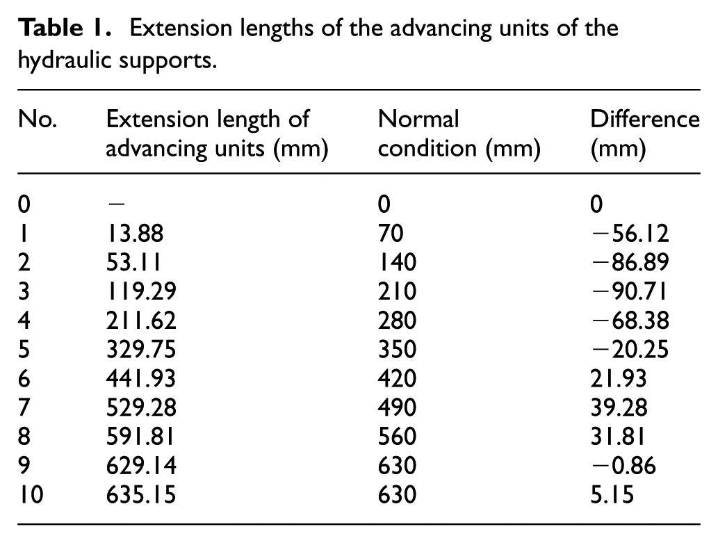
Assuming that the bending section is composed of nine segments, the pushing distances of the first and second sections are 1/9 times one stroke and 2/9 times one stroke, respectively. In reality, this regulation is not strictly met, and the calculated pushing length of the hydraulic supports must be modified by the proposed method to obtain a more realistic shape of the bending section. The calculation results are listed in Table 1.
Extension lengths of the advancing units of the hydraulic supports.
Experimental design
Design of the experimental device
Three machines in our laboratory were selected as the research objects. The type of the scraper conveyor was SGZ764/630, and its allowable bending angle was greater than 2°. The type of the shearer was MGTY250/600, and its cutting depth was 630 mm. The type of the hydraulic supports was ZZ4000/18/38, and it equipped electro-hydraulic control system and centralized control operation center, with which these three machines could be monitored remotely, and the S shape of bending section could be formed.
With the parameters of three machines, all parameters could be solved (Table 2).
Parameter selection.

Therefore, a prototype shearer and scraper conveyor whose sizes were 13.3% of the size of the original equipment were designed and manufactured. This enabled more convenient and faster experimentation. Using the scraper conveyor prototype, we were able to achieve the following: (1) variable shapes of the scraper conveyor could be formed; (2) in a different connection state of the middle troughs, the curve formed by the pin rails directly influenced the running trajectory of the shearer; (3) in a different connection state of the middle troughs, the contacting mode between the support sliding shoe and the coal plate could be simulated; and (4) a tilt sensor was installed in the middle position of every middle trough to mark the horizontal and vertical inclination angles in real time.
Using the shearer prototype, we could achieve the following: (1) the shearer body length could be changed; (2) coupled with the coal plate, the supporting sliding shoes could self-adapt; (3) two driving wheels were perfectly replaced by two tires, which could simulate the movement of the shearer; and (4) a strapdown inertial navigation system (SINS) device and a gyroscope sensor were installed in the position of the left supporting sliding shoe.
Experimental scheme
Experiments were performed on a prototype as described below:
The prototype chutes were bent and placed as determined in the theoretical calculation. The chutes prototype are marked and placed one by one with a long ruler and a marking line. The shape was corrected using the gyro angle and a strap-down inertial navigation system (MTi300), as shown in Figure 11(a).
From its initial state (no feeding and running), the running button of the shearer was clicked, and the prototype started running (see Figure 11(d)). During the running process, the shearer cutting walking trajectory and shearer body yaw angle were solved and recorded by the gyro angle meter and the strap-down inertial navigation device equipped in the machine body (see Figure 11(b)).
In five different shearer body length conditions (see Figure 11(c)), this experiment was carried out 20 times and the data collected in real time were analyzed.

Setup of the prototype experiment: (a) S-shaped bending section and measurement scheme, (b) sensors layout in shearer prototype body, (c) different shearer body length, and (d) shearer driving wheel.
The physical experiment was designed as follows:
The position and posture of the hydraulic support were adjusted, and all chutes before the center of all hydraulic supports were arranged in a straight line.
After pressing the start button in the remote control center, the advancing units of the hydraulic supports reached the length calculated by the automatic monitoring and control system in Table 1, and several points of the chute were measured, as shown in Figure 12(a). In Figure 12(c), the S-shaped bending section was composed from 9th chute to 17th chute. According to the data in Table 1, the extension lengths of the corresponding advancing units were controlled, and the control interface is shown in Figure 12(a). The bottom of this interface is the extension length of every advancing units.
A SINS device and a gyroscope sensor were installed in the position of the shearer body. Through the mine safety wireless base station, these data could be accessed by the monitoring host (see Figure 12(b)).

Operation interface of hydraulic supports and three machines: (a) interface of control system of hydraulic supports, (b) sensors layout in shearer body, and (c) S-shaped bending section.
Prototype experiment
The prototype experiments were carried out 10 times in a horizontal environment, and the operating conditions of the shearer prototype were measured and recorded by the gyro and strap-down inertial navigation system (see Figure 11). The change trend of the shearer yaw angle during the feeding process is shown in Figure 13 and Table 3.

Change trend of the shearer yaw angle during the feeding process.
Comparison between theoretical result and actual result.

The actual trend follows the theoretical trend, and the maximum error is 0.239°. The error is attributable to the Earth’s rotation, which affects the strap-down inertial navigation system and the gyro rotation angle. The first two conclusions obtained in the section “Calculation method of shearer yaw angle in the feeding process” were verified.
Physical experiment
Figure 14 compares the theoretical results and the actual curves obtained by the pin rails. After data processing and curve fitting, the theoretical and measured data are reasonably consistent and clearly express the relationships among the shape of the bending section of the scraper conveyor, the coordinates of the pin rails, and the running path of the shearer.

Physical experiment result: (a) the fitting curve of the measured data and the theoretical data and (b) error of two fitting curves.
After the analysis of mathematical fitting, there was a certain error (Figure 12(b)) between the actual results and the theoretical analysis results. The reasons may be the following:
The extension of the advancing units is not a strict linear motion, and the advancing units of all hydraulic supports, consisting of the advancing block and the pushing and pulling holes of the chutes, form a floating system. These factors were unaccounted for in the analysis and are responsible for the differences between the actual and calculated coordinates.
When a physical experiment was conducted, there was an error in the S-shaped bending section. After some analyses and observation, the reason was the actual difference between the laboratory environment and the underground environment. In the underground environment, the hydraulic supports were pushing the scraper conveyor in the condition of supporting roof and all the hydraulic supports are subjected to force. However, in the ground environment, when the hydraulic supports were pushing scraper conveyor, it was forced a reverse force from the scraper conveyor, and make them have some small backwards. It also caused a certain error.
Conclusions and prospects
The proposed method accurately calculates the various parameters in the bending section of the scraper conveyor, providing a theoretical basis for solving the postures of the three machines in the feeding process and realizing the automatic control of fully mechanized coal-mining equipment.
By providing a theoretical basis for the 3D positioning of three machines in a fully mechanized mining face, the proposed method can solve the shearer running track and accurately calculate the extension length of the advancing units of the hydraulic support. The relationships among the three machines in the running process can then be determined.
The analysis presumed some idealized conditions, such as a flat floor, ordered arrangement, and no biting or tilting of the hydraulic supports.
In future work, the formulation should account for more complex conditions, such as an uneven floor, various posture deviations of the hydraulic supports, longitudinal displacement of the chutes, and strong electromagnetic interferences. This work provides a mature solution that supports the 3D collaborative-related positioning of three machines in a fully mechanized coal-mining face.
Footnotes
Appendix 1
Handling Editor: Shun-Peng Zhu
Declaration of conflicting interests
The author(s) declared no potential conflicts of interest with respect to the research, authorship, and/or publication of this article.
Funding
The author(s) disclosed receipt of the following financial support for the research, authorship, and/or publication of this article: This work was supported by the merit funding for the returned overseas personnel sci-tech activities of Shanxi Province Grant No. 2016, Shanxi Postgraduate Education Innovation Project under Grant 2017BY046, Shanxi Scholarship Council of China under Grant 2016-043, and National Natural Science Foundation of China under Grant U1510116.