
Abstract
With the rapid development of trenchless technology, measurement-while-drilling systems draw extensive attention. At present, measurement-while-drilling systems are generally based on magnetic surveying technology or single-accelerometer measurement. In that case, the accuracies of these measurement-while-drilling systems are limited. In this article, a new measurement-while-drilling system with redundant accelerometers based on inertial technology is presented to improve the measuring performance of attitude, especially the measuring accuracy of roll. To reflect the influence of electromagnetic interference, the credibility estimation could be got by comparing the same attitude angles from the accelerometer and magnetometer. The calculation algorithm and experimental data are given in this article. Compared with traditional measurement-while-drilling systems, this new measurement-while-drilling system obtains better anti-disturbance property, higher measuring accuracy, and more reliable calculated results.
Introduction
The introduction of measurement-while-drilling system
Nowadays, the underground pipeline plays an important role in the municipal construction due to its versatile functions, such as water drainage, power supply, communication, and so on. The conventional open-cut methods, which were widely used for underground utility installation and replacement years ago, need to trench or destruct the entire ground surface where the pipeline should be installed. 1 Thus, using conventional methods is often associated with the interruption of traffic and influence on people’s daily life. As a result, the trenchless technology is developing rapidly in recent years. 2 The trenchless technology includes many construction or application methods, such as the horizontal directional drilling (HDD). With minimum need for ground trenches or excavation, these methods cause less inconvenience for urban management. In addition, with the improved construction efficiency, the cost will be substantially reduced.3,4
During the construction, however, engineers are unable to observe the construction progress directly. In order to guarantee a proper drilling procedure, a complete knowledge of the drilling bit’s orientation and position should be acquired in real time. 5 Therefore, the measurement-while-drilling (MWD) technology receives extensive attention. The so-called MWD technology is a method which could continually or discretely measure various parameters during drilling process. These parameters are concerned with the position information (drilling depth and trajectory) and the spatial attitude of the drilling bit. The spatial attitude includes (1) pitch, which reflects the inclination of the drilling direction relative to the horizontal plane; (2) roll, also known as tool face angle, which is the angular rotation of the drilling bit, when the drilling bit has an axially offset slanted face, it could reflect the direction change of the drilling trajectory in the next step; and (3) azimuth, which refers to the angle between the vertical projection of the drilling bit’s axis in the horizontal plane and the reference (such as the true north). If these parameters are available in real time, it is convenient to control the drilling process along the predefined trajectory. 6 Generally, measuring the spatial attitude of the drilling bit is the basic function for an MWD system.
A typical drilling tool used in trenchless technology is shown in Figure 1. It is generally composed of a drilling bit, an MWD system, and a non-magnetic drilling string for shielding magnetic interference in the surrounding environment. 7 The controllable drilling is illustrated in Figure 2; if the drilling bit is advancing and rotating, the drilling trajectory will follow the direction of the drilling string’s axis straightly. When we need to change the drilling direction, with the MWD system’s help, we could rotate the drilling bit’s slanted face so that the tool face angle is equal to the desired value. Then the drilling bit moves forward without rotating, the drilling trajectory will be bent due to the effect of reaction force. 8
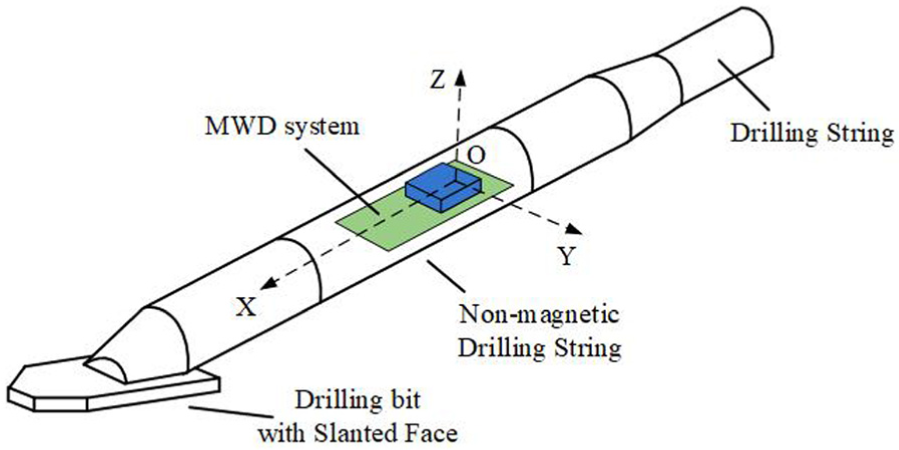
A typical drilling tool with MWD system.

Controllable drilling: (a) straight drilling and (b) bent drilling.
Defects of traditional MWD systems
At present, MWD systems are based on different measuring principles. A typical MWD system is based on magnetic surveying technology; its block diagram is shown in Figure 3. This system is composed of two parts: the underground while-drilling unit and the ground-monitoring unit. The former is used to measure drilling parameters. The magnetometer, which is fixed in the internal place of the while-drilling unit, gets the geomagnetic components. With these data, the attitude information of the drilling bit could be obtained in the attitude calculation and display device. However, the geomagnetic field is easily interfered by the surrounding environment, such as iron ore and electromagnetic device, which is the main drawback of this kind of MWD system.9,10 Besides, it results in increased cost due to the use of non-magnetic drilling string necessary for shielding the magnetometer. 11

A typical MWD system based on magnetic surveying technology.
The MWD system based on radiolocation principle has a radio transmitter in the while-drilling unit. The ground-monitoring unit, which is usually placed in drilling well entrance or the surface over the drilling trajectory, receives the radio signal and calculates the drilling bit’s position by radio intensity. Because of the radio transmitter’s limited power, this system could not be used in deep underground environment. The signal penetrability of radio transmitter subjects to the influence of stratum condition; as a consequence, the applications of this MWD system are limited. Furthermore, attitude information of the drilling bit is difficult to be measured accurately.
Recently, a new type of MWD system, which is based on inertial technology, is developed gradually. As shown in Figure 4, this MWD system has a 3-axis accelerometer and a 3-axis gyroscope. 12 During drilling process, the drilling bit’s acceleration and angular rotation are measured, so the position and attitude of the drilling bit are obtained through a calculation algorithm. Due to accumulated drift error of gyroscope, this MWD system frequently has degraded performance in long-term measurement. High performance gyroscopes, such as fiber-optic gyroscope, are generally characterized with high cost and large size. So they have limited usage in MWD system. 13 In order to measure the azimuth of the drilling bit, a magnetometer is added in some MWD systems. However, these systems do not obtain an effective data fusion between magnetometer and accelerometer.
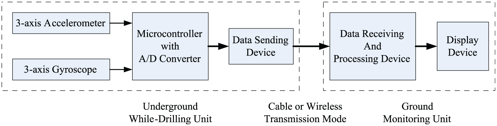
An MWD system based on inertial technology.
A new MWD system with redundant accelerometers
As discussed above, most of the MWD systems use magnetometer or single accelerometer to measure attitude angles of the drilling bit. However, these MWD systems usually have unsatisfactory performance in harsh drilling conditions. 14 Aiming at some defects of existing technology, this article presents a new MWD system based on inertial attitude measurement theory. This system is characterized with redundant multiple sensors. In order to improve the performance of MWD system, especially the measuring accuracy of attitude angles, two 3-axis accelerometers are used as redundancy to measure the acceleration of the drilling bit. To obtain the azimuth of the drilling bit, a 3-axis magnetometer is used to measure geomagnetic components. The credibility, which reflects the influence of electromagnetic interference on measuring accuracy, could be obtained by comparing the same parameters (roll, for example) measured by magnetometer and accelerometer. Combined with the calculation algorithm, the developed MWD system obtains good performance of measuring range, measuring accuracy, anti-disturbance ability, and so on.
System design
The MWD system discussed in this article is composed of two parts: (1) the while-drilling unit and (2) the monitoring unit. The while-drilling unit, which is installed inside of the drilling string, is the core component of the MWD system. It measures necessary parameters during drilling process. The ground-monitoring unit is the core of data processing and calculation, with which the motion state of the drilling bit could be displayed, and the essential data could be stored.
The while-drilling unit
The while-drilling unit is composed of a microcontroller, 3-axis accelerometer A, 3-axis accelerometer B, magnetometer, temperature sensor, and communication device. The block diagram is shown in Figure 5; each component’s function and design are as follows:

The block diagram of the MWD system.
As the core of the while-drilling unit, the C8051F120 microcontroller executes control commands, sends control signals to sensors, and completes data processing task. Two programmable A/D converters (12-Bit and 8-Bit, eight external inputs) are integrated inside of it. 15 With these A/D converters, the outputs of the sensors are converted to digital signals. Then, the processed data and other essential information are sent to the communication device through the Universal Asynchronous Receiver/Transmitter (UART) module.
Two micro-electro-mechanical system (MEMS) capacitive accelerometers LIS3L06AL are utilized to output the acceleration of the drilling bit. The measuring range of each chip is selectable at ±2 g/±6 g, which is enough in measurement while drilling, 16 and the output voltage is linear with the acceleration. Besides, it has the advantages of small size, simple circuit, and low power consumption. 17 In order to calculate pitch and roll of the drilling bit, the 3-axis accelerometer A is used to measure three mutually orthogonal components of the acceleration of gravity when the drilling bit is stationary. In addition, to get the drilling bit’s displacement, it is also used to measure the acceleration when the bit is moving. The 3-axis accelerometer B is added to calculate the attitude information (especially the roll angle) as redundancy. The detailed function and information about accelerometer B will be discussed in the following part of this article.
The HMC1053 magnetometer is designed to measure direction and magnitude of Earth’s magnetic fields. It is a high-performance magneto-resistive sensor and could be used in strong magnetic field environment. The advantages of this chip are orthogonal 3-axis sensing, miniature size, and wide field range of ±6 gauss. 18 In this system, three geomagnetic components from the magneto-resistive sensor are calculated to obtain the azimuth of the drilling bit and credibility estimation.
In order to provide temperature compensation for the output of the accelerometers, the DS18B20 1-wire digital thermometer is used to measure system’s temperature during the drilling process.
The power line carrier communication interface is designed as the communication module. In this communication method, the modulated signal is superposed and transmitted in the DC power line, in which case only two wires are needed. As a result, the anti-disturbance property of the system can be improved. 19 The communication module is composed of P485 transceiver IC, P111 power line media interface as the output power amplifier, and other assist components. It is worthwhile to note that sensors and microcontroller might be affected by the electromagnetic noise caused by the power line carrier communication interface, so the communication module should be shielded in a grounded metal shell as shown in Figure 5. 20
In addition, in order to guarantee the measuring accuracy, a high precision power module, which provides stable analog and digital power supply, is included in the while-drilling unit.
The monitoring unit
The monitoring unit is composed of Advanced RISC Machine (ARM) 9 system, LCD, communication interfaces, and other modules. The block diagram is shown in Figure 5.
The ARM 9 system is the core of the monitoring unit. It is based on S3C2416 16/32-Bit microprocessor which is designed to provide hand-held devices and general applications with low-power and high-performance microcontroller in small size. This ARM 9 system has 64M SDRAM, 64M FLASH, two UARTs, USB module, LCD interface, and so on. In addition, this system supports WinCE operating system as well as UNIX, so it is suitable for portable devices. With measuring information from the while-drilling unit, the attitude and position of the drilling bit are calculated in S3C2416 microprocessor. Moreover, the temperature compensation is applied to improve the measuring accuracy.
The interaction device is comprised of LCD and keyboard. The final results calculated by microprocessor are displayed in the LCD in real time. The dynamic displayed information includes the attitude information (pitch, roll, and azimuth), displacement information (three axial displacement and total displacement of the drilling bit), and additional graphic information. The keyboard has multiple function press keys which could switch displayed information and control the whole MWD system.
Meanwhile, in the monitoring unit, the interfaces include (1) power line carrier communication interface to transmit information between the while-drilling unit and the monitoring unit, (2) RS232, and (3) USB interfaces to transmit data to PC or other devices for further processing.
Installation of redundant accelerometers
The traditional MWD system uses the data measured by single accelerometer to calculate the attitude information of the drilling bit. When pitch is close to ±90°, the calculated result of roll usually has a great error due to the presence of noise. To avoid this defect, the 3-axis accelerometer B is added in the system as redundancy.
The accelerometer A is fixed on the main circuit board along the directions of the carrier coordinate system. And the accelerometer B is fixed on the daughter-board which is connected to the main circuit board slantedly. Using redundant accelerometers, which measure three mutually orthogonal components of the acceleration of gravity in two different reference coordinate systems, respectively, enhances the performance of anti-interference and improves the measuring accuracy. In order to differentiate two data groups measured by two accelerometers availably, the angle between two installation planes of accelerometers should be appropriate. As a consequence, the angle between the planes of the two boards is 45°, and the angle between the bottom edge of the daughter-board and the edge of the main board is also 45°. The concrete design is shown in Figure 6.
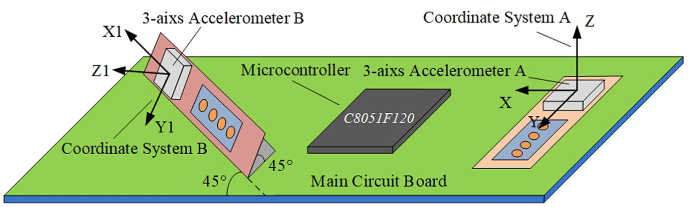
The installation of redundant accelerometers.
The calculation algorithm of attitude and drilling trajectory
The calculation algorithm, which is the key of the data processing in the MWD system, includes temperature compensation, angle calculating, dead reckoning, and credibility estimation. The detailed contents of each part are given below.
The definitions of the coordinate systems and attitude angles
In order to get the attitude angles, reference coordinate systems are defined in this article. These coordinate systems include the geographic coordinate system (GCS), the carrier coordinate system A (CCS-A), and the carrier coordinate system B (CCS-B). Three axes of the GCS point to the directions of the East (E), North (N), and up (U), respectively. The origin of the CCS-A is located in the place where the accelerometer A is fixed. Its X-axis refers to the forward direction of the bit’s axis. In the cross section of the bit, from the view of the positive direction of the X-axis, the Y-axis refers to the direction of the boring tool face, and the Z-axis refers to the direction orthogonal to X-axis and Y-axis. The three axes of CCS-A conform to the right-hand rule.
The MWD system measures the attitude of the drilling bit, which consists of pitch, roll, and azimuth. Pitch refers to the acute angle between the X-axis of CCS-A and the horizontal plane. Roll is defined as the angle of Z-axis of CCS-A in relation to vertical direction in the plane perpendicular to the X-axis of CCS-A. The azimuth is the angle between the vertical projection of the X-axis in the horizontal plane and the N-axis of GCS. The relationship between GCS and CCS-A is illustrated in Figure 7. Meanwhile, pitch (θ), roll (γ), and azimuth (φ) are also shown in Figure 7.
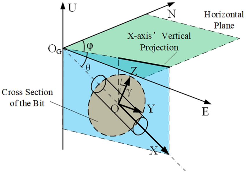
The definitions of GCS, CCS-A, and the attitude angle.
In addition, the accelerometer B has CCS-B. According to the installation relationship between two accelerometers, the CCS-B could be obtained through coordinate rotating from CCS-A. First, the CCS-A is rotated 45° around the Z-axis. Then, it is rotated 45° around the X-axis. Both rotations are clockwise. The relationship between CCS-A and CCS-B is illustrated in Figure 8.
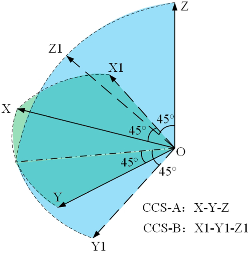
The relationship between CCS-A and CCS-B.
The temperature compensation
Installed inside the drilling string, the while-drilling unit could be affected by the heat produced by the drilling bit’s working. So the measuring accuracy is usually unsatisfied. The influences of temperature on the performance of inertial devices are as follows: (1) The measuring error might be caused by the fluctuation of the environment temperature around inertial devices. (2) The thermal expansion of materials may cause the component deformation and disturbing torque. (3) The physical parameters of the device might be changed because of temperature fluctuation. 21 As a result, it is important to take into account the influence of temperature on the accelerometer’s output.
The actual output of accelerometer is defined as

where
The calculation algorithm of the attitude angle
As shown in Figure 9, with the output from single accelerometer, the pitch (


The calculation of the dip angle.
Roll could also be calculated as
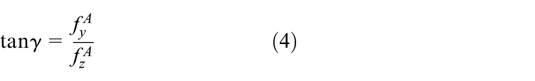
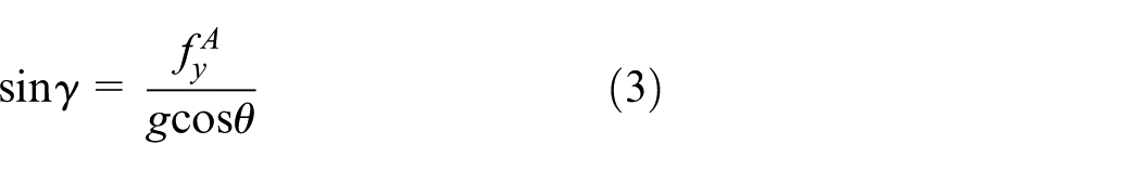
where g is the acceleration of gravity,
From equation (3), we can see that if
In order to improve the performance of MWD system, the following method is used: if
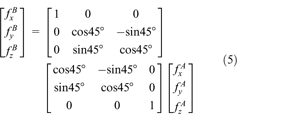
where
From equation (5), we could get

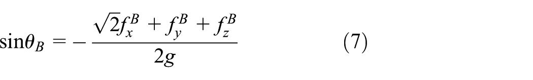
Combining equations (2), (4), and (6), using the data from the accelerometer B, the calculation of pitch (

Although the rotation of drilling string can produce centrifugal force, which will seriously interfere with the operation of accelerometers, rotational speed compensation can eliminate these influences by calibrating the accelerometers in advance. 22
The calculation algorithm of the direction angle
As shown in Figure 10(a), with three geomagnetic components in the CCS-A from the magnetometer,


The calculation of the azimuth.
With

where
Meanwhile,

where
The credibility estimation of electromagnetic interference
The accuracy of azimuth is bound up with the output error of magnetometer. Due to the strong interference during the drilling process, the data from the magnetometer usually has uncertain error. Therefore, it is essential for MWD system to give a definition of credibility which reflects the intensity of electromagnetic interference on measurement of azimuth. The credibility estimation proposed in this article is shown as follows:
When the drill is stationary, pitch (

Or

where
The calculation algorithm of the dead reckoning
In trenchless technology, the drilling trajectory of the drilling bit is an essential parameter for engineers. As shown in Figure 11(a), in order to acquire the entire drilling trajectory, the trajectory is divided into a series of segments, and each small segment could be seen as a straight line approximately. The displacement of each segment is calculated through twice integration with the output of the accelerometer. Combined with the attitude information (

where i is the sequence number of the segment,

The calculation algorithm of the dead reckoning.
Accumulating the displacement of each segment, the complete trajectory of the bit could be got. With the length of standard drill pipe, the length of the drilling trajectory could be calibrated at special points to improve the measuring accuracy of the bit’s position.
In dynamic measurement, the interaction between drilling string and wall, drilling bit, and rocks will produce complex vibration which mainly contains twisting vibration, lateral vibration, and longitudinal vibration. The outputs of accelerometers will not be accurate because of the vibration. Factors that influence the vibration are various and time-varying. However, statistical regularity exists in various vibrations overall. The regularity cannot be described by functions related to time, but it can be described by probability theory and statistics. Therefore, we can obtain the frequency spectrum of the vibration signals through power spectral density function of accelerometer output in vibration circumstance, and an appropriate low-pass filter, which is usually a Butterworth filter with certain orders and cutoff frequency, is designed to eliminate the influence of vibration and ensure the accurate measurement. 22
Experiments and tests
Single-accelerometer tests
In order to test the measuring accuracy of MWD system with single accelerometer, we use accelerometer A to calculate attitude angles (pitch and roll) of the drilling bit. Figure 12 shows the while-drilling unit and the monitoring unit. As a guard, the pipe is filled with soft rubber which can immobilize and protect the circuit board from mechanical vibration. The two ends of the pipe are sealed so that the system is waterproof. The experimental circuit of accelerometer A is fixed on a 3-axis turntable which could adjust attitude angles conveniently. Figure 13 shows experiment process on the MWD. The while-drilling unit is fixed on the 3-axis turntable whose measurement accuracy is 0.05°, and the monitoring unit displays pitch and roll.
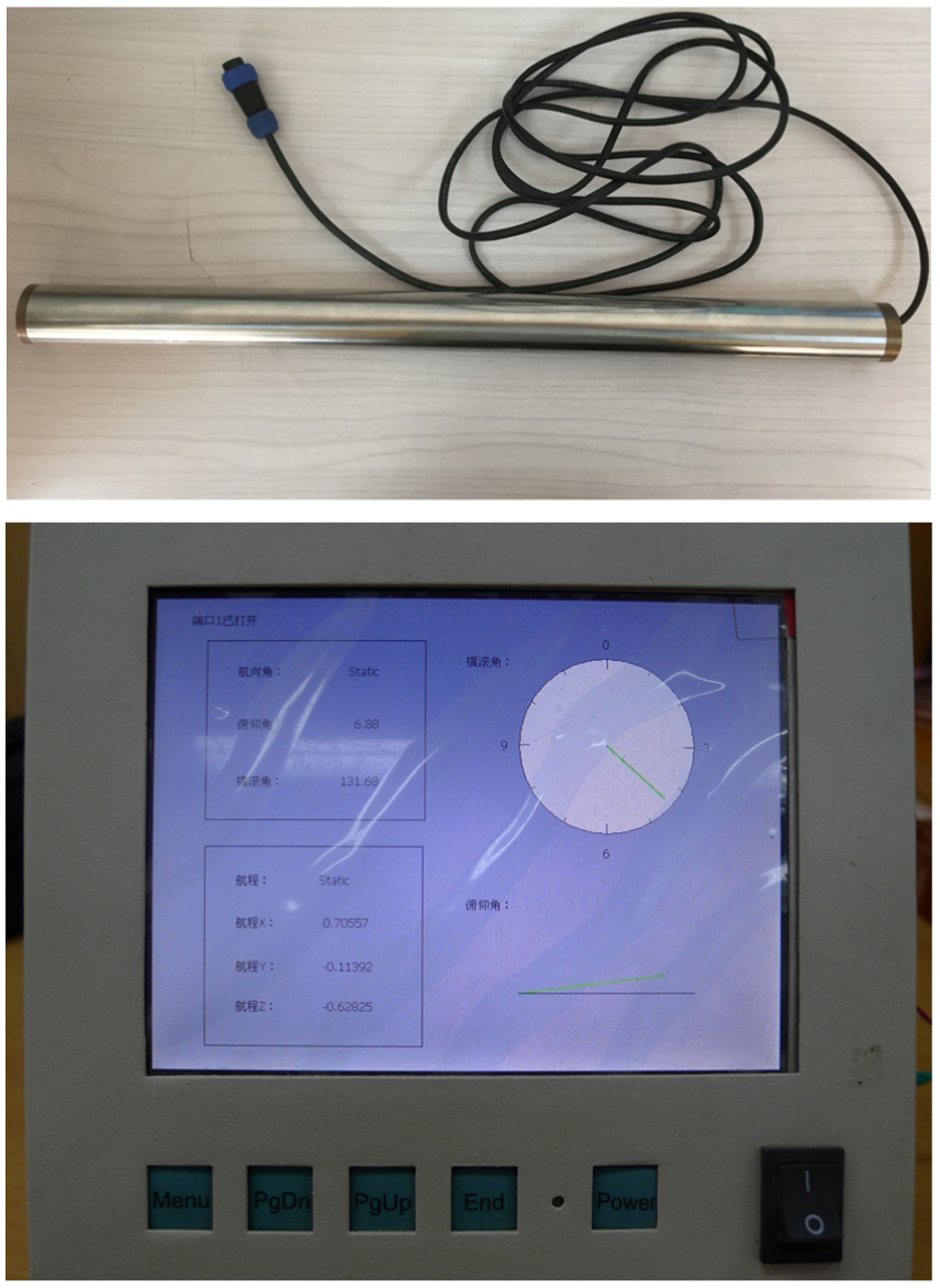
The while-drilling unit and the monitoring unit.

Experiment on the MWD.
To test measuring accuracy, the stationary experiments are divided into two steps.
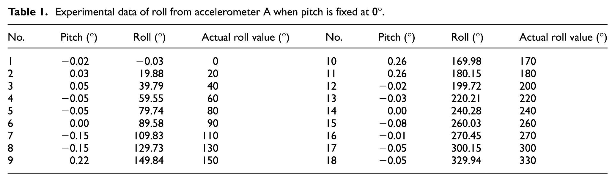
a. Stationary Experiments of Roll: fixed pitch angle at 0°, adjust the 3-axis turntable to change roll gradually. The experimental data are given in Table 1. From Table 1, we can see that the measurement error of roll is less than 0.5°. Meanwhile, the measurement error of pitch is less than 0.3°.
b. Stationary Experiments of Pitch: fixed roll angle at 0°, adjust the 3-axis turntable to change pitch gradually. The experimental data are given in Table 2. The measurement error of pitch is less than 0.5°. Meanwhile, when pitch is no more than 80°, the measurement error of roll is less than 0.7°. From Table 2, the calculated results of roll are 85.45° and 11.11° when pitch is ±90°, respectively. However, the actual value of roll is 0°, so the measurement error is extremely large due to the interferences in this situation.
Experimental data of roll from accelerometer A when pitch is fixed at 0°.
Experimental data of pitch from accelerometer A when roll is fixed at 0° (180°).

To research the influences of interference or noise on the measurement errors of roll angle, the experimental circuit is fixed at different pitch angles to test the fluctuation of roll from accelerometer A. At each pitch angle, the experimental circuit is stationary, and the calculated results of pitch and roll are recorded once per second. Each test will last 30 s. Several test results are shown in Figure 14. In addition, the standard deviations of each test are shown in Table 3. From Table 3, we can conclude that the calculated results of pitch did not fluctuate significantly at different pitch angles. This phenomenon indicates that the interference (or noise) intensities of these tests are at some level approximately. The calculated results of roll, however, are much different. When pitch is between −60° and 60°, the fluctuations of roll caused by interference or noise are at small level. But the fluctuations of roll are much more dramatic with the increment of pitch when pitch is larger than 60° (less than −60°). So the accuracy of MWD system with single accelerometer is unsatisfied.
The standard deviations of tests at different pitch angles.


Experiment data at different pitch angles: (a) pitch is 0°, (b). pitch is 45°, (c) pitch is 80°, (d) pitch is 85°, (e) pitch is 90°, (f) pitch is −90°, (g) pitch is −85°, and (h) pitch is −80°.
Dual-accelerometer tests
To improve the measuring accuracy of attitude, especially the accuracy of roll, the accelerometer B is added in the MWD system. Tests are divided into two steps:
a.
b.
Calculated results of dual accelerometer when pitch is less than 45°.

Roll: the calculated results of roll from accelerometer B is used as the final results. When pitch is fixed at ±80°, ±85°, and ±90°, respectively, the experimental data are shown in Figure 15.

Calculated results of roll when pitch is ±80°, ±85°, and ±90°: (a) pitch is 80°, (b) pitch is −80°, (c) pitch is 85°,(d) pitch is −85°, (e) pitch is 90°, and (f) pitch is −90°.
The standard deviations of these tests are shown in Table 5. Compared with single accelerometer, the standard deviations of roll with dual accelerometer decrease sharply. So the fluctuations of roll maintain small level which approaches the fluctuation level when
The standard deviations of tests with single accelerometer and dual accelerometer.

Contrast with industry approaches
Different industry-standard approaches develop constantly at present, and they are widely applied in MWD. Electromagnetic MWD and MWD system utilizing single accelerometer are playing critical roles in this field. Although they perform well in most measurement situations, they still have shortages in some aspects such as anti-disturbance and measurement accuracy. The advantages of the new MWD system proposed in this article are embodied after comparing with those of industry approaches.
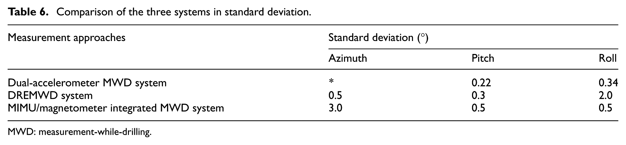
First, we take Electromagnetic wave DREMWD system introduced in literature 23 as an example. As described, electromagnetic wave technology is applied in this system. However, the geomagnetic field is easily interfered by the surrounding environment, such as iron ore and electromagnetic device. The measurement result will be unreliable under such circumstances. By contrast, the dual-accelerometer MWD system based on inertial attitude measurement theory successfully addresses this problem. At the same time, the credibility, which reflects the influence of electromagnetic interference on measuring accuracy, could be got by comparing the same parameters (roll, for example) measured by magnetometer and accelerometer. Thus, the developed MWD system obtains good anti-disturbance ability. As far as we can see, the low-cost Miniature Inertial Measurement Unit (MIMU)/magnetometer integrated MWD system in literature 24 is a typical MWD system equipped with single accelerometer. In this system, a single accelerometer is utilized to measure the system’s attitude. Inevitably, the tool face angle will fluctuate acutely when pitch is close to ±90°. However, this problem will not appear in the dual-accelerometer MWD system. Comparison of the above mentioned systems in standard deviation is shown in Table 6.
Comparison of the three systems in standard deviation.
MWD: measurement-while-drilling.
The accuracy of azimuth is bound up with the output error of magnetometer and the credibility estimation of azimuth is given in section “The credibility estimation of electromagnetic interference.” The measurement accuracy of dual-accelerometer MWD system is much better than the other two systems, which proves that dual-accelerometer MWD system has certain advantages in measurement accuracy.
Conclusion
Aiming at the defects of existing technology, a new MWD system based on inertial technology is proposed in this article. This MWD system is characterized by two redundant accelerometers which are fixed at two different planes. To improve the measuring accuracy, the calculated results from two accelerometers are fused to get the final results of attitude angles. When pitch is close to ±90°, the calculated results of roll from accelerometer B are used as the final results. To reflect the influence of electromagnetic interference, the concept of credibility is also provided.
This new MWD system can be equipped in drilling tool and completes measurement of azimuth, pitch, and roll, simultaneously. Results from experiments and tests indicate that the measurement error of pitch is less than 0.22°, and the measurement error of roll is less than 0.34°. Particularly, compared with MWD system utilizing single accelerometer, this new MWD system has fine performance when pitch is close to ±90°. Although based on experiments and tests, the proposed new MWD system in this article has strong anti-interference ability and high measuring accuracy compared with the existing industry approaches. In this new MWD system, factors such as high pressure and vibrations should be considered and studied for satisfactory performance in drilling process. When conditions are available, the system needs to be verified and improved in a real application of the MWD.
Footnotes
Handling Editor: Francesco Massi
Declaration of conflicting interests
The author(s) declared no potential conflicts of interest with respect to the research, authorship, and/or publication of this article.
Funding
The author(s) disclosed receipt of the following financial support for the research, authorship, and/or publication of this article: This work was supported by the National Natural Science Foundation of China (No. 61573059).