
Abstract
To improve the performance of the cone bit bearing seal, experimental study and simulation analysis of seal failure were carried out, and optimization of the seal was conducted. Results show that damages are located on the shoulder of the rubber rings due to high shear stress caused by large compression ratio, and serious wear appears on the sealing face of the metal rings because of unreasonable contact pressure distribution. Optimization was conducted by finite element method on three aspects: the dip angles (3°–8°) of the sealing face, the widths (1.3–3.9 mm) of the sealing face, and the back support structure (10°–15°). These three aspects were optimized one by one. Each aspect was optimized by different values, with the average compression ratio and the contact pressure distribution of the sealing face acting as evaluations. The optimal value of the previous optimization step performs as the static value in the next step, and finally, the optimized structure was selected from the last step. The performance of the optimized seal is significantly improved. The compression ratio of the optimized seal rubber drops to less than 14%. The wear mount of the new structure reduces to 20%–38% of the original structure.
Keywords
Introduction
Cone bit is the main rock-breaking tool in oil and gas drilling engineering, whose performance and service life directly affect the quality of the well, the drilling efficiency, and the drilling cost. The bearing seal is a critical and vulnerable part of the cone bit, which significantly affects the service behavior of the bit.1,2 About 80% of roller cone bit failures are due to the failure of the bearing system, and early seal failures bring about 30% of bearing failures.3,4
The development of the cone bit bearing seal has gone through a long process. In 1985, the metal seal appeared in the cone bit bearing seal system. 5 After that, many investigations and applications showed the superiority of the bimetal seal, which brought significant economic benefits to the drilling industry.6–8 Chen analyzed the force and working environment of the cone bit, considered that the early failure of the rubber seal was severe, and proposed to use polytetrafluoroethylene as the sealing material. 9 Luo et al. 10 conducted an experimental study of the metal seal and pointed out that the seals effectively adapted to the vibration conditions and had the advantages of low leakage and long service life under high speed conditions. Baker Hughes developed the second-generation single energizer metal seal (SEMS) with a new metal seal system. Compared with conventional radial rubber seal and SEMS bit, an increase of 47% and 38% in average service life, respectively, was achieved using the second-generation SEMS cone bit.11,12 Griffo and Keshavan 13 developed a seal with fiber technology containing nanoparticles to improve the sealing performance. In 2009, Chen and Chen 14 applied plasma spraying technology on the metal ring surface, and results showed that the surface wear resistance ability and bit life were enhanced. Zhang et al. 15 improved the second-generation SEMS with a custom-shaped rubber seal ring; his investigation found that softer rubber material can obtain greater sealing force, thus reducing the opening between conical surfaces and the rubber ring and keeping the seal within satisfactory performance. Suto and Hiroshi 16 investigated the effects of the load condition on frictional heat and temperature within a cone bit and found that the temperature within the bit increased readily due to insufficient lubrication. Although the cone bit seal has been constantly improved, the failure situation is still a serious problem. Failure analysis is helpful to understand the process and causes of seal failure. So the optimization of the seal will be more reasonable and reliable based on the failure analysis, which is conducive to effectively develop a better cone bit bearing seal.
In this article, experimental study and simulation analysis were carried out to determine the location and causes of sealing failure. Based on the failure analysis, the sealing structure was optimized from three aspects: the dip angle of the sealing face, the width of the sealing face, and the back support structure. A comparative investigation of the original seal and the optimized seal was conducted on contact pressure distribution, average compression ratio of rubber rings, and wear of metal rings. Results show that the optimized seal has a better performance with more reasonable contact pressure, lower average compression ratio, and less wear, which are beneficial to improve the service life of the seal.
Failure analysis of the seal
Seal structure
As shown in Figure 1, the typical bimetal seal which is located in the chamber between the cone and the bearing consists of a pair of metal rings and a pair of rubber rings. The two rubber rings always keep the faces of the two metal rings in contact, thereby forming a reliable seal and also playing the role of a radial seal. The function of the cone bit bearing seal is to prevent mud, cuttings, and other substances from entering into the bearing and to maintain the grease acting as lubricant.

Cone bit bearing seal: 1—shaft contour, 2—static rubber ring, 3—static metal ring, 4—moving metal ring, 5—moving rubber ring, and 6—cone inner contour.
Failure analysis of the seal
Experimental study
Rubber rings
Figure 2 demonstrates the appearance of the failed rubber rings. The loads acting on the seal system were drilling fluid pressure and the grease pressure. The lubrication condition was grease lubrication. The working time was less than 100 h. All seal rings were seriously damaged with a lot of wear and tears. There was a deep furrow on the shoulder of every rubber ring. When the bit was working downhole, the mud and small cuttings entered into the seal chamber due to the gap fit between the roller and the shaft, exacerbating the wear of the rubber rings. Images (a) and (b) show that the furrow developed from the shoulder to the sides and finally spread to the entire contact surface.

Failed rubber rings: (a) and (b) moving rubber rings; (c) and (d) static rubber rings.
Figure 3(a)–(d) are local magnifications of the furrows of (a), (b), (c), and (d) in Figure 2, respectively. The damages of the rings develop along the circumferential direction (as the arrows show). The main failure are lamellar features (in the solid line boxes), and a large number of rubber material peels off from the body. Under the action of loads and motion, fatigue cracks originate from the wear and cracking and gradually expand to form lamellar features. Then the rubber peels off from the body, resulting in seal failure. The seal surface is very rough that there are a lot of groove marks (in the dashed line boxes). The material of the sealing ring is nitrile rubber, which is a high elastic material that can change its size and shape under the action of external forces and bear reversible deformation. 17 Usually the seal ring is installed in the seal groove according to a certain compression ratio, and the general compression ratio ranges from 10% to 20% for dynamic seals. 18 Too small of a compression ratio leads to failed sealing. Too large of a compression ratio brings large contact stress, which accelerates the surface wear. Moreover, a large compression ratio results in severe compression deformation and high shear stress, causing wear and cracking.
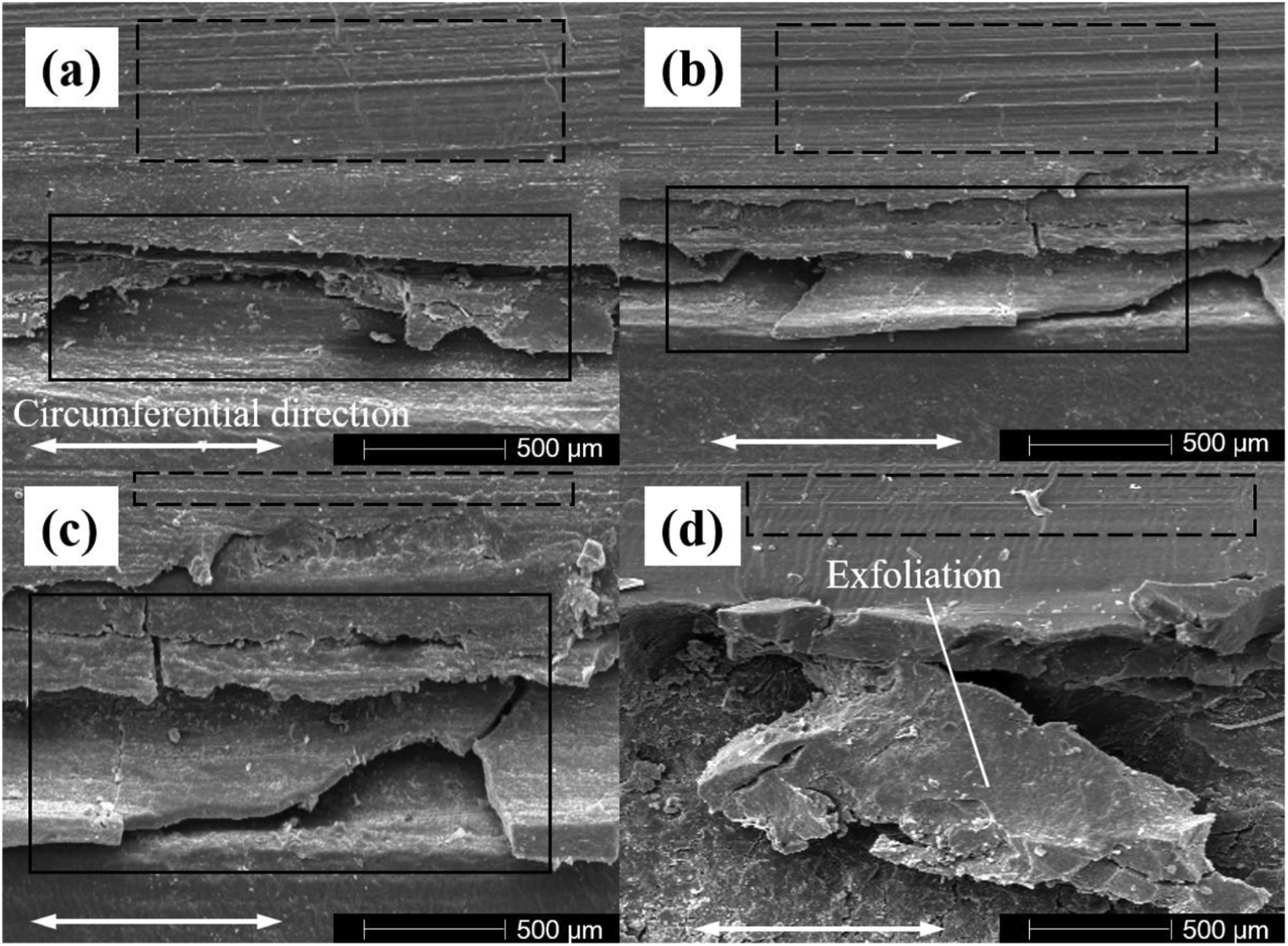
Local magnifications of the furrows shown in Figure 2.
Metal rings
The main wear of the metal rings mainly concentrates in the inner side of the end face, while the wear of the other area is less, as Figure 4 shows. The grease was not evenly distributed over the entire sealing surface of the static metal ring. Since the moving metal ring is rotating, its sealing surface can be exposed to the lubricant, but the static metal ring is not lubricated evenly. So the wear of the moving metal ring is almost of axial symmetry, but the wear of the static metal ring is not. There are many black stains on the sealing surfaces, indicating that the grease did not play a good role in lubrication. The wear of the moving metal ring is greater than that of the static metal ring. This is because of unreasonable contact pressure distribution due to unqualified seal surface structure. A reasonable pressure distribution on the sealing face should be a low pressure on the inside and a high pressure on the outside. A reasonable pressure distribution can bring such benefits: (1) a low pressure on the inside can make the grease easily enter into the sealing face and act as a lubricant; (2) a high pressure on the outside can prevent the abrasives such as mud and cuttings from entering the sealing face. If the seal structure can perform with reasonable pressure distribution, the seal structure is qualified, otherwise it is unqualified. Unqualified seal surface structure brings unreasonable contact pressure distribution in that the contact pressure of the inside is higher than that of the outside, resulting in wear of the metal rings.
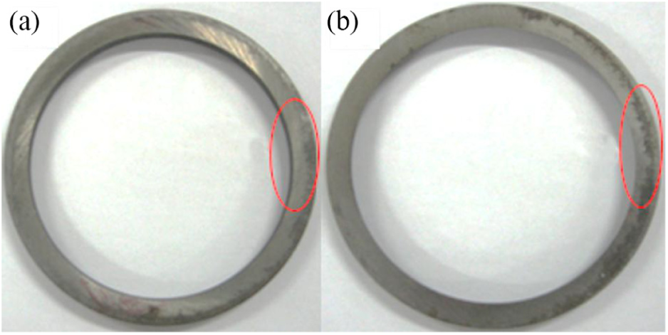
Wear of the metal rings: (a) moving metal ring and (b) static metal ring.
Simulation analysis
The simulation was conducted by finite element method with ANSYS software. Since the seal is an axisymmetric structure, a two-dimensional simulation model of the seal was established as shown in Figure 5. The sealing face is the red line. Inside means the area of the sealing face is close to the inner diameter of the moving metal ring, and outside means the area is close to the external diameter of the static metal ring. Both the structure and the boundary were treated as axial symmetry. This process greatly reduced the computational complexity, but resulted in an adequate accuracy.

Two-dimensional simulation model of the seal.
The material and size of the simulation model were consistent with the actual situation. The material of the metal rings is 9CrW18Mn, which is considered as a linear elastic and isotropic material. The elastic modulus is 2 × 10¹² Pa and Poisson’s ratio is 0.3. The material of rubber rings is nitrile rubber, which is considered as nonlinear and hyperelastic. The constitutive model of rubber is described as Mooney-Rivlin five-parameter model. 19 In the constitutive model, the five parameters C10, C01, C11, C20, and C02 are 7.2668, –4.587, 3.353, –2.187, and 0.6986, respectively. HYPER74 element was used to simulate the rubber material. The HYPER74 element is applicable to nearly incompressible rubber-like materials with arbitrarily large displacements and strains.
The seal is meshed with quadrilateral elements, and the size of the element is 0.2 mm. The number of load sub-steps is 150, while the maximum number of load sub-steps is 1000 and the minimum number of load sub-steps is 100. Force balance is set as convergence criterion. The element can be used either as a biaxial plane element (plane strain) or as an axisymmetric ring element. The friction coefficient between the metal rings is 0.1, and the friction coefficient between the rubber ring and metal ring or cone is 0.2. The application of the load was divided into two steps. The first step was to simulate the assembly process of the seal. The second step was to simulate the stress and strain of the assembled seal structure with a changing seal chamber pressure ΔP. ΔP is the pressure difference between the drilling fluid and the grease on both sides of the seal, which ranges from 0.3 to 0.7 MPa as measured downhole.20,21 The pressure difference is applied on the top of the moving ring.
Shear strain of the rubber rings
Figure 6 shows the shear strain of the rubber rings at a minimum pressure difference of 0.3 MPa and a maximum pressure difference of 0.7 MPa. The maximum shear strain of the moving rubber ring or the static rubber ring is at its shoulder, which is also the main part of its failure as experimental study indicates. As the pressure difference ΔP increases, the shear strain also increases. Larger shear strain means greater risk of cracking. This shear strain is mainly caused by compression. The compression ratio of the moving rubber ring and static rubber is 27.51% and 31.60%, respectively, as ΔP is 0.3 MPa. When ΔP is 0.7 MPa, the compression ratio of the moving rubber ring and static rubber is 27.11% and 33.00%, respectively. So the compression ratio is a very important indicator for rubber ring analysis.

Shear strain of the rubber rings: (a) ΔP = 0.3 MPa and (b) ΔP = 0.7 MPa.
Stress distribution
Von Mises stress distribution of the seal is demonstrated in Figure 7. The maximum stress concentrates on the contact surface of the moving metal ring and the static metal ring near the side of the conical tip, and this is where the most serious wear happens. On the sealing face, the stress distribution on the inside is much higher than that on the outside. When the moving metal ring rotates around the shaft, abrasive wear occurs between the metal ring and the cuttings attached to the sealing surface. As a result, the wear of the moving metal ring on the inside is severe under the action of abrasive and high pressure. The stress distribution indicates that the structure of the sealing face is incompetent.

Stress distribution of the seal: (a) ΔP = 0.3 MPa and (b) ΔP = 0.7 MPa.
Experimental study and simulation analysis indicate that the failure of the rubber rings is different from that of the metal rings. The failure of the rubber ring is due to large shear strain as the compression ratio is too high, and the main reason for the wear of the metal ring is unreasonable stress distribution because of sealing structure. Therefore, the optimization of the new sealing structure was carried out based on these two evaluation indexes.
Optimization of the seal
Dip angle of the sealing face
As shown in Figure 8, α is the dip angle of the sealing face. Without changing other parameters of the seal, we, respectively, took α as 3°, 4°, 5°, 6°, 7°, and 8° to study the contact pressure distribution on the sealing face.
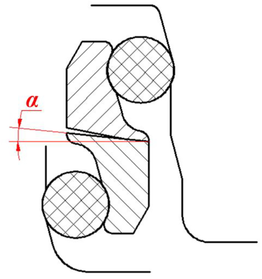
The dip angle of the sealing face.
Reasonable contact pressure distribution should be that the inside of the sealing face pressure is low while the outside pressure is high. This pressure distribution is helpful for the grease to enter the sealing face from the inside and blocking mud and cuttings from the outside. Figure 9 shows the contact pressure distribution of the sealing face with different dip angles. In Figure 9, inside means the side of the sealing face near the shaft or the inner diameter of the metal rings, and outside indicates the side close to the cone or the external diameter of the metal rings, as they are also shown in Figure 5. The contact pressure distribution with dip angles of 3°, 4°, 7°, and 8° is that the inside pressure is great while the outside pressure is almost zero. Such distribution does not satisfy the reasonable pressure distribution, so we do not choose these four angles. The contact pressure distribution with dip angles of 5° and 6° is in line with reasonable distribution. The maximum value of the contact pressure with a dip angle of 5° is 50.44 MPa, and the maximum pressure with a dip angle of 6° is 14.99 MPa. High contact pressure means serious wear of the metal rings. At the same time, the pressure distribution gradient of the sealing surface with a dip angle 6° is gentler. Therefore, the selected dip angle is 6°.

Contact pressure distribution of the sealing face with different dip angles: (a) α = 3°, (b) α = 4°, (c) α = 5°, (d) α = 6°,(e) α = 7°, and (f) α = 8°.
Width of the sealing face
After the optimization of the dip angle, the contact pressure is more competent but still high. In order to obtain a better pressure distribution, we optimized the width of the sealing face L with a dip angle of 6° as shown in Figure 10. The width of the original sealing surface is 1.3 mm. We took L of 1.4, 1.9, 2.4, 2.9, 3.4, and 3.9 mm, respectively, to study the relationship between L and the contact pressure.

The width of the sealing face.
As shown in Figure 11, when L is 1.4, 1.9, 2.4, and 2.9 mm, respectively, the contact pressure distribution of the sealing face is larger inside than outside. This trend is not what we want to design. The maximum pressure in plot (f) is higher than that in plot (e). When L is 3.4 mm, the maximum contact pressure is 6.302 MPa. The maximum contact pressure is 17.6 MPa when L is 3.9 mm. The maximum contact pressure drops significantly with 3.4 mm of width, which is conducive to reduce wear. Therefore, it is more appropriate to choose 3.4 mm as the width of the sealing face.

Contact pressure distribution of the sealing face with different widths: (a) L = 1.4 mm, (b) L = 1.9 mm, (c) L = 2.4 mm, (d) L = 2.9 mm, (e) L = 3.4 mm, and (f) L = 3.9 mm.
Back support structure
Compression ratio is the main factor affecting the service life of the rubber rings. 18 In order to reach an appropriate compression ratio, the improvement of back support structure was carried out on the basis of the above optimization of the sealing face. The key parameter of the back support structure is the back supporting angle δ as illustrated in Figure 12. The radius of the two rubber rings was increased to reduce the compression ratio. And the radius of both rubber rings was equal. The supporting angle δ was taken as 10°, 11°, 12°, 13°, 14°, and 15°, respectively, for study to obtain better pressure distribution and compression ratio.
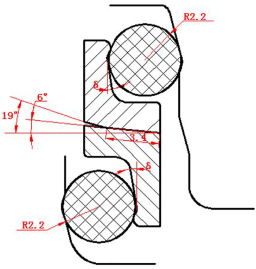
Seal structure after optimization of dip angle and width of the sealing face.
Since the contact pressure distribution of different δ is consistent, we only show the amplitude, as shown in Figure 13. A distance of 0.00 and 3.40 mm represents the inside edge and the outside edge of the sealing surface, respectively. The pressure distribution trend of the six angles is consistent, that is, the outside is high and the inside is low. The pressure gradually increases from the inner diameter to the outer diameter. When the inclination angle is 11°, the maximum contact pressure is 6.41 MPa, which is the smallest one of six angles. Even so, it is difficult to determine which angle should be chosen. Therefore, we further analyzed the average compression ratio under different angles. Figure 14 shows the directions of the compression ratio of the two rubber rings that are calculated. Since the deformation of the rubber ring is nonlinear, the average value is calculated.

Contact pressure distribution of different back supporting angles δ.

Calculating directions of average compression ratio of the rubber rings: (a) moving rubber ring and (b) static rubber ring.
Figure 15 shows the average compression ratios of the two rubber rings with different back supporting angles when ΔP = 0.7 MPa. All average compression ratios are in the range from 10% to 20%. The average compression ratio with back supporting angles of 10° and 11° is less than 15%. When the angle is 11°, the difference of the compression ratio between the two rubber rings is only 0.4%, which is beneficial for the moving rubber ring and the static rubber ring to maintain same service life. Considering the pressure distribution and the compression ratio, we selected the back support structure with a back supporting angle of 11°.

Average compression ratios of the two rubber rings with different back supporting angles (ΔP = 0.7 MPa).
New seal structure
Figure 16 demonstrates the seal structure before optimization and the seal structure after optimization. Specific optimization parameters are demonstrated in Table 1.

Seal structure: (a) original structure and (b) optimized structure.
Optimization parameters.

Results and discussion
Comparison of average compression ratio
Figure 17 shows the average compression ratio of rubber rings under different ΔP. The average compression ratio changes very little for different ΔP. For the original seal, the average compression ratio of the moving rubber ring is more than 27% and the ratio of the static rubber ring is more than 31%. The difference between them is more than 4%. Compared with the original seal, the average compression ratio of the optimized seal rubber rings drops. The value is less than 14% and within the reasonable range of 10%–20%. And the difference between the two ratios of rubber rings is less than 0.4%. Therefore, the optimized structure will effectively reduce the shear stress and improve the service life of the rubber rings.

Average compression ratio of rubber rings under different ΔP.
Comparison of contact pressure distribution
As shown in Figure 18, the amplitude of the contact pressure of the two seals is not sensitive to the pressure difference ΔP, but the distribution of the contact pressure is completely different. The contact pressure distribution of the original structure is that the pressure inside is very high and the pressure outside is small. For the optimized seal, the contact pressure on the outside of the sealing face is very high so that the mud and cuttings cannot enter the sealing face, while the grease can enter as the contact pressure of the inside is very low. The maximum contact pressure of the original seal is about 25 MPa, while that of the optimized seal is less than 7 MPa. A significant reduction in the contact pressure can greatly reduce the friction and extend the service life of the metal rings.

Contact pressure distribution of the sealing face under different ΔP: (a) original seal and (b) optimized seal.
Wear test of the metal rings
We evaluated the performance of the optimized seal structure by investigating the wear of the metal rings of original seals and optimized seals. As shown in Figure 19, the seal, the cone, and the shaft were assembled first and then mounted on the lathe through the holder. The assembly was fixed on the holder and the shaft was mounted on the chuck of the lathe so that the relative movement between the cone and the shaft was ensured. Six seals were tested, including three original seals and three optimized seals. The test sets were as follows: the lathe chuck speed was 100 r/min, the weight of each metal ring was measured every 3 h, and each seal was tested five times.
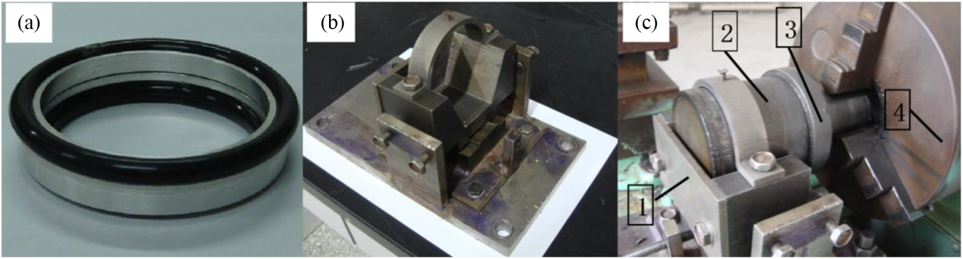
Wear test: (a) optimized seal, (b) holder, and (c) 1—holder, 2—cone, 3—shaft, and 4—chuck of the lathe.
Figure 20 demonstrates the average wear amount of the original metal rings and the optimized metal rings. The average wear of moving metal ring is greater than that of the static metal ring. The average wear amount of the optimized metal rings is less than 0.5 mg, while the average wear amount of the original moving metal rings is about 2.5 mg and the value for the static metal ring is about 1.3 mg. The wear mount of the optimized rings reduces to 20%–38% of the original structure. The wear amount of optimized metal rings drops sharply due to two reasons: (1) the frictional force decreases due to low contact pressure, reducing the amount of wear; (2) grease can effectively enter the sealing surface and play a good role in lubrication.

Average wear amount of the metal rings.
Conclusion
The failure of cone bit bearing seal was analyzed through experimental study and simulation analysis. Based on the analysis of failure mechanism, the structural optimization was proposed. According to the results analysis, the conclusions can be drawn as follows:
The damage of the rubber ring occurs on the shoulder, which is mainly due to high shear stress caused by large compression ratio. Serious wear appears on the sealing face of the metal rings because of unreasonable contact pressure distribution.
The dip angle, the width of the sealing face, and the back support structure were optimized. According to the analysis of contact pressure distribution and compression ratio, optimized structure parameters are as follows: the dip angle is 6°, the width of the sealing face is 3.4 mm, and the back supporting angle is 11°.
The performance of the optimized seal is significantly improved. The average compression ratio of the optimized seal rubber drops to less than 14%. The contact pressure distribution of the optimized seal is satisfactory that the mud and cuttings cannot enter the sealing face, but the grease can enter and act as lubricant. The wear mount of the new structure reduced to 20%–38% of the original structure.
In this article, the dip angles of the sealing face, the widths of the sealing face, and the back support structure were optimized one by one, and the interaction between parameters was not considered. The parameters of optimization may not be optimal, but this methodology improves the performance of the seal significantly and provides a reference for further study.
Footnotes
Handling Editor: Hiroshi Noguchi
Declaration of conflicting interests
The author(s) declared no potential conflicts of interest with respect to the research, authorship, and/or publication of this article.
Funding
The author(s) disclosed receipt of the following financial support for the research, authorship, and/or publication of this article: The authors wish to express their gratitude for the financial support by Jiangxi Feilong Rock Bits Manufacture Co., Ltd.