
Abstract
This article used a combined solution of ABAQUS and FE-SAFE to evaluate the performance and predict the fatigue life of the e-clip (a widely used e-clip in the railway system) under cyclic loading. With the proposed methods, the fatigue life analysis of the e-clip has been performed under 12 working conditions. The results show that the inside of the rear arch has the shortest fatigue life and it is therefore the most critical part, which is proved by the field observation. Another conclusion is that the insertion depth of the rear arch into the cast shoulder (short of the insertion depth) and the clip deflection are two of the most important parameters to the fatigue life. The mismatch of the two parameters may cause e-clip fractures. Finally, after optimization of the fatigue life analysis and energy analysis for the e-clip, it is suggested for the installation of e-clips that the clip deflection should be within 10–12 mm and the gap from rear arch to cast shoulder should be within 3–9 mm.
Introduction
Since the material fatigue failure exists widely in a variety of engineering structures, the method to mitigate the material fatigue damage as well to predict and extend the service life has been a focus issue in many technical researches. For railway track, the fastening system, as one of the most important components of track structure, is to provide flexibility for the track structure and to maintain a good track geometry, which is crucial for the stability and security of train operations. The fastening system with e-clip is widely used in railway system and urban transit system1–3 due to its advantages such as easy installation and removal, high elasticity, and good capability to adjust the gauge and track height.
In recent years, the e-clip fractures appear rather frequently in part of Beijing subway lines, which is so critical that has a direct impact on the operational safety of trains. The fatigue analysis of the fastening system has been conducted by many researchers. J Smutny 4 analyzed the dynamic behavior of the fastening system and studied the fatigue mechanism of fastening system in the frequency domain. X Zhao et al. 5 studied the response of fastening system under the dynamic wheel–rail contact forces in high frequency. JA Casado et al. 6 conducted the fatigue tests of the fastening system and proposed a model together with the suitable parameters which can identify the fatigue process. S Mohammadzadeh et al. 7 conducted the stress-based fatigue reliability analysis of the Vossloh spring clip type SKL14 under traffic loads. J Sadeghi et al. 8 studied the influences of train speed and axle loads on life cycle of rail fastening clips (Vossloh and Pandrol) and proposed that increases in axle loads cause substantial increases in the clip plastic deformations; train speeds have less influence on the deflection.
T Deshimaru et al. 9 proposed a method for predicting the fatigue life of rail clips by established the relationship between the applied loads and stress on the rail clip in laboratory tests. Z Yu et al. 10 studied the fatigue life and the critical position of the X2 e-clips, under the fatigue loading. S Zhu et al. 11 studied the Vossloh e-clips and concluded that the rail corrugation would accelerate the fatigue failure of the e-clips. Z Yan 12 claimed that the coarse and inhomogeneous material in the e-clips is the main reason of the reduction in the fatigue life. W Wang et al. 13 concluded that main reason of the fracture of the e-clips is the local stress concentration under the alternating stress. In addition, the fatigue cracks caused by the poor surface condition are also one of the important reasons of the fatigue failure. J Zhang 14 performed the fatigue test on the ω-clips; he found that the ω-clips fractured after three million times load cycles, and other scholars also studied the mechanism of fracture. 15 As can be seen from the above study, most researches of the fastening system fatigue are focused on the details such as the material properties, processing technology, and the loading conditions. However, the theoretical analysis is less focused, with the problems such as the models are over simplified, the boundary conditions are unreasonable, and it is incapable to achieve a quantitative prediction of the service life of the fastening system. Especially, a method for calculation and analysis that can be widely used has not yet been developed. As a result, it is still difficult to evaluate the fatigue performance of the e-clip under actual operating conditions and, moreover, to accurately estimate the fatigue life of each part of the e-clip.
With the development of technology, a variety of fatigue analysis simulation technologies have been used in the field of aircraft, cars, cranes, asphalt, and other metallic or non-metallic materials16–23; the popular software includes the following: FE-SAFE, HyperWorks, MSC Fatigue, ANSYS, and ABAQUS (XFEM). For example, Ç Altınok, 24 L Zou and T Center, 25 and HO Alil 26 have used ABAQUS and FE-SAFE to analyze metal fatigue. S Wang et al. 27 have used this method in highway pavement reflection crack analysis and nonmetal fatigue life analysis.
The fracture of the e-clips, under the long-term train load, is a typical metal fatigue failure, but at the same time, the fatigue damage of the fastener is different from that of conventional metal fatigue. The main reason is that the fastener is not only under the dynamic load of constant pressure, bending, shear, torsion, and other complex changes but also under the train axle load, speed, and other changes in the different fatigue responses. Based on this consideration, the FE-SAFE WORKS is a fatigue analysis software which has interfaces with many finite element software and post-processors. FE-SAFE module uses the advanced single biaxial fatigue calculation method, which allows to calculate the elastic or elastoplastic load history. 28 Hence, the software is used to perform fatigue analysis of the e-clip in this study. Besides, the software ABAQUS has been used to model the fastening system, with the consideration that the two solver modules (Standard and Explicit) are good at solving the complex nonlinear problems and the post-processor is user-friendly. In summary, the main purpose of this article is to try to adopt a new analysis method which combines the calculation of ABAQUS and FE-SAFE to study the fatigue failure of the fastening system in the subway. Furthermore, this method can be used to predict the life of Metro fasteners in Beijing and provides an effective means for the analysis of similar problems.
The simulation of the e-clip
Material properties
To ensure the accuracy of the calculation, the material properties in the fastening systems model are defined according to the factory index.
E-clip
E-clip is made by 60Si2Mn steel, and the material properties are shown in Table 1.
The material properties of the fastening clip.

As the clamping force increases, the e-clip yields plastic deformation. The theoretical elastic model is therefore not able to simulate the actual stress state of the e-clip. This study takes the plastic material property into consideration and conducts the nonlinear analysis to prevent that. The material property of the e-clip used in the simulation adopts the theoretical elastoplastic model, which is based on the material characteristics and the processing technology and also combined the elastoplastic model in ABAQUS. A feature of the material is that after the material reaches the yield strength, the stress continues to increase, but with a strengthening elastic modulus. According to Chinese national standard, GB/T1222-2007 spring steel, 29 the yield strength of the e-clip is 1200 MPa, the ultimate strength is 1300 MPa, and the strengthening elastic modulus E1 = 0.1E, as shown in Figure 1.

The theoretical elastoplastic model.
In Figure 1, line OA indicates the elastic stage of the material, while line AB represents the material in the linear strain-hardening elastic–plastic process. 30 The stress–strain relationship is as follows

Cast shoulder
Cast shoulder is exposed to the vertical pressure and therefore the frictional force from thee-clip and its stiffness is high. The cast shoulders of fastening system using e-clip are made by QT450-10 ductile iron. The material properties are shown in Table 2.
The material properties of the cast shoulder.

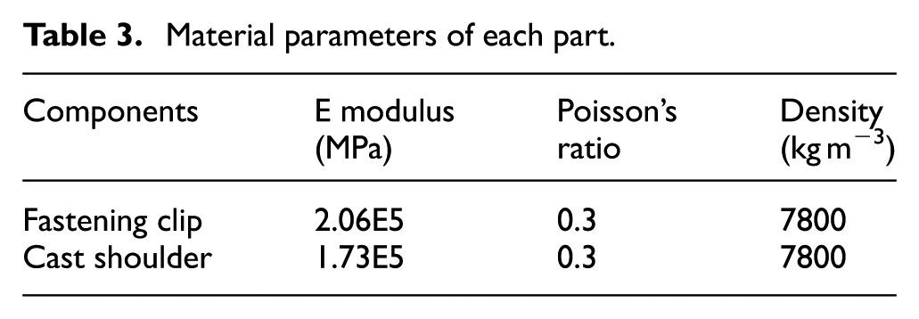
In summary, the material properties of the e-clip systems used in the fatigue analysis model are shown in Table 3.
Material parameters of each part.
The FE model
An e-clip is shown in Figure 2. In order to calculate fatigue behavior of the fastening clip precisely, the e-clip is modeled in strict accordance with its actual size. The fastening clip model is based on automatic meshing convergence; because of the complex spatial structure of the e-clip, the mesh of the e-clip is treated specially during calculation. When dealing with a regular structure, hexahedral meshing is more accurate than tetrahedral meshing. When dealing with a complex model, hexahedral mesh generation accounts for most of the model development time due to geometric complexity. Tetrahedral meshing, which can be more easily automated, has been the approach of choice to date in complex model. 31 In this article, the cross section between the clip toe and the front arch is meshed as tetrahedron elements (C3D4); the twist section between the front arch and the clip heel is meshed as wedge element (C3D6); while the rest are meshed as hexahedral elements (C3D8R). The model has in total 38,441 nodes and 33,864 elements. The cast shoulder is meshed as hexahedral elements and wedge elements, which are 18,409 nodes and 15,360 elements in total including 15,160 hexahedral elements (C3D8R) and 200 wedge elements (C3D6). After many times of calculation, the whole fastening clip is constructed by mesh size 2 mm; a further increase in mesh density did not change the output variables. The ultimate model of the e-clip is shown in Figure 3 and the mesh data for Figure 3 are shown in Table 4.

An e-clip fastening system used in the subway.

The model of the e-clip fastening system.
The mesh model data.

The contact definitions
To simulate the actual stress state, the contact between the e-clip and the cast shoulder adopts the nonlinear contact theory. To be more specific, the normal contact adopts the “hard contact” in ABAQUS, while the tangential contact adopts the Coulomb friction model, with the introduction of a penalty friction formula, which allows the “elastic slippage” as shown as dotted lines in Figure 4. The “elastic slippage” means a relatively small amount of movement that occurs between the contact surfaces. When it occurs, ABAQUS can automatically select the penalty stiffness (the slope of the dot lines). By such contact settlings, the discontinuity caused by the bonding and the slip in the fastening system can be solved.

The friction behavior.
The boundary condition under the cast shoulder of the fastening system model adopts the nonlinear Cartesian spring instead of the rigid constraints, which is to properly simulate damping behavior of the rail pads.
Combined solution of ABAQUS and FE-SAFE
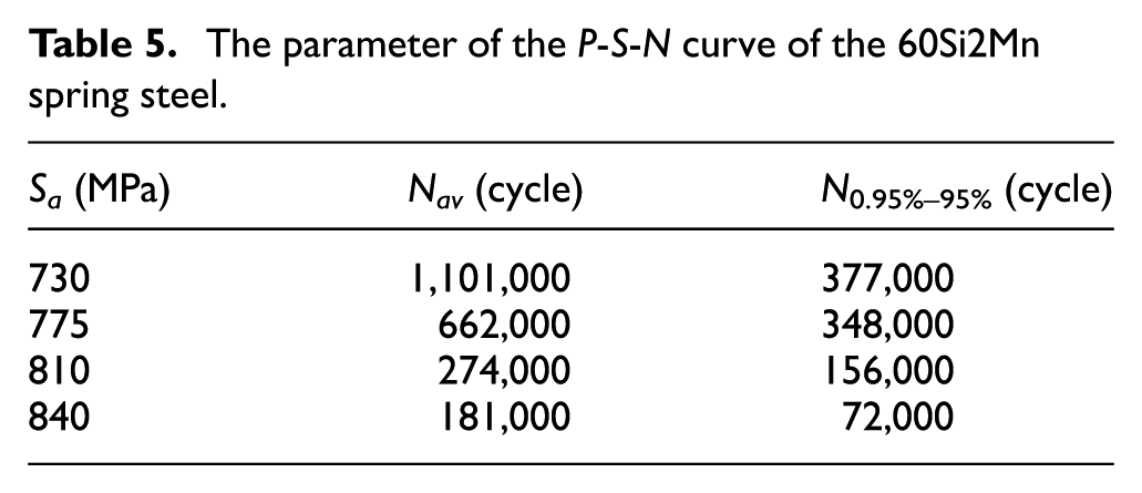
The P-S-N curve of the smooth bar which is of 7.5 mm diameter, made of the 60Si2Mn spring steel under four-level strength, which has the survival rate at 95%, 32 is shown in Table 5.
The parameter of the P-S-N curve of the 60Si2Mn spring steel.
Equations (2) and (3) are the regression based on parameters given in Table 5


According to Basquin S-N equation, the P-S-N curve is reconstructed when N obeys the logarithmic normal distribution. The reconstructed P-C-S-N curve is shown in equations (4)–(7), while the parameters of the reconstructed S-N curve are shown in Table 6


where


where N is the fatigue life and Sa is the fatigue strength;
The parameters of the reconstructed S-N of the 60Si2Mn spring steel.

The parameters of the fatigue analysis of the e-clips fastening system can be achieved by fitting the 95% survival rate S-N curve to the fatigue model of e-clip in FE-SAFE. The elastic yield strength is 1200 MPa, the design fatigue life is five million, and the axle load of the subway vehicle is 14 t. The stress ratio of the cyclic loading can therefore be obtained based on the stress extreme of the e-clip calculated by ABAQUS. Later, the load spectrum can be made in FE-SAFE.
In engineering field, the fatigue life of components depends not only on the stress amplitude but also on the initial stress state. Prior to the vehicle loads, the e-clip undergoes relative high initial stress caused by buckle pressure during the installation process. Hence, it is not enough to only consider changes in stress amplitude when calculating the fatigue life. The mean stress should be therefore modified. The common ultimate fatigue stress models 33 for mean stress are shown in Table 7 and Figure 5.
Fatigue limit stress models.


Fatigue limit stress models.
In Table 7,
As can be seen from Table 7, the expressions of Goodman model and Morrow model are simple, which are often applied in engineering, but the results are relatively conservative; the results of Gerber model and Cepeheeh model are close to the experiment data, but the former has a complicated expression and the latter needs to first get the fatigue limit
ABAQUS, as a re-processing and post-processing visualization software, inputs first the calculation results file (odb file) of the various conditions to FE-SAFE for the calculation of the fatigue life. Then, it inputs the prediction results to the ABAQUS for visualization after which the distribution of the fatigue life can be seen. The analysis process is shown in Figure 6.

The process of the fatigue analysis of the fastening system.
Case study
Case conditions
According to the operational characteristics of the subway lines, the fatigue analysis of the e-clip considers the vertical vibration load caused by the moving of the trains and the resonant of the e-clip caused by the rail corrugation. The fatigue loads are applied to clip toe and the amplitudes of the displacements are applied according to the test results, as shown in Figure 7 and Table 8. As proved by experiments, the two main factors that affect the performance of the e-clips are the insertion depth of the e-clips and the clip deflection of the e-clips. Under the train load, the most unfavorable conditions are used; the vertical displacement of the clip toe is 0.52 and −1.47 mm. The fatigue life of e-clip with the different installation states, in total, 12 cases, is therefore calculated as shown in Table 9.

Vertical displacement measurement of the clip toe.
Statistics of the vertical displacements at the clip toe (mm).

Cases of the fatigue analysis (mm).

The static model of the e-clips in ABAQUS is shown in Figure 8. As can be seen, the most unfavorable positions are the inside of the rear arch and the connection between the front arch and the toe part. For all the cases, five typical elements are therefore selected at each position to calculate the fatigue life and then predict the fatigue life of the e-clip.

The critical positions of the fastening clip.
Results analysis
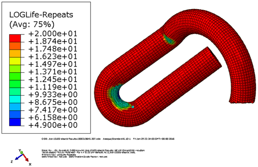
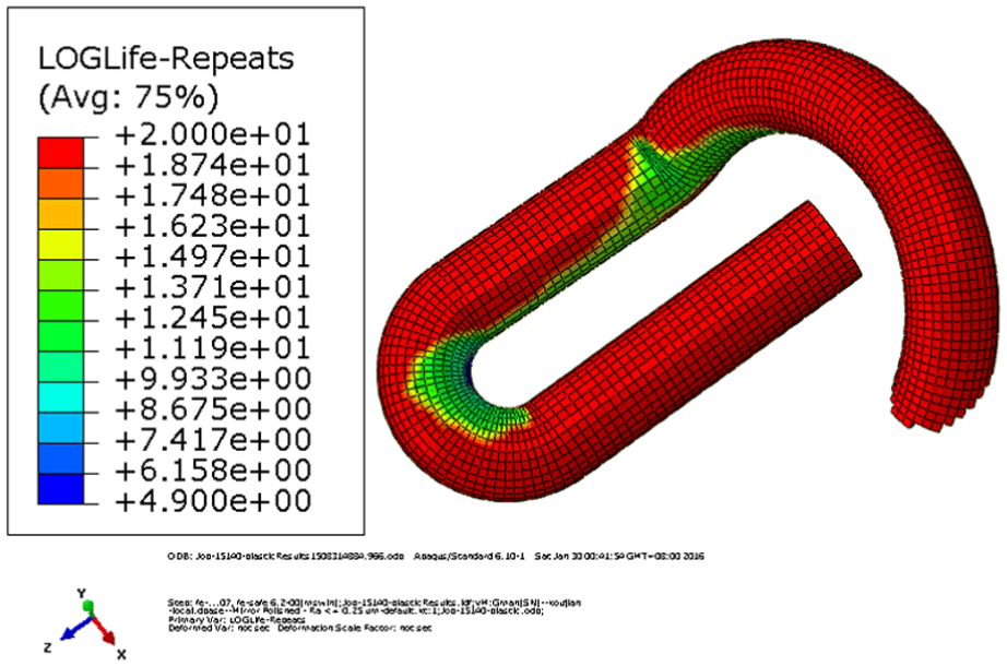
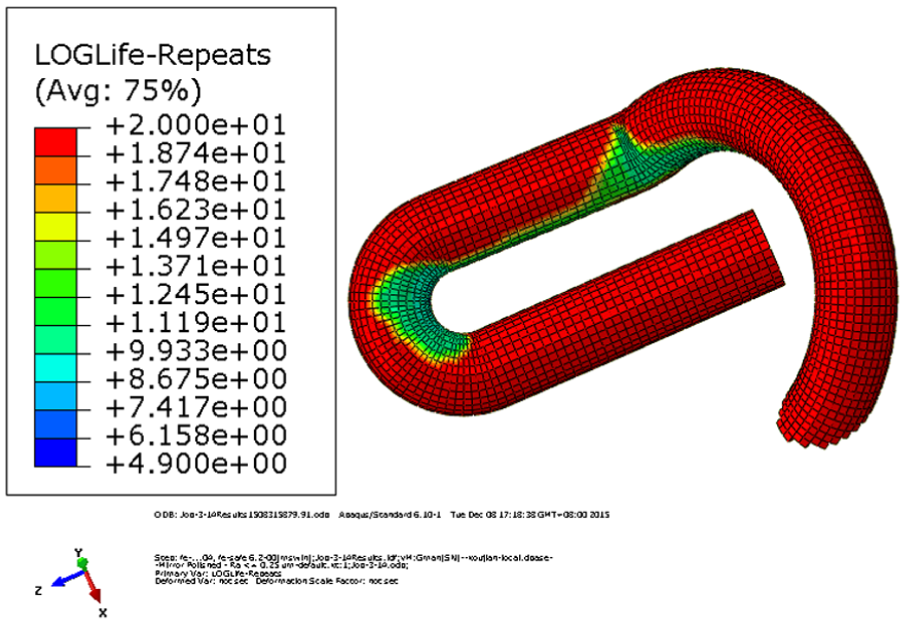
The distribution of the fatigue life of the e-clip in the typical cases is shown in Figures 9–17, and the detailed results are shown in Table 10. Note that the fatigue life is the logarithmic value, namely,
The distribution of fatigue life of case 1.
The distribution of fatigue life of case 3.

The distribution of fatigue life of case 4.
The distribution of fatigue life of case 6.

The distribution of fatigue life of case 7.

The distribution of fatigue life of case 9.

The distribution of fatigue life of case 10.

The distribution of fatigue life of case 12.
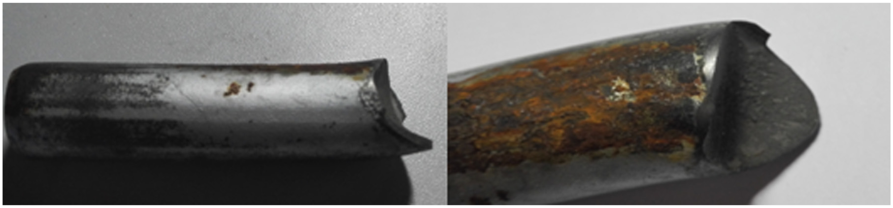
The fracture of the fastening clip (fracture at the rear arch).
The calculated fatigue life of all cases (1).

In the distribution of the fatigue life, the blue zones are the dangerous positions, while the red zones are the safe zones. As shown in Figures 9–16, the rear arch is the most critical cross section, which is in accordance with the fracture position of the e-clip found in the track, as shown in Figure 17. Therefore, the method is proved to be effective.
The effect of the gap from rear arch to cast shoulder and the clip deflection to the fatigue life is shown in Figure 18. It shows that the dangerous zone is increased when the clip deflection increases and the gap from rear arch to cast shoulder increases and the fatigue life is therefore reduced. The fatigue life of the e-clip is the shortest when the clip deflection is 14 mm and the gap from rear arch to cast shoulder is 1.5 mm.

The effect of the insertion depth and the clip deflection to the fatigue life.
Some conclusions can be found from the above analysis:
In all cases, the fatigue life of the inside of the rear arch is the shortest, and the rear arch is therefore the most dangerous position. The second dangerous position is the connection between the front arch and the clip toe, which also has stress concentration. In addition, the results show that when the insertion depth remains constant, the clip deflection is increased from 10.5 to 14 mm, and the fatigue life is reduced exponentially.
When the gap from rear arch to cast shoulder is 1.5 mm, the fatigue life in all cases is less than five million times, which is the expected service life, wherein even the highest fatigue life is 1,729,800 times. All cases do not meet the requirements of the fastener service life. Especially, when the clip deflection is 14 mm, the fatigue life is only 84,600 times, which is 1.7% of the expected service life. Field observations show that the departure interval of Beijing subways is about 3 min and the daily working period is about 17.5 h. The fatigue life of the e-clip in this case is, according to the fatigue analysis, supposed to be 84, 600/(17.5 . 60 . 30/3) = 8.05 months, which means after 8-month operation, the fracture of e-clip should start to appear. This is in accordance with the field observation that the many fractures of e-clips are found after 8-month operation. Again, the fatigue analysis is proved to be reasonable.
When the gap from rear arch to cast shoulder is 3 mm and clip deflection is 14 mm, the fatigue life of the e-clip is 3,233,000 times. The fatigue life of the e-clip is 1,767,000 times, which is less than expected service life.
The fatigue life of the cases with the gap from rear arch to cast shoulder is 6 and 8 mm, which are all higher the five million times. Besides, the fatigue life also decreases when the clip deflection increases.
The design optimization of the e-clip
The optimization based on the fatigue life analysis
The designs of the e-clip are optimized using the proposed fatigue analysis method. Besides, the five million times service life is also used as the criterion. The results are shown in Figure 19.

The fatigue life of fastening clip in all cases.
Figure 19 shows that when the gap from rear arch to cast shoulder is 1.5 mm, the fatigue lives of all e-clips are lower than the expected service life, and when the gap from rear arch to cast shoulder is 3 mm and the clip deflection is 14 mm, the fatigue life does not meet the requirement, either. It is therefore suggested that the gap from rear arch to cast shoulder should be more than 3 mm, while the clip deflection is less the 12 mm. In general, the insertion depth and the clip deflection should be combined carefully to prevent fracture of the e-clips.
The optimization based on the energy analysis
Besides meeting the requirements of the pressure, fatigue strength, and residual deformation, an e-clip is also evaluated for the ability to store energy, in other words, the more the energy can be stored per unit mass of the e-clip, the better the e-clips are.34,35 The energy W, stored by the unit mass of the e-clip after the same loading, is therefore used as a criterion for the design of the e-clip. The equation is shown as follows

where P is the clamping force (kN), Δ is the clip distance, m is mass of the e-clip (kg), and
If other requirements are satisfied, the more W is, the better the design of the fastening clip is. The mass of the e-clip is 0.64 kg. 28 Combining with the analysis results calculated by ABAQUS in the previous section, with the condition that the insertion depth is within3–9 mm and the clip distance is within 10–12 mm, it is found that the clamping force scales linearly with the clip deflection. The results of energy W are shown in Table 11 and Figure 20.
The energy W of all the cases.


The energy W of all the cases.
It can be seen from Table 11 and Figure 20 that the energy increases as the clip deflection increases and as the insertion depth decreases. When the gap from rear arch to cast shoulder is 3 mm and the clip deflection is 12 mm, the energy reaches its maximum, which is 30.2% higher than the normal condition. It is therefore suggested that the insertion depth should be increased, while the clip deflection should be decreased within the reasonable range.
Conclusion
With reference to other industry fatigue analysis methods, this article established an e-clip–refined model by ABAQUS. With the help of FE-SAFE, this article made a new attempt to analyze the fatigue fracture of e-clip. The calculation results have a good correlation with the field observation, which validates the analyzing method.
Analysis results show that the insertion depth and the clip deflection are the important parameters to the fatigue behavior of the e-clip. The mismatch of the two parameters may cause the fracture of the e-clip.
The e-clips are optimized by the fatigue life analysis and the energy analysis. The suggestions are that the clip deflection should be within 10–12 mm, and the gap from rear arch to cast shoulder should be within 3–9 mm.
Footnotes
Handling Editor: Ismet Baran
Declaration of conflicting interests
The author(s) declared no potential conflicts of interest with respect to the research, authorship, and/or publication of this article.
Funding
The author(s) disclosed receipt of the following financial support for the research, authorship, and/or publication of this article: The work was financially supported by the Fundamental Research Funds for the Central Universities (2015JBZ004).