
Abstract
Based on the characteristics of large tumbling space debris, this article proposes an effective method for whole-body compliant controller to eliminate the effects of the relative velocity between chaser and target which is not zero after the capture hands hold their corresponding handles tightly that is named as connection compliant phase. First, the kinematics and dynamics models are established, including tumbling target, free-floating chaser and chaser–target, respectively. Second, to analyse the characteristics of capturing of a large tumbling target, a simplified kinematics model about the centre of mass of the chaser is established, and a Cartesian-space compliant controller is designed in order to achieve the desired gross force as the input of multi-arm compliant distribution. Subsequently, we propose a method based on centre of forces to distribute the desired gross force to each arm optimized first and also a closed-loop regulator based on the dissipation vectors online as the second step. Then, a passivity-based control strategy is used in order to enhance the robustness of the system. Finally, the effectiveness of the control strategy mentioned above is verified by the simulation and air-bearing experiment in the horizontal plane partially.
Introduction
The increasing launch activities produce more and more debris on Earth’s orbits, which mainly includes failure satellites and rocket upstage bodies. The debris are floating freely on orbit, occupying valuable orbit resources and threatening other working spacecrafts. The debris with larger size and greater mass may cause more serious damages, such as rocket upstage and large satellite. The removal of debris has become a common responsibility and obligation of all mankind.
As is known, rocket launch is very expensive, so the lighter the payload, the lower the launch costs. Reducing the launch mass of space robot as a payload is a very important and challenging task. The payload limitation from rocket will inevitably affect the improvement of the function and performance of the space robot designed, such as more flexible and stronger propulsion flight capability and longer life. So how to design a more versatile, smaller and lighter space robot is of great significance for the robotic grasping and manipulation.
The ETS-IIV 1 from Japan, Orbital Express 2 from the United States and TECSAS/DEOS 3 from Europe are the typical capture of cooperative target. A lot of research work has been carried out on capturing and removing non-cooperative objects from their orbit.4–6 The debris removal by robotic manipulators seems to be the solution with the longest space experience. 7 The so-called large or small debris is generally connected with the size, mass and inertia of the space robot and the typical case about capturing of large non-cooperative target is the Phoenix 8 of DARPA in the United States, in which the mass of the target is about four times larger than that of the space robot. The focus of current research on robotic capturing is mainly on capturing of small target,9–14 that is, the size and mass of the target are smaller than those of the chaser. In such kind of capture process, the chaser oversees the relationship, and therefore the large target is in charge of the process of capture for the weight advantage.
Some debris are as large as cars or even buses. They tumble uncontrollably and move faster than a speeding bullet. So it is a challenging task for a small robot chaser to capture a large target. They need to have enough flexibility to ensure that the capture process does not cause damage to the chaser or target, and should not push the target away in case the capture failed. In addition, uncontrolled debris always keeps a tumbling state for residual angular momentum due to various mechanical failures or fuel depletion, which will deduce a huge challenge for capturing. Therefore, more attention should be paid on how to deal with the influence of tumbling debris. Quite few technical references in the literature can be found on autonomous capture of a large tumbling target and such manoeuvres have been attempted rarely.
Space robots, named chaser in this article, are generally composed of a satellite-like base and one or more arms mounted on the base and other functional units, for example, solar panel, boosters and object cognition sensors. The base is used for energy management, on-orbit flight control, communication with Earth and so on, while the arms are applied to grasping, manipulation and so on. An end-effector with a specific function is always fixed on the end of the arm, and the end-effector and the corresponding fixtures are named ‘hand’ and ‘handle’ in the following sections, respectively.
The process of capturing of large debris can be divided into three main phases,6,15 named pre-capture phase, capturing phase and post-capture phase. Based on the characteristics of large-scale tumbling debris, the capturing phase is divided into three substages: active detumbling phase (ADP), impact contact phase (ICP) and connection compliant phase (CCP). This article focuses on CCP and on the problem of compliant control after the capture hands hold their corresponding handles tightly but the relative velocity between the CoM of the chaser and that of the target is not zero.
The contribution of this article lies in the presentation of a whole-body compliant control method based on a multi-arm space robot. In addition, based on the modelling of kinematics and dynamics with constraints, a passivity-based compliant controller is designed to distribute the integrated output force from all hands of the chaser with reasonable principles online. We verify our work with a set of contrast simulations and an experiment on air-bearing bed. In particular, we demonstrate that our approach enables a space multi-arm robot to capture large tumbling debris safely by coping with external forces caused by tumbling of the target from the uncertain environment and make a whole-body compliant reactive behaviour.
This article is organized as follows. Section ‘Modelling target and chaser’ describes the kinematics and dynamics models of the chaser, target and the combined body. Based on the capture of uncertain large tumbling target, section ‘Whole-body compliance control’ designs an online regulator, which includes a distributor based on centre of forces (CoF) and a regulator based on dissipation vector, and designs a passivity-based controller to control the CoM of the chaser and distribute the external force to several arms reasonably. Section ‘Simulation and experiments’ shows the simulations and experiments based on air bearing and analyses the results. Finally, section ‘Conclusion and future work’ summarizes the conclusions from the chaser–target interaction perspective and proposes discussion of future work.
Modelling target and chaser
A challenging scene of a multi-arm chaser capturing a large target is shown in Figure 1. The mass of the chaser mentioned in this article is about 500 kg. The mass of the debris of the rocket upstage is generally 1.5 to 5 t, and the ratio of the target to the chaser is about 3:10, which belongs to the capturing of a large target. The research work in this article is based on the condition.
Chaser versus target.
Target
To enhance the ratio of output to input of the rocket launch, we choose the multi-satellite style for the modern rockets mostly. The upstage is the final stage of the rocket with several payloads, such as satellites or aerocraft, which are transported to the corresponding orbit one by one. After all these tasks, the upstage loses power and control, floats freely on orbit and then becomes debris.
As typical large debris, the rocket upstage shown in Figure 1 has the following characteristics: large-scale, large mass, generally cylindrical and always tumbling; therefore, it is difficult and dangerous to be captured. The upstage can be modelled as a cylinder. Assuming that there are enough handles on the one end of the cylinder that can be used to catch by the corresponding arms, such as the satellite–rocket docking ring, the focus of this article is on the scene that all the arms are involved in the capture and enough handles can be found.
Large debris has residual momentum before inevitable failure. In addition, after being impacted by other debris, it is possible for the debris to generate a larger tumbling velocity due to momentum exchange, which makes the spinning of the target more complicated.
The centre of mass (CoM) of the target is denoted as T-CoM;
Assuming that the object is axisymmetric and the mass is distributed evenly, the CoM of the target floats freely on Earth orbit with constant

where


where
In the process of motion,
The model of rocket upstage body.
From equation (1), the dynamics motion of the target with external force from handles can be described as

where

where m and
Generalized Jacobian matrix

Furthermore, the relationship of the generalized velocity of the

Then, the motion of the

The compact expression of all the handles is described using the following equation from equation (10)

where
Chaser
To cope with the mission of large tumbling debris and satisfy the need of multi-function manipulation of the space robot chaser, members in our laboratory designed a four-arm robotic chaser platform, hoping to carry out the following research work on the platform.
To reduce costs for multi-function space robot;
To make short-range manoeuvrability flexible on orbit;
To realize safety of capturing of large tumbling debris;
To carry out multi-arm work and enhance the complex operational capacity, such as the replacement of the functional unit.
The robotic system, named as Active Debris Removal Cleaner (ADRC), is shown in Figure 3.
The model of the chaser with four arms and combined body.
The chaser shown in Figure 3 contains a base and four same arms with six degrees of freedom (DoFs) which is described in Liu et al.
16
The chaser floats on the orbit freely according to the reference coordinates
Without losing generality, the number of arms of the chaser is denoted as N and the
According to ADRC, the number of arms mounted on the body is
As shown in Figure 4, the base of the target is denoted as the

Model of the chaser that is in contact with the target.
The location vector


The CoM of the chaser including all rigid bodies satisfies the following equations


Solving equations (14) and (15), we can obtain the vector expression of the CoM of the chaser as

where
Deriving the expression of the

where

where
The time derivative of equation (18) leads to

Now, the kinematic expression of all the hands can be described by the motion of the base and all joints in equations (18) and (19).
Combined chaser–target
Different from single-arm robot, a multi-arm chaser constructs several kinematic closed-loop chains for the cooperative operation, that is, the kinematic and force closed chain should be solved.
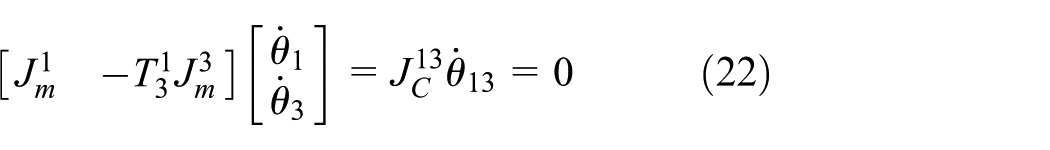
The topology of the chaser from the open tree chain in Figure 3 to closed-loop one when all arms of the chaser connect with corresponding handles on the target. The motion of the arms will be strictly constrained for the kinematic closed-loop configuration as shown in Figure 5. Obviously, all the four arms of ADRC compose three independent kinematic closed-loop chains, set as Arm-1 with Arm-2, Arm-1 with Arm-3 and Arm-1 with Arm-4, respectively. The kinematic constraints in the sense of velocity can be written as
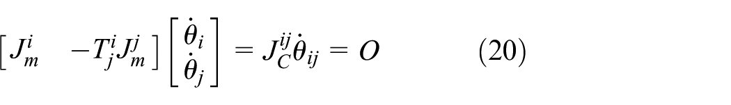
where
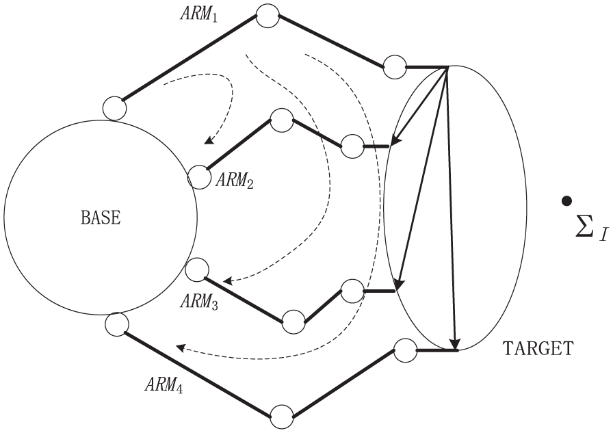
Three independent constraint closed loops.
Therefore, the three independent constraint equations of ADRC in Figure 5 can be described using equation (20) as follows

Similarly, we know

In conclusion, the kinematic constraint equation of the chaser–target can be described as

where
Then, the constraints from the motion of the base are introduced. The kinematic constraints of multi-arm grasping the same target have nothing to do with the motion of the base. Then the constraint equation can be rewritten as

where
Dynamics modelling
Using the generalized coordinates

where
Time-based differentiation is performed for equation (25) yielding the following equation

One of the important control issues mentioned in this article is base control. Therefore, it is convenient to address the CoM of the chaser to consider.
The simple linear dynamics of CoM of the chaser is described as

Therefore, we can control
Solving equations (27) and (28) for q yields

Therefore, we can calculate the corresponding joint torque by inverting equation (29) for the desired
Summary
The mathematical models for the problem of multi-arm chaser capturing a large target are established in this section, and the basic assumptions to solve the problem are proposed. Section ‘Target’ establishes the kinematics and dynamics models for large debris capture. To cope with the diversified mission on orbit, section ‘Chaser’ designs a space robot chaser, and the theory of multi-body rigid is used to model the multi-arm chaser. When the chaser and the target contact with each other, the motion of capture arms follows the strict kinematic constraints, which constitutes several kinematics closed-loop chains. Section ‘Combined chaser–target’ describes the constraints in detail. Finally, section ‘Dynamics modelling’ describes the dynamics model of the chaser in the role of the external force from the hands and the relationship between the gross force and accelerator of the CoM of the chaser.
Whole-body compliance control
As mentioned above, the initial angular momentum of the target is transmitted to the base via the arms to drive the combined body moving after the chaser combined with the target. If the chaser is not driven by the thrusters, that is,
Gross force control
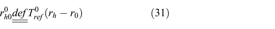
At the beginning of the compliant process, the initial generalized relative position of a hand according to the base is defined as

where
Based on the same rules as in equation (30), the current generalized relative position is denoted as
The desired acceleration

where
Substituting equation (32) into equation (28), we get the desired gross force

As the desired integrated control goal, the gross force
Force compliant distribution
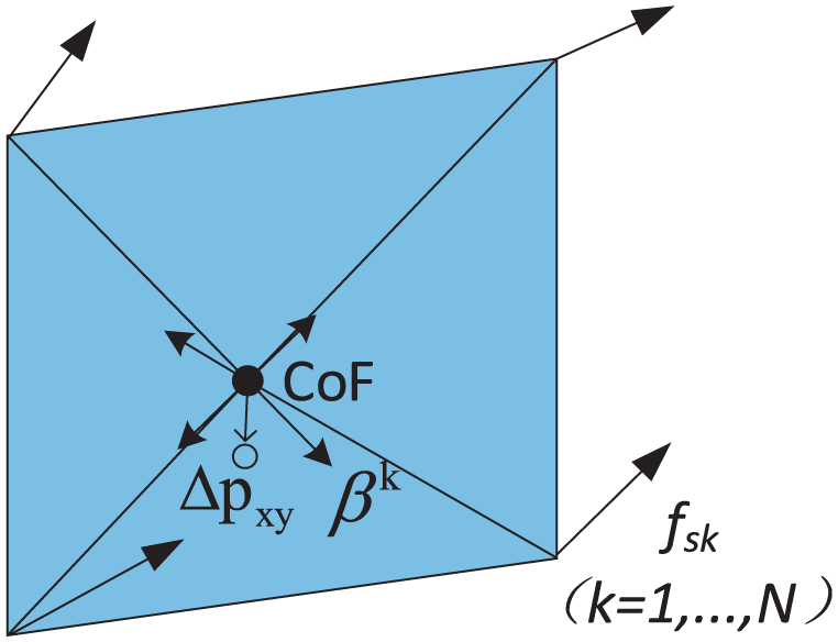
This section describes a force distribution strategy based on the CoF, which describes the weight of the multi-arm force distribution. Some research work has been done on this method.19,20
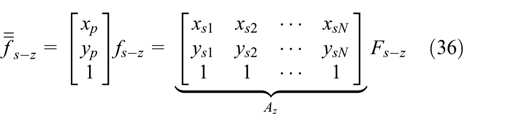
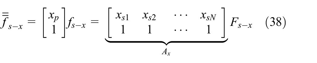
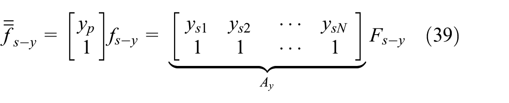
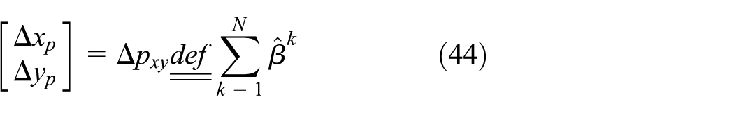
The CoF of the arms of the chaser can be expressed as


where

Equations (33), (34) and (35) can be combined into simple notation as
Given a desired normal gross force

where

Similar to the above method, the following equations can be deduced
Therefore, a desired gross force might be distributed over all the desired contact points using a combined matrix style

where
The joint which provides the maximum torque can be denoted as

where
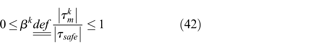
where

where
Yield refined desired CoF as

Dissipation vector regulator online.
Being regulated by CoF- and dissipation-vector-based regulator online, the process of the chaser capturing the target shows better flexibility and the payload force of all the joints are distributed in whole-body optimization.
Then we get the renewed distribution matrix as

And the new mapping relationship between the gross force on the chaser and the distributed force on multiple contact points of the hands can be expressed as

where
Passivity-based control frame
To realize globally, exact tracking should be performed in independent coordination. Inverse dynamics control is more demanding on model accuracy, but it is difficult to achieve in engineering. Lyapunov-based control has been successfully applied to robotic system. 21 The method does not seek linearization or decoupling, but only asymptotic convergence of the tracking error. As an alternative algorithm to Lyapunov-based control schemes, passivity-based control22,23 scheme can be designed which explicitly exploits the passivity properties of the Lagrange model. The algorithm is expected to have better robustness properties compared with the inverse dynamics method, because it does not rely on the exact cancellation of the non-linearities of a multi-rigid body robotic system.
The motion relationship of the tips of the hands and the base of the chaser is given by

where

The desired generalized variables

The error of generalized variables is

Design the following transform from equation (26)


where
In consideration of the properties of the multi-arm chaser, the choice of

So we know

The composition of the control input joint drive torque takes into account the multi-point contact force that are reasonably distributed and the system’s passivity-based characteristics, and the system has been translated into a first-order system from a second-order one. The calculation process and the proof of stability in the sense of Lyapunov are detailed in Appendix 1. Then, we get the controller based on passivity properties.
Summary
This section presents a whole-body active compliant control strategy of a multi-arm chaser, which greatly enhances the security of the chaser capturing a large tumbling target and effectively avoids the inertia force supplied on the rotation joints of the arms that may cause overload damage. Section ‘Gross force control’ establishes the models from the perspective of the chaser and combined body, and the motion relation of the multi-rigid body system is obtained. Section ‘Force compliant distribution’ proposes a multi-arm force distribution method with the desired driving force. The CoF distribution method is used to construct a simple and effective force distribution matrix, so that the arm can distribute the external force reasonably and improve the survivability of the chaser as much as possible as the preliminary first step. In addition, an online regulator based on dissipation vectors is proposed and the compliant process is further optimized on the basis of the above force distribution. Section ‘Passivity-based control frame’ proposes a passivity-based controller, which is insensitive to the model parameters compared with the model-based control method. And then the stability in the sense of Lyapunov is proved.
Simulation and experiments
Simulation
A four-arm chaser named ADRC is taken as a practical application to verify the proposed strategy and the auxiliary simulator is V-REP. 24
In order to verify the effect of the compliant controller, a set of simulations are carried out with and without the compliant controller, respectively. The excitation force
Some chaser parameters are as follows. The four arms mounted on the base are the same as the others. The 6-DoF arm was designed in our lab, the mathematical model of the arm is shown in Figure 7, and the Denavit–Hartenberg parameters are shown in Table 1.
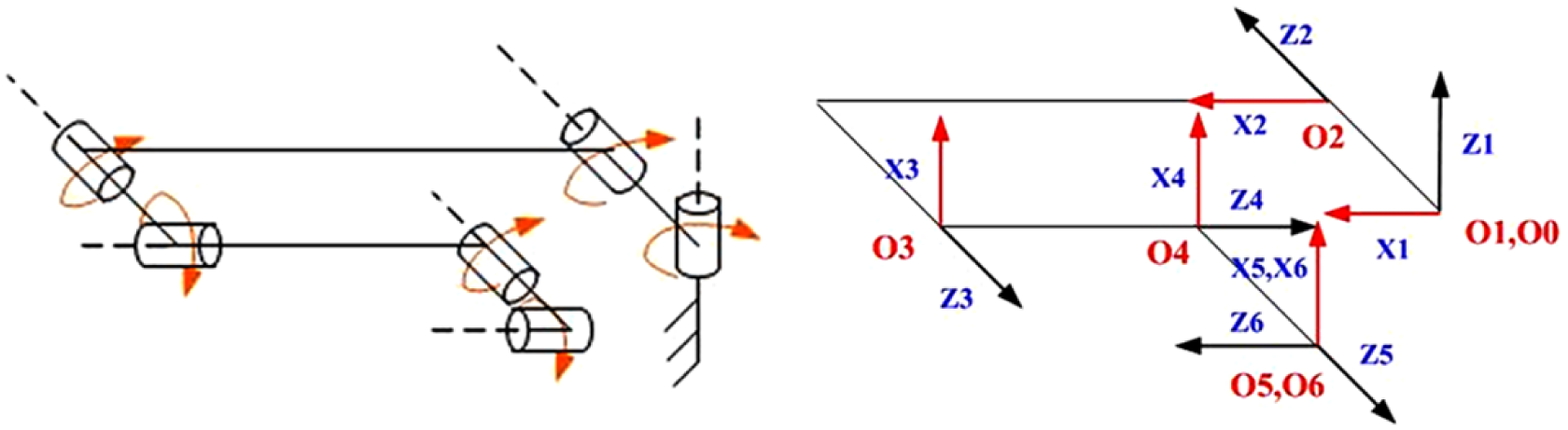
Manipulator kinematics modelling.
Denavit–Hartenberg parameters.

Here,
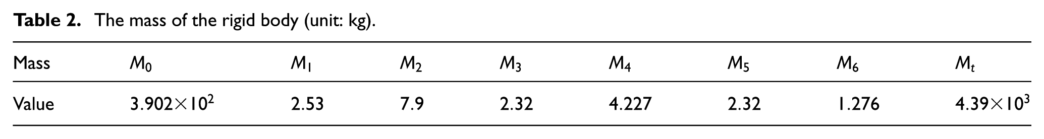
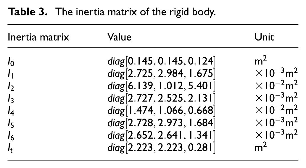
The mass and the inertial matrix of the
The mass of the rigid body (unit: kg).
The inertia matrix of the rigid body.
Four arms of the chaser connect the corresponding handles separately and remain in the initial configuration. A transient drive torque is applied to the CoM of the target to simulate the effect from the tumbling target to the arms of the chaser to ensure that the compliant controller is effective when the chaser is disturbed by the target. The validity of the strategy is verified by comparing the cases with and without a compliant controller. The initial parameters of the contrast experiment are given as follows.
The constant torque supplied to the CoM of the target for simulation is
The initial configuration of the
where the units of the position and angle are metre and degree in this article. The initial parameters of the target are
The wrist force and moment curves of the arms with and without compliant controller are shown in Figures 8, 10, 12 and 14, and the joint torque curves of the arms with and without compliant controller are shown in Figures 9, 11, 13 and 15, respectively. In the comparison of the curves with compliant controller (red dashed line) and those without compliant controller just holding the configuration of all the arms (blue solid line), the joint torque peak of the arms with compliant controller is significantly smaller and softer than that of the arms without compliant controller. The force of waist and the torque of joint cyclical change with the sine-like wave for the position hold control in the process of momentum exchange. Furthermore, the chaser regulates the force actively to weaken the inertia force from the mass of both ends of the arms based on joint active motion. So the compliant strategy is verified to be effective in the simulation.
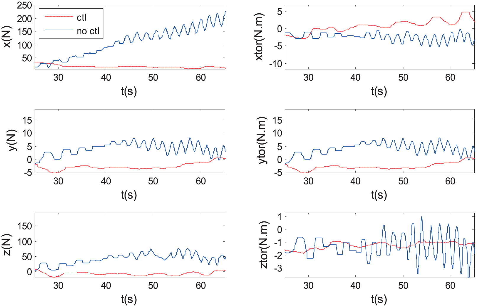
The wrist force and moment of Arm-1.
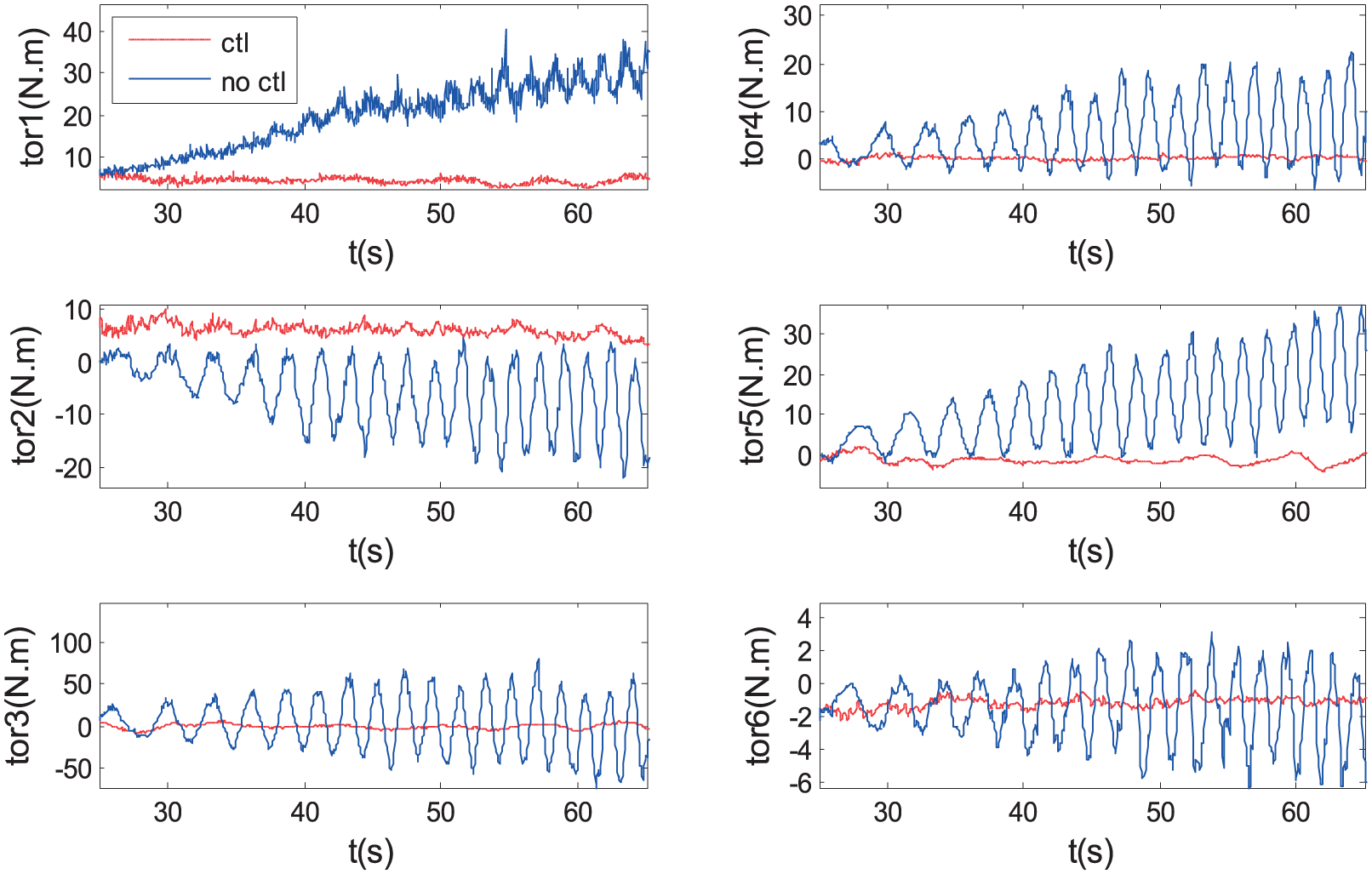
The joint torque of Arm-1.

The wrist force and moment of Arm-2.

The joint torque of Arm-2.

The wrist force and moment of Arm-3.

The joint torque of Arm-3.

The wrist force and moment of Arm-4.

The joint torque of Arm-4.
The CoM trajectories of the base of the chaser, of the target and of one hand of the chaser are shown in Figure 16, and the wrist force curves of the four arms are shown in Figures 8, 10, 12 and 14, respectively. Four arms are of similar force from the external environment for the distribution strategy. From the curves shown in Figure 16, it can be seen that the motion process is in charge of the target for its large mass and the chaser follows the motion of the target to reduce the force of the arms. Obviously, the larger target is in charge of the combined process.

The trajectory curves of the target, hand and chaser.
As shown in Figures 17 and 19, the projection curves of CoF on the handle’s plane (as shown in Figure 2) are controlled by the CoF-based force distribution controller and dissipative-vector-based regulator. In order to verify the effectiveness of the force regulator online, the projection of CoF in the z-direction is recorded and analysed as shown in Figure 17. The projection curves in the plane show that the control of the force distribution regulator can converge and stabilize quickly after being impacted by external disturbance (Figure 18).
CoF projection on the x-axis of the x–y plane.

CoF projection on the y-axis of the x–y plane.
The projection of CoF on the x–y plane is shown in Figure 19, which verifies that the distribution strategy is useful. The project point sets of CoF on the x–y plane are distributed as shown in Figure 19, and the CoF is regulated online based on the strategy mentioned above.

CoF projection on the x–y plane.
Ground experiment based on air bearing
The complete experiment with a whole 4-arm chaser capturing the target is almost impossible to carry out due to the difference in the gravity environment between the orbit and the ground. So the ground experiment needs to be designed equivalently, and the algorithm can be verified partially or just in one point. As shown in Figure 20, the experimental platform based on air-bearing technology was developed in our lab, which consists of a base and two 6-DoF arms, but only 3 DoFs of each arm in the horizontal plane can be experimented. The base of the chaser contains a battery, controller, high-pressure air cylinders and other equipment. The parameters of the two arms are the same as those mentioned in the previous sections. The arm is equipped with a one-dimensional embedded torque sensor in every joint,16,25 and the joint controller can sense the joint torque and give feedback of the data to the upper controller through the field bus for force control. The gravity of the arms and base is compensated by several distributed air feet, and the approximate microgravity environment is built in the horizontal plane.25,26

Site photos of ground experiment of the dual-arm platform.
To verify the effectiveness of the compliant controller in response to the external disturbance, the following experiment was designed: the two hands of the robot held by a fixed object (railing in Figure 21), forming a closed-loop chain, and an external force supplied by experimenter on the base to examine the joint torque and the compliant behaviour. The results can verify the effectiveness of the control strategy in the horizontal plane partially.

The slides of the experiment based on air bearing.
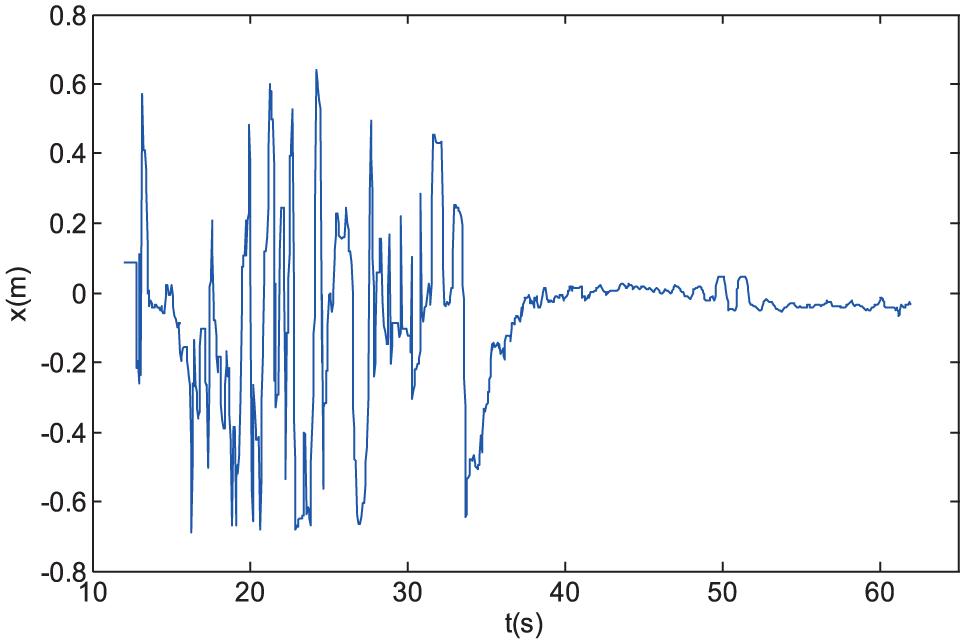
As shown in Figure 21, when the experimenter pushes the base of the two-arm chaser on air bearing in the horizontal plane which was constructed into a microgravity environment with air bearing, the compliant controller exhibits a reactive behaviour and unloads the external force disturbance supplied to the chaser, thereby reducing the effect on the arm joint from the external force (Figure 22). The joint position curves with compliant control are shown in Figure 23, and the corresponding velocity curves are shown in Figure 24. The figures just show the curves of joint2, joint3 and joint5 which are the horizontal motion DoFs of the arm of ADRC for the constraint of air bearing. The constraints of motion do not affect the verification of compliant control algorithms. These pictures are sampled every 3 s from a video.

Joint torque curves of the dual-arm experiment.

Joint position curves of the dual-arm experiment.

Joint velocity curves of the dual-arm experiment.
From the curves of the motion and joint force of the two arms, it can be seen that when the base of the chaser is supplied an external force, the two arms will unload the effects of the external force to achieve compliant behaviour.
Conclusion and future work
In this article, we presented our motivation and challenge for the study of multi-arm robotic capturing of large tumbling target and conduct safety capture research for large tumbling debris such as large rocket upstage. Through the mathematical modelling of the chaser, target and chaser–target, the control strategy of capturing safety with uncertain dynamics parameters is studied. The main contributions of this article are as follows:
The kinematics and dynamics models of the chaser and target are modelled and the constraint conditions of the closed loop from four capture arms are established, and a whole-body control strategy based on the Cartesian-space impedance behaviour is designed.
We propose a multi-arm force distribution method that consists of a CoF distributor and a dissipation vector regulator, so that the output force from the hands of the chaser can be distributed to multiple arms reasonably.
A passivity-based controller is designed to further improve the performance of the system and the stability is proven in the sense of Lyapunov.
The compliant control strategy is verified by simulations and experiments based on air bearing. 26 The phenomenon of non-synchronization between the arms and its possible impact on the capture safety is not considered in this article, and the multi-arm successive contact phenomenon to the challenge of the chaser’s whole-body compliant control behaviour will be taken into consideration in the future research. In addition, we will further enhance the chaser in the face of unknown environmental models and look forward to apply more technology on-orbit.
Footnotes
Appendix 1
The process of the error function calculation and the stability proof in the sense of Lyapunov are detailed in the following.
The system dynamics can be expressed as
And the control law
Substituting equations (52) and (53) into equation (58), we get the following expression
Substituting equation (59) into equation (57), the system error dynamics equation can be expressed as
This equation can be simplified using equations (53) and (55)
where
Then, consider the following Lyapunov function
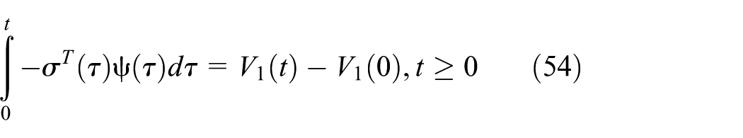
The passivity properties of the mapping from
In view of the passivity of the mapping from
Acknowledgements
The authors would like to acknowledge the support of the team members for their outstanding contributions to this article and also thank the reviewers for their helpful comments and suggestions.
Handling Editor: Jose Antonio Tenreiro Machado
Declaration of conflicting interests
The author(s) declared no potential conflicts of interest with respect to the research, authorship and/or publication of this article.
Funding
The author(s) disclosed receipt of the following financial support for the research, authorship and/or publication of this article: The research work was supported in part by the government of China, and some basic work was supported in part by the National Natural Science Foundation of China under Grant Nos 61320106012, 61533004 and 61703043.