
Abstract
Magnetic bearings have been used in flywheel energy storage systems to improve their performance because these kinds of bearings can provide non-contact supporting so that the friction between the rotor and the bearings is reduced significantly. However, the gyroscopic coupling, parameter coupling, and imbalance force affect the operating performance and stability of a magnetic suspended flywheel energy storage system with asymmetric rotor; therefore, the main purpose of this study is to propose a control method for achieving decoupling and stable operation of the aforementioned system. To this end, after deriving the mathematical model of a radial 4-degree-of-freedom rotor–bearing system, a novel cross-feedback-based modal decoupling controller is designed for vibration suppression caused by gyroscopic coupling, parameter coupling, and imbalance force. Better performance is obtained through comparing the decoupling performance, control performance, and disturbance rejection performance with a traditional decentralized proportional–integral–derivative controller and a cross-feedback controller via ADAMS–MATLAB co-simulation technology and experimental results.
Keywords
Introduction
Flywheel energy storage systems which are also called flywheel battery have been used more and more for energy harvesting and recycling in many situations, such as space satellites, renewable energy power generation systems, and electric vehicles, because of their cleanliness and high-density energy storage. Their capacity of energy storage almost depends on the rotor velocity; however, the traditional flywheel energy storage systems have significant friction between the rotor and the bearings. Hence, recently the applications of flywheel energy storage technologies are limited.
Magnetic bearings have been used in flywheel energy storage systems to improve their performance because these kinds of bearings can provide non-contact supporting. As the rotation is frictionless, there is no wear and no lubrication requirement, and very high rotation speeds are possible. 1 However, the gyroscopic coupling, parameter coupling, and imbalance force could cause rotor vibration so that the operating performance and stability of flywheel energy storage systems could be degraded. Hence, the main purpose of this study is to propose a control method for achieving decoupling and stable operation of the aforementioned system.
To this end, various control schemes have been presented. These methods can be classified into two types: decentralized control, which is a combination of several single-degree-of-freedom (DOF) controllers,2–5 and centralized control, which is a multiple DOF controller.6–10 Chen et al. presented a decentralized proportional–integral–derivative neural network (PIDNN) control scheme for regulating and stabilizing a 5-DOF active magnetic bearing (AMB). Good control performance and robustness were verified experimentally.
2
Zhang et al. proposed a controller with local damping enhancement and cross feedback to suppress the gyroscopic effect and bending vibration in a flywheel energy storage system. The effectiveness of the proposed method was demonstrated by experimental results.
3
Ouyang et al. proposed a double-stage cross-feedback controller for suppressing the vibration caused by gyroscopic coupling effect and imbalance force in a wind power generator with magnetic bearings. Comparative simulations showed that the proposed method has steady accuracy and disturbance rejection performance.
4
Zhang et al. presented a modal decoupling controller for a magnetic bearing–supported flywheel–rotor system. The results confirmed that the proposed controller can separately regulate each modal stiffness and damping through decoupling between conical and parallel modes, and obviously improve the dynamic behaviors and anti-interference performance.
5
Peng et al. presented a robust controller with a disturbance observer for a hybrid magnetic bearing system used in a control moment gyro device. The controller gains were determined by a linear matrix inequality (LMI)–based approach. Better disturbance rejection and robust performance were obtained when compared with a traditional
Other methods have also been presented for AMB control including sliding mode control,11–13 nonlinear smooth feedback control, 14 adaptive control, 15 and fuzzy logic control. 16
However, only symmetry rotor was considered in most of the studies in the literature. Due to the limitation of the manufacturing process and the requirement of practical application, magnetic bearing systems are usually asymmetrical in size. In this situation, not only gyroscopic coupling but also parameter coupling could affect the stability and control performance significantly. Although centralized control methods such as sliding mode control could be applied to solve the aforementioned problem, decentralized control method such as cross-feedback controller or modal decoupling controller have a simple structure and these can be achieved only by adding cross channels based on decentralized controllers. Furthermore, it has good compensating effect on the gyroscopic coupling. 3 However, the traditional cross-feedback control or modal decoupling control method shows worst decoupling and robust performance to deal with asymmetric rotor systems. Hence, we combine the advantages of these algorithms and propose a cross-feedback-based controller that can solve the problem mentioned in this study. To this end, after deriving the mathematical model of a radial 4-DOF rotor–bearing system, a novel cross-feedback-based modal decoupling controller is designed. Better performance is obtained through comparing the decoupling performance, control performance, and disturbance rejection performance with a traditional decentralized proportional–integral–derivative (PID) controller and a cross-feedback controller via ADAMS–MATLAB co-simulation technology and experimental results.
In summary, the major contributions of this study are as follows.
To the best of our knowledge, the proposed method is the first cross-feedback-based modal decoupling control method for magnetic suspended flywheel energy storage system.
The proposed controller has better decoupling performance and robustness with respect to parameter variation such as rotor velocity.
The designed controller system has clear physical concept than the existing centralized control method for magnetic suspended flywheel energy storage system.
Modeling of the rotor–bearing system
In this section, the mathematical model of a magnetic suspended flywheel energy storage rotor system is presented as shown in Figure 1. Two radial AMBs and two position sensors are implemented on both ends of the rotor, respectively.
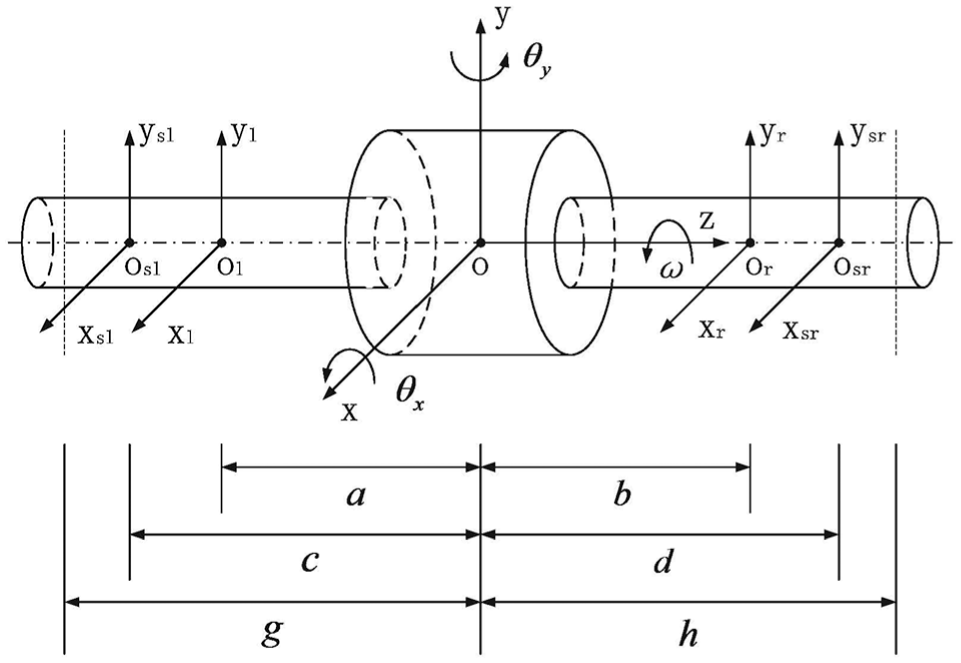
Schematic model of the rotor.
Using the assumptions mentioned in Ouyang et al., 4 the equations of translational and rotational motions for the rotor system are 1


where the parameters
The above equations can be represented as follows

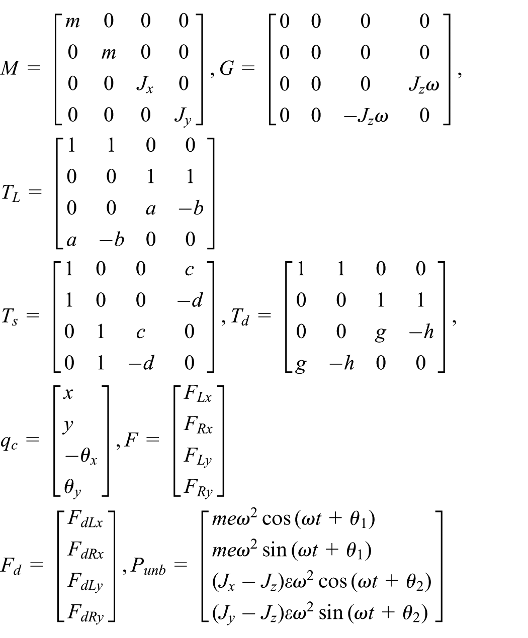
The parameters e,
On the other hand, the linearized radial bearing forces F at equilibrium point can be represented as follows 4


where
The dynamic model of the rotor–bearing system can be represented as follows by combining equations (5) and (6)

where

Four-degree-of-freedom magnetic bearing system.
Cross-feedback-based modal decoupling controller design
As mentioned previously, the vibration in the asymmetric rotor system was caused by not only the gyroscopic coupling but also by the modal coupling due to the asymmetric system parameters. Meanwhile, the mass unbalance and external loads are also the major reasons causing rotor vibration. Many methods have been proposed to solve the aforementioned problem. However, the traditional decentralized control and centralized control showed worst control performance, especially the decoupling performance. Hence, a cross-feedback-based modal decoupling controller is proposed for suppressing the vibration of the magnetic suspended flywheel energy storage system.
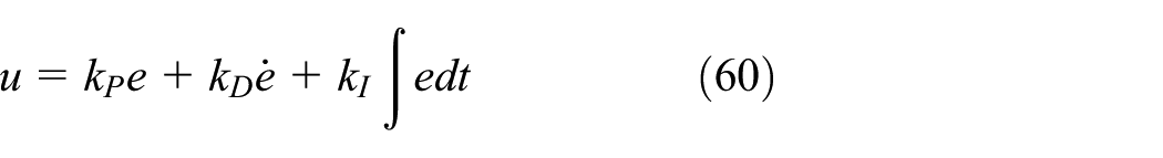
The following PID controller is applied to each DOF of the rotor system

where
Subsisting equation (8) into equation (7) and using the Laplace transform, we have

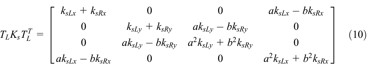


It is obvious that the equations of motion of the above system are coupled in each DOF by the gyroscopic matrix G and other matrixes.
Firstly, a cross-feedback controller is designed to compensate for the gyroscopic coupling effect. Because the natural differential coefficients of the differentiators are different, the following differential loops are designed in parallel with the differentiators in the PID controller to compensate for the coupling effect

where
If the conditions


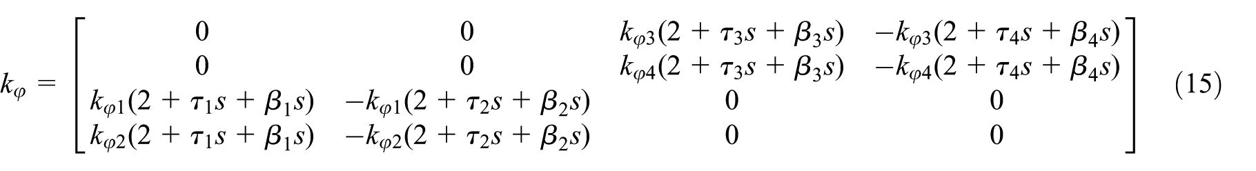
Because the position terms are included in equation (15), the transfer function matrix of the position cross channel is presented as follows

Substituting equation (20) into equation (9) to compensate for the coupling term, we have

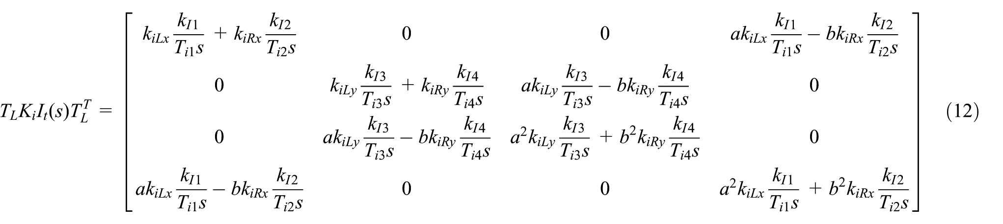
Next, a controller is designed to eliminate the anti-diagonal terms in equations (10)–(13). The following compensator is substituted into equation (9) to compensate for the integral coupling term in equation (12)
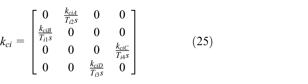
where


Then, the following compensator is substituted into equation (9) to compensate for the differential coupling term in equation (13)

where


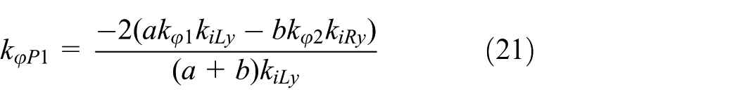
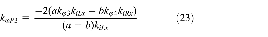
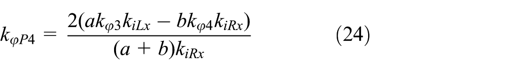
On the other hand, the anti-diagonal terms and proportional terms including those in equations (10), (11), (13), and (30) may affect the control performance of the system; therefore, they should be compensated. The following compensator is designed
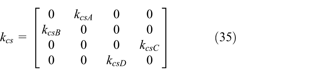
where


It is noted that additional diagonal terms are introduced into equation (9), and the effect on the whole system caused by these terms should be considered. Generally, the selection of PID controller coefficients is made based on the design stiffness and damping of the AMBs. If the transfer function matrices of the system include the aforementioned terms, the controller coefficients of each channel may change. Indeed, the whole system becomes unstable.
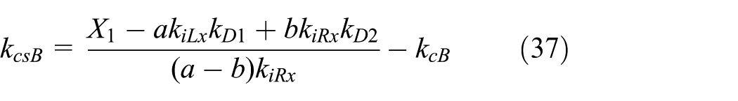
First, the following compensator is designed to compensate for the additional diagonal terms caused by equation (25)

where


Then, the following compensator is designed to compensate for the additional diagonal terms caused by equation (30)
where


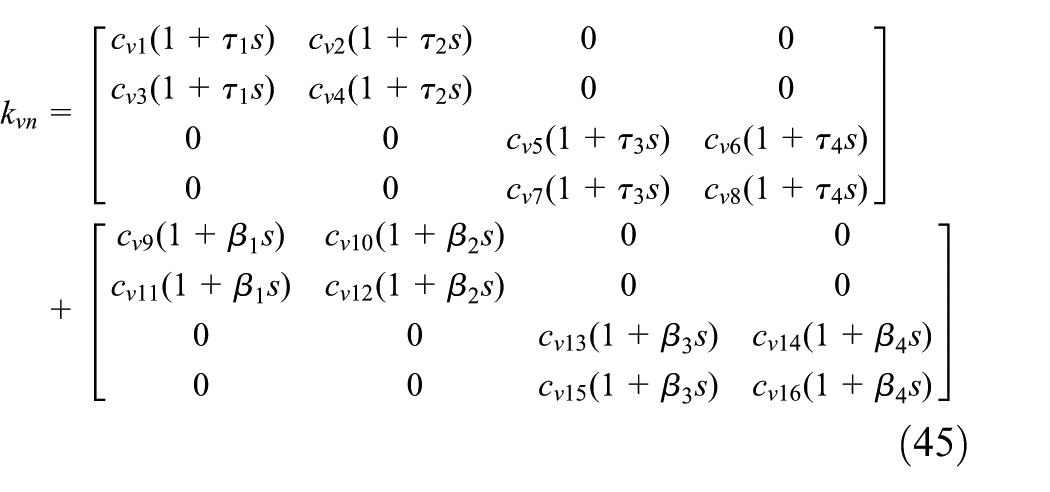
In the same manner, the following compensator is designed to compensate for the additional diagonal terms caused by equation (35)

where


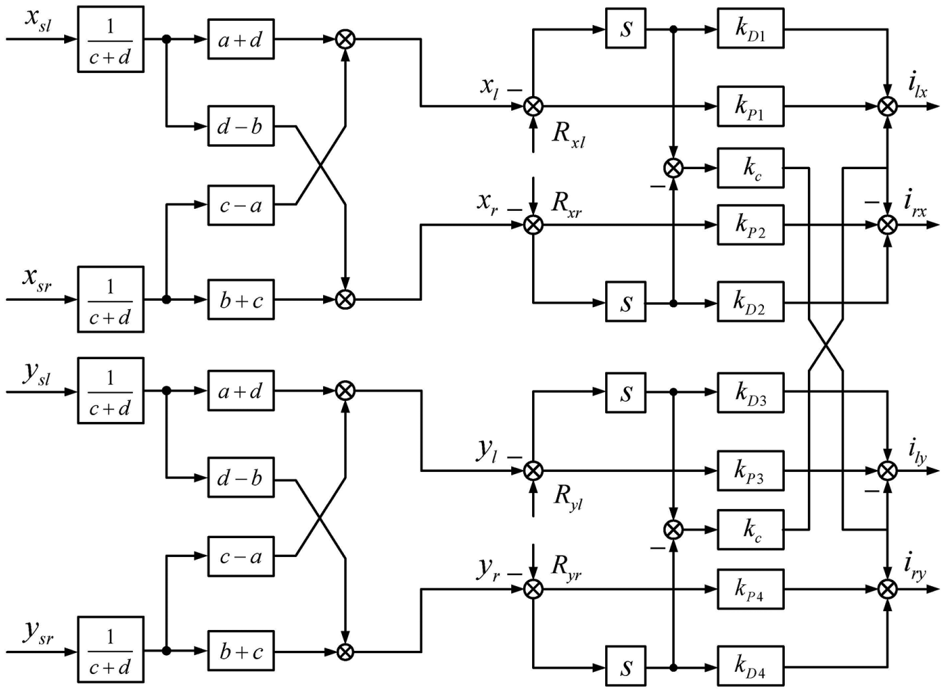
Hence, the proposed control system shown in Figure 3 can be represented as follows


The proposed controller.
Simulation results
To demonstrate the effectiveness of the proposed controller, we carried out several simulations via ADAMS–MATLAB co-simulation technology for improving the simulation accuracy in this section.
ADAMS model for the rotor–bearing system
ADAMS is the most widely used dynamic simulation software, and SOLIDWORKS has a powerful three-dimensional (3D) modeling function as well as a good connection with ADAMS. In this article, we built the 3D model of the flywheel–rotor–bearing system via SOLIDWORKS which is shown in Figure 4, and this is the major part of the real system shown in Figure 19. The corresponding material information for each part of the model is shown in Table 1.

Three-dimensional model of the flywheel–rotor–bearing system.
Material coefficients of the rotor–bearing system.
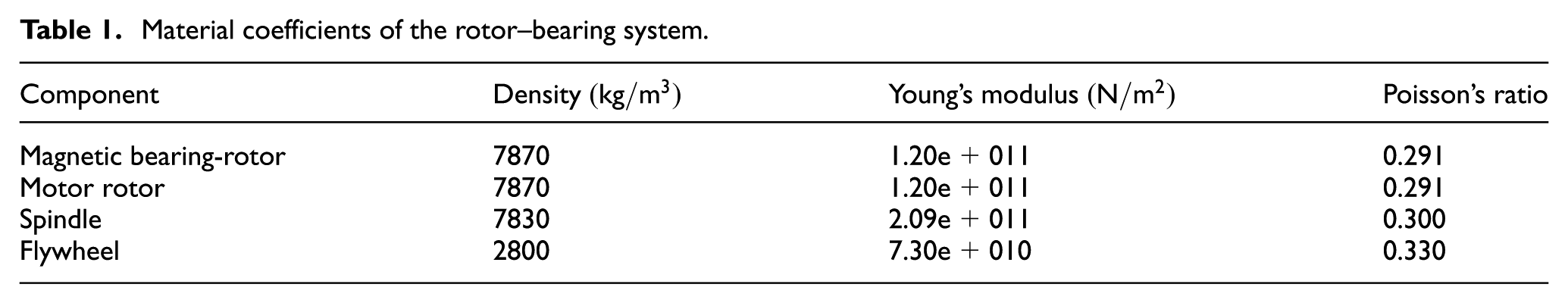
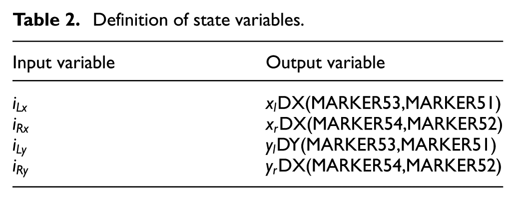
After defining the material information, the rotor system has mass information, center of mass, and moment of inertia which can be calculated through ADAMS software, and we established the coordinate system in the center of mass. In order to make the rotor suspend based on our requirements, we also need to add motion constraints for each part of the rotor. Considering physical applications, we added fixed constraint between the spindle and other parts such as bearing-rotors, motor rotor, and flywheel. We also add rotational constraints to the rotor itself. For defining the constraints of the rotor conveniently, we marked four points, which are MARKER51–MARKER54, respectively. Eight variables including four input variables and four output variables, which are shown in Table 2, were set up. Then, the ADAMS model of the rotor–bearing system is shown in Figure 5.
Definition of state variables.
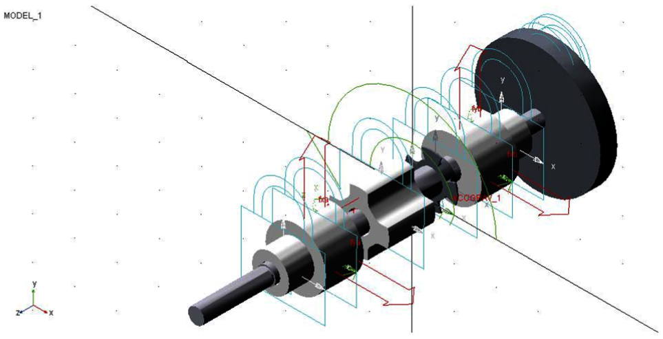
ADAMS model of the flywheel–rotor–bearing system.
Comparative controller and simulation conditions
To demonstrate the effectiveness of the proposed controller, comparative simulations were conducted by a traditional decentralized PID controller and a cross-feedback controller which are classical decentralized control strategies. The PID controller for each DOF magnetic bearing was designed as follows 17
where u, e,
On the other hand, the cross-feedback controller was designed as shown in Figure 6 which is based on the theory reported in Markus et al.
18
The cross coefficient
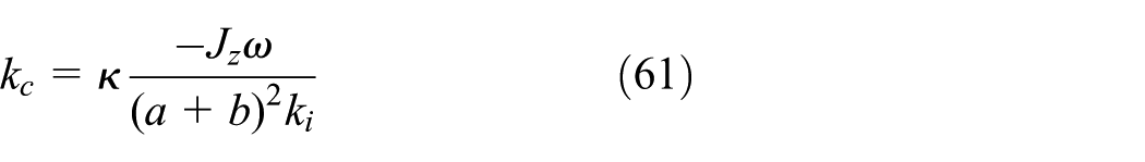
The coefficient


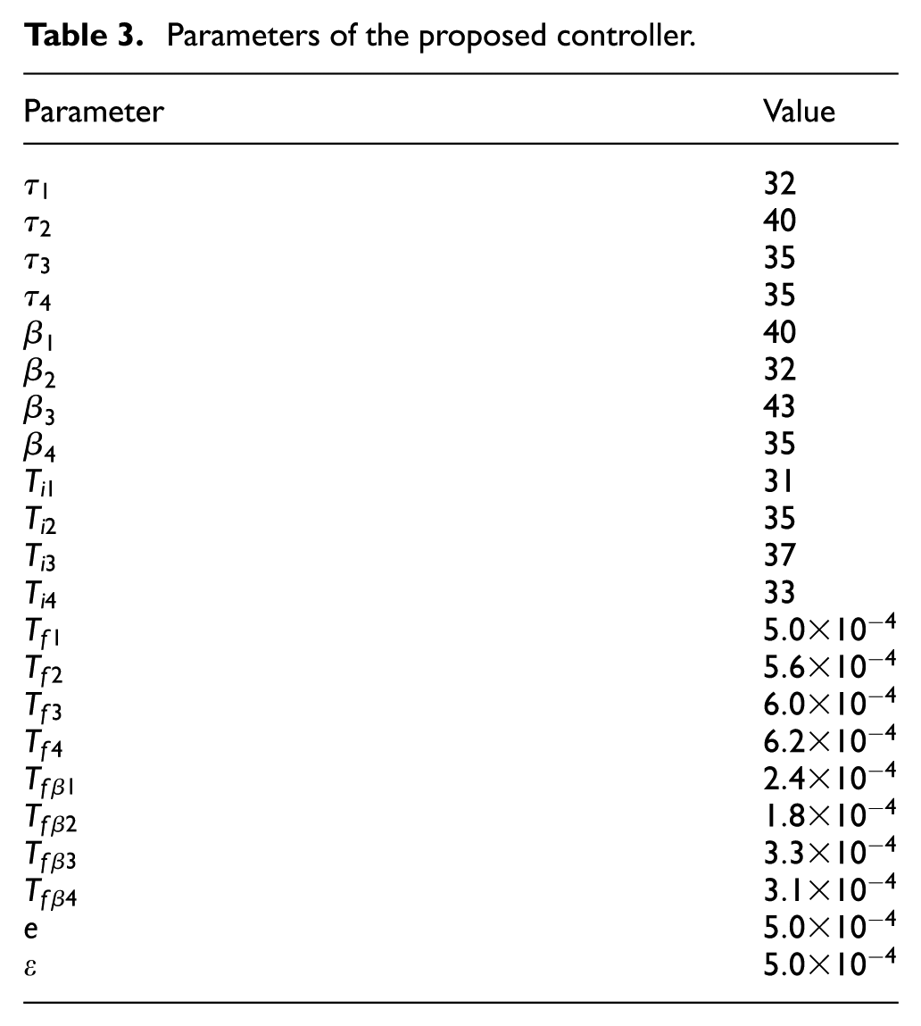
and the rest of the parameters of the proposed controller are shown in Table 3.
Structure of the cross-feedback controller.
Parameters of the proposed controller.
The initial position for
Parameters of the rotor–bearing system.

Note: The ‘N/A’s are the unit of the current stiffness kiLx, kiRx, kiLy and kiRy, which are the same meanings as others in this table.
Control performance
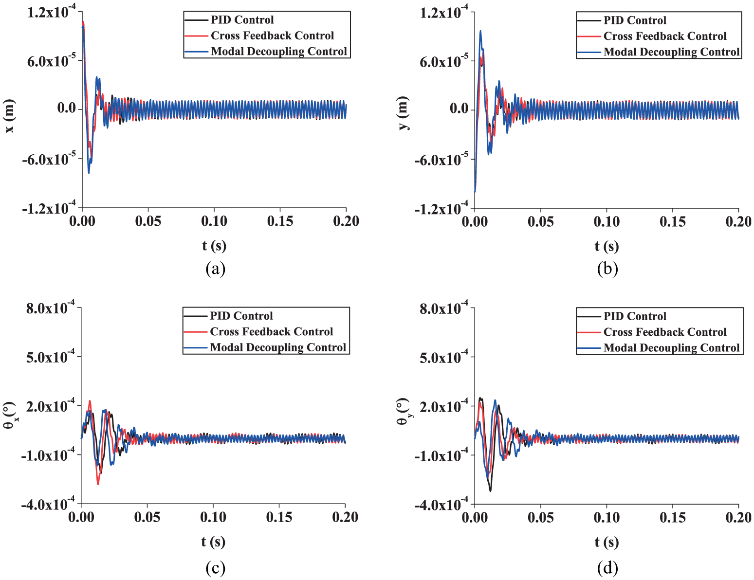
The control performance results for position x, position y, angular position
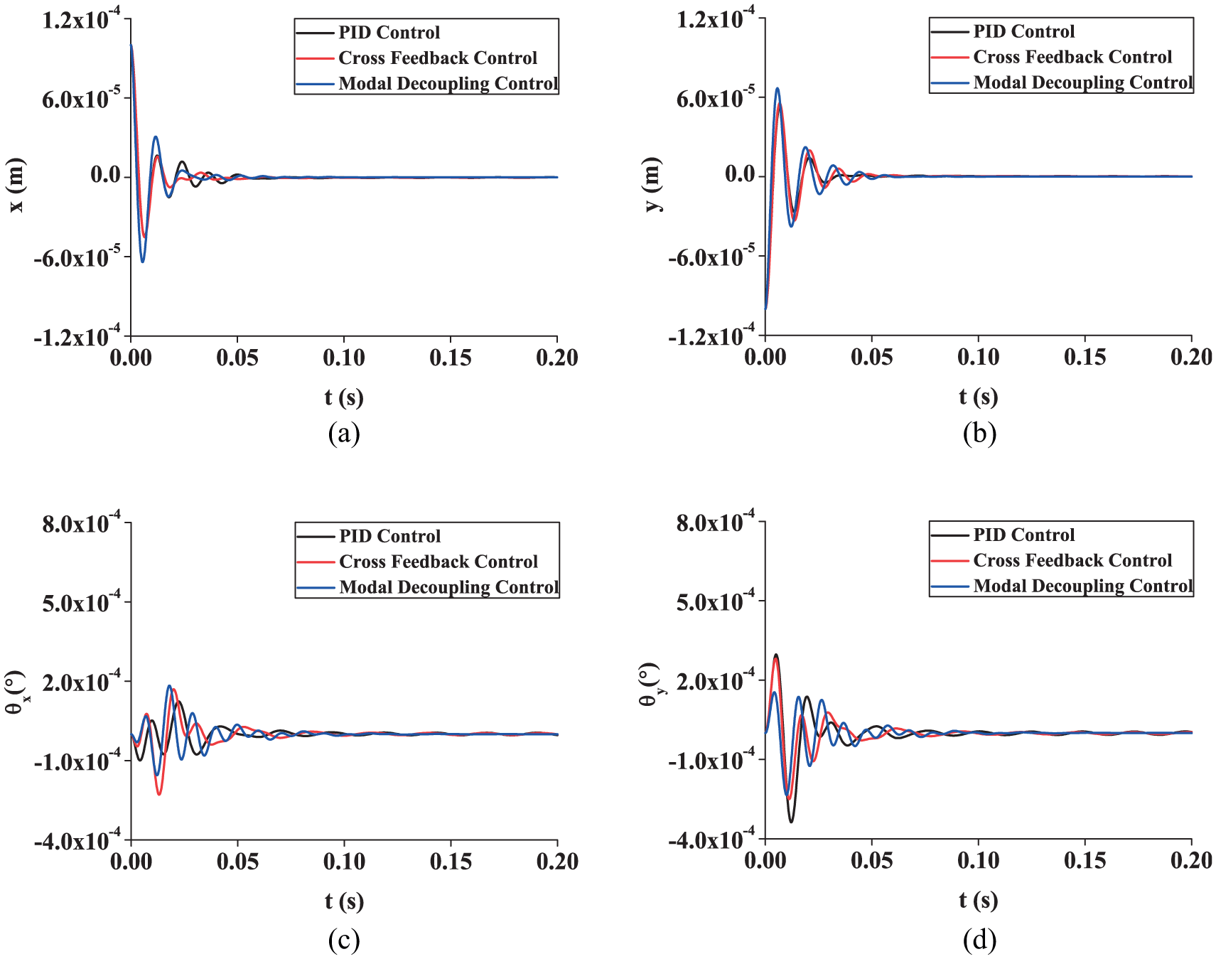
Response trajectory of center of mass of the rotor (ω = 25,000 rpm) (control performance): (a) position x, (b) position y, (c) angular position θx, and (d) angular position θy.
Comparison of control performance.
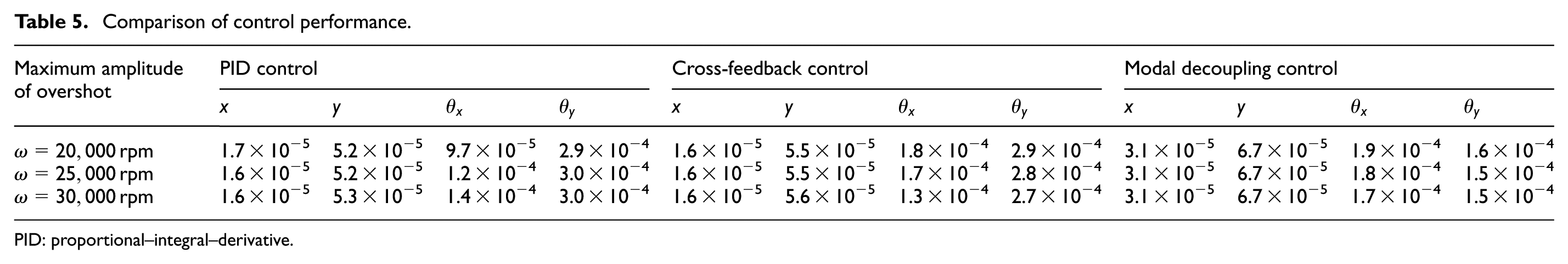
PID: proportional–integral–derivative.

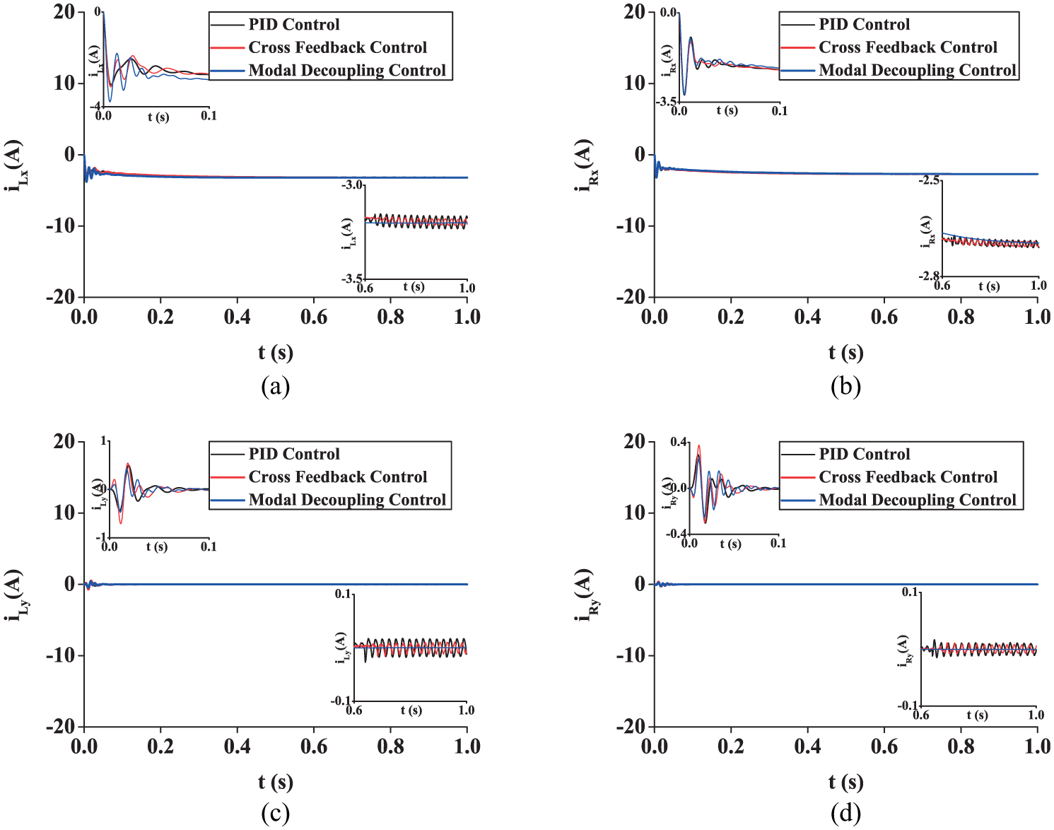
Control current (ω = 25,000 rpm) (control performance): (a) control current of the left-side bearing in the x-direction, (b) control current of the right-side bearing in the y-direction, (c) control current of the left-side bearing in the y-direction, and (d) control current of the right-side bearing in the y-direction.
The control performance results under the conditions

Response trajectory of center of mass of the rotor (ω = 20,000 rpm) (control performance): (a) position x, (b) position y, (c) angular position θx, and (d) angular position θy.

Response trajectory of center of mass of the rotor (ω = 30,000 rpm) (control performance): (a) position x, (b) position y, (c) angular position θx, and (d) angular position θy.
Decoupling performance
In order to ensure that the magnetic suspension rotor will not impact the stator in the process of movement, the maximum force whose size is

Response trajectory of center of mass of the rotor (ω = 25,000 rpm) (decoupling performance): (a) position x, (b) position y, (c) angular position θx, and (d) angular position θy.
Comparison of decoupling performance.

PID: proportional–integral–derivative.
Control current (ω = 25,000 rpm) (decoupling performance): (a) control current of the left-side bearing in the x-direction, (b) control current of the right-side bearing in the y-direction, (c) control current of the left-side bearing in the y-direction, and (d) control current of the right-side bearing in the y-direction.
The decoupling performance results under the conditions

Response trajectory of center of mass of the rotor (ω = 20,000 rpm) (decoupling performance): (a) position x, (b) position y, (c) angular position θx, and (d) angular position θy.

Response trajectory of center of mass of the rotor (ω = 30,000 rpm) (decoupling performance): (a) position x, (b) position y, (c) angular position θx, and (d) angular position θy.
Disturbance rejection performance
In practical applications, external disturbance such as imbalance force always affects the system stability and control performance. Hence, the designed controller should satisfy the disturbance rejection requirement. In this section, we conducted several simulations considering the imbalance force terms in equation (1). The disturbance rejection performance results for position x, position y, angular position
Response trajectory of center of mass of the rotor (ω = 25,000 rpm) (disturbance rejection performance): (a) position x, (b) position y, (c) angular position θx, and (d) angular position θy.
Comparison of disturbance rejection performance.

PID: proportional–integral–derivative.

Control current (ω = 25,000 rpm) (disturbance rejection performance): (a) control current of the left-side bearing in the x-direction, (b) control current of the right-side bearing in the y-direction, (c) control current of the left-side bearing in the y-direction, and (d) control current of the right-side bearing in the y-direction.
The disturbance rejection performance results under the conditions

Response trajectory of center of mass of the rotor (ω= 20,000 rpm) (disturbance rejection performance): (a) position x, (b) position y, (c) angular position θx, and (d) angular position θy.

Response trajectory of center of mass of the rotor (ω= 30,000 rpm) (disturbance rejection performance): (a) position x, (b) position y, (c) angular position θx, and (d) angular position θy.
Experimental verifications
To demonstrate the effectiveness of the proposed controller, we also carried out several experimental verifications with the same parameters and conditions as used in the simulations.
Experimental system
The experimental system shown in Figure 19 includes many parts such as magnetic bearings, motor, flywheel, and dynamometer. The control system shown in Figure 20 for the flywheel system includes a TMS320F28335 digital signal processor (DSP), power amplifiers, control coils, eddy current position sensors, and signal condition circuits.

Experimental system.
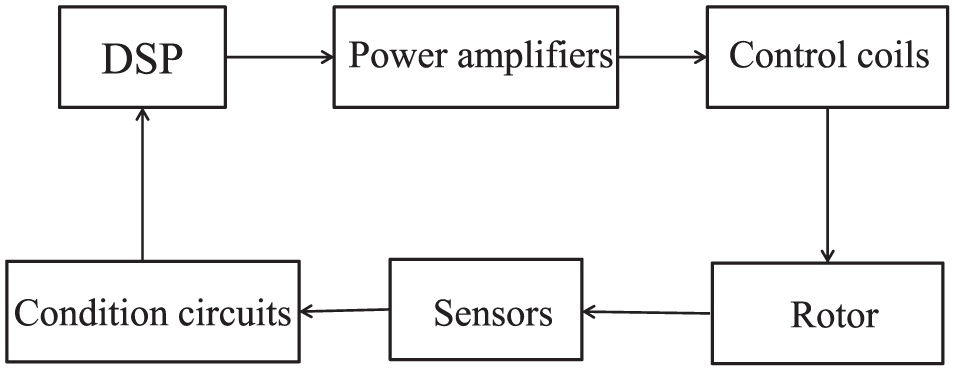
Control system.
Experimental results
Because the imbalance force of the actual magnetic suspended flywheel storage system always exists, we just need to analyze the control performance and decoupling performance of this system in experiments.
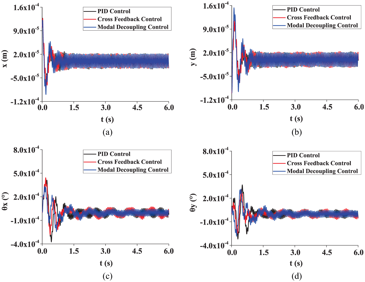
The control performance results for position x, position y, angular position

Response trajectory of center of mass of the rotor (ω = 25,000 rpm) (control performance): (a) position x, (b) position y, (c) angular position θx, and (d) angular position θy.

Response trajectory of center of mass of the rotor (ω = 20,000 rpm) (control performance): (a) position x, (b) position y, (c) angular position θx, and (d) angular position θy.
Response trajectory of center of mass of the rotor (ω = 30,000 rpm) (control performance): (a) position x, (b) position y, (c) angular position θx, and (d) angular position θy.
The decoupling performance results for position x, position y, angular position

Response trajectory of center of mass of the rotor (ω = 25,000 rpm) (decoupling performance): (a) position x, (b) position y, (c) angular position θx, and (d) angular position θy.

Response trajectory of center of mass of the rotor (ω = 20,000 rpm) (decoupling performance): (a) position x, (b) position y, (c) angular position θx, and (d) angular position θy.

Response trajectory of center of mass of the rotor (ω = 30,000 rpm) (decoupling performance): (a) position x, (b) position y, (c) angular position θx, and (d) angular position θy.
Conclusion
In order to suppress the vibration caused by gyroscopic coupling, parameter coupling, and imbalance force in a magnetic suspended flywheel energy storage system with an asymmetric rotor, a novel cross-feedback-based modal decoupling controller was designed after deriving the mathematical model of a radial 4-DOF rotor–bearing system. Better performance was obtained through comparing the decoupling performance, control performance, and disturbance rejection performance with a traditional decentralized PID controller and a cross-feedback controller via ADAMS–MATLAB co-simulation technology. The experimental results also verify the effectiveness of the proposed controller.
Footnotes
Handling Editor: Crinela Pislaru
Declaration of conflicting interests
The author(s) declared no potential conflicts of interest with respect to the research, authorship, and/or publication of this article.
Funding
The author(s) disclosed receipt of the following financial support for the research, authorship, and/or publication of this article: This work was supported in part by the National Natural Science Foundation of China under Grant No. 61703202 and the Key Research and Development Project of Jiangsu Province under Grant No. BE2017164.