
Abstract
Recently, magnetic bearings have been applied to many rotating machines such as turbo-molecular pumps, cooling gas compressor, flywheel energy storage systems. And high-power density is the future development trend of these machines, which demands that the rotor characterizes slender and high rotating speed and operates above the critical speeds. However, it is a big challenge for a flexible rotor to pass the bending critical speeds and operate above the critical speeds steadily and reliably. Based on above reasons, this article presented the design, modeling, and analysis framework of a flexible rotor test rig with active magnetic bearing (AMB). Special attention was paid to the flexible rotor dynamic model development, dynamic analysis, and model-based robust control design. First, the main structure features were illustrated in detail, including the key dimensions and parameters of the AMB components and rotor. Then models of components including power amplifier and displacement sensor were developed. The finite element method based on Timoshenko beam theory was applied to the rotor dynamics model. The dynamic analysis of the rotor is the foundation of the controller design. Hence, modal analysis had been done, obtaining rotor dynamic properties via synthesis of natural frequency, mode shapes, and Campbell plots. Reduced order model was obtained for controller design convenience. A robust H∞ controller was designed based on the system model and controller performance was validated with numerical simulation. The results indicate that the controller has good vibration suppression performance and makes the flexible rotor pass the first bending critical speed.
Introduction
Traditional mechanical bearings exhibit an inherent frictional loss due to the direct contact between stator and rotor, the situation worsens during high-speed rotation resulting extreme mechanical wear and tear, generation of heat, and then structural failure. Active magnetic bearing (AMB) is a novel high-performance bearing which utilizes magnetic force by actively controlling the dynamics of electromagnets to make the rotor suspend stably in an equilibrium position. The AMB has many advantages over mechanical bearings including no direct contact, no friction, no lubrication, lower power consumption, longer life-time, and adjustable support stiffness and damping.1,2 Due to these merits mentioned above, AMB has been widely applied in many high-speed rotating machinery such as high-speed motors,3,4 molecular pumps, 5 centrifugal compressors, 6 and flywheels.7,8 With the development of the industry, new design demands are aroused for rotating machinery such as high energy density, small size, and lightweight. In order to meet these requirements, introducing flexible rotor design is very promising solution, as rigid rotors fail to meet these demands. In comparison to rigid rotor, flexible rotors can reach higher speed and greatly reduce the weight of the machine, which will make them more suitable for motors, compressors, high-speed spindle, and aerators. For example, spindle drives in machine tools and turbo-molecular pumps in semiconductor processing plants need high-power and high rotational speeds for time-efficient operation and quality improvements. In cogeneration system including micro gas turbines, high-speed and compact generators are highly required. These high-speed generators can be directly connected to high-speed gas turbines without gears. The system can be compact and less expensive. In compressor drives, high-speed motors can be directly connected to the shaft without gears. Hence, machines with flexible rotor characterize with merits of compactness, lightweight, high efficiency, and maintenance-free operation. 9 However, the flexible rotor usually has to cross the bending critical speeds before reaching its rated rotational speed. The rotor amplitudes will have a sharp increasing due to the light damping when the rotor speed is passing one of its natural frequencies. The rotor will become unstable if rotor displacement exceeds the air gap of the auxiliary bearing. Therefore, the demand to suppress the flexible rotor vibration at bending frequency brings new challenges to the controller design.
Generally, providing enough damping is a promising solution to suppress rotor vibration. Some researchers resort to additional active or passive dampers.10,11 Additional magnetic dampers have effective suppression on the resonance of the rotor to pass the bending critical speed. However, the dampers need to occupy extra space that will add extra mass and volume of the machine. Another solution to suppressing the resonance of the rotor is to design a controller with better performance making the rotor smoothly cross the bending critical speed.
It is well known that AMB is an inherently unstable system. In most cases, especially in industrial application, PID regulator is introduced. However, using a simple PID controller without additional phase lead compensator would lead to power amplifier voltage saturation. It is difficult to achieve stable operation when the rotor passes the bending critical speed. Mode separation method is proposed to establish the rotor mathematical model and then PID controller is introduced with phase lead compensator and notch filter to successfully make the rotor pass the first bending critical speed in a magnetically suspended motor. 12 In Fang et al. 13 and Tang et al., 14 the optimal damping and optimal phase angle are derived in detail based on the order reduced rotor model with modal truncation, and the design process of the optimal phase compensator is introduced in detail. In Wei and Söffker, 15 multiobjective genetic algorithm is employed to optimize the parameters of PID controller with commonly used filters to suppress the resonance vibration of the flexible rotor, which saves much hand-tuning time.
PID controller is introduced in the references above. However, additional phase lead compensator and notch filter lead to complicated control system. Meanwhile, the parameter uncertainty and unmodeled dynamics have a great influence on the performance of PID controller. Therefore, some researchers try to use model-based advanced control strategies to suppress the rotor vibration such as Linear Quadratic Gauss (LQG), robust H∞ control, μ-synthesis, and sliding mode control.16–22 These MIMO advanced controllers can deliver cross-coupled control to all axes at the same time. Although the application of LQG state feedback control strategy is discussed in Tang et al., 16 taking into account the rotor displacement and power amplifier current to make the displacement and current reach the minimum, the LQG controller can only achieve a balance to meet the needs of designer. And the controller algorithm is relatively complicated and overly dependent on the accuracy of the system model. LQG controller is limited in industrial application. The application of mixed-sensitivity H∞ control design to realize stringent positioning and disturbance rejection is discussed in Lee and Salapaka 23 and Noshadi et al., 24 In addition, a μ-synthesis controller applied to the rotor test rig with cross-coupled stiffness excitation is designed with the help of robust control technology by SE Mushi et al. 25 Although MIMO controller can promote the performance of AMB system, some degree of system modeling accuracy must be guaranteed.
In this article, a transparent procedure to systematically characterize the entire design and modeling of an AMB-rotor system for the purpose of control design is presented. Special attention is paid to the flexible rotor dynamic model construction, dynamic analysis, and model-based control design. The remainder of this article is organized as follows. In section “Design overview,” a design overview of the test rig structure is presented in detail. Section “System modeling” presents the entire system modeling procedure, including rotor dynamic model, AMB actuator model, power amplifier model, and eddy current displacement sensor model. Rotor model reconciliation and validation are presented and the reduced order model is obtained by modal truncation in section “System modeling.” In section “Controller design,” the design procedure of the robust H∞ controller has been described. Section “Conclusion” provides a summary of the work and outlines future investigations.
Design overview
In order to conduct the thorough research work into how to make the flexible rotor pass the bending critical speed, a flexible rotor test rig with AMB is designed. Rotor is a key assembly in the AMB systems. In the design of the rotor, the primary goal is to verify the controller performance. Therefore, the rotor is usually designed to be slender by iterative calculation and optimization so that the rotor can reach the first bending critical speed at a lower speed and match the common properties of the above-mentioned rotating machines. The mechanical configuration of the flexible rotor designed in this article is shown in Figure 1.

Flexible rotor.
The rotor was machined as a single piece with three discs and laminations to be mounted. Due to that the rotor material is stainless steel, two detection rings made from 45# steel were mounted onto the rotor for displacement detection conveniently. Three laminated silicon-steel journals were mounted onto the rotor. The radial AMB at mid-span location C was used to simulate different forms of interference. The final design was a 1-m-long rotor with a mass of 19.55 kg.
The radial stators of AMB A and B with eight-pole structure and designed lifting capacity of more than 500 N were designed to support the rotor based on the rotor mass and unbalanced force. The AMB is composed of stator and rotor part. The stator material was laminated silicon-steel. The magnetic system of radial AMB is divided into four sectors, which ensure rotor positioning in two mutually perpendicular directions (x- and y-axes). Each sector consists of two electromagnets. The stator structure is shown in Figure 2. And main parameters of the magnetic bearings are tabulated in Table 1.

Stator structure.
Main parameters of the radial AMB.

The entire flexible rotor test rig configuration is shown in Figure 3. An inverter duty AC motor was selected to drive the rotor via a flexible coupling. Some peripheral components such as digital signal processing (DSP) chip, power amplifiers, host computer are also included (not be displayed in Figure 3). Four radial degrees of freedom are limited by two AMBs and the axial degree of freedom is limited by the flexible coupling. When the control is off, the rotor is down on the auxiliary bearings.
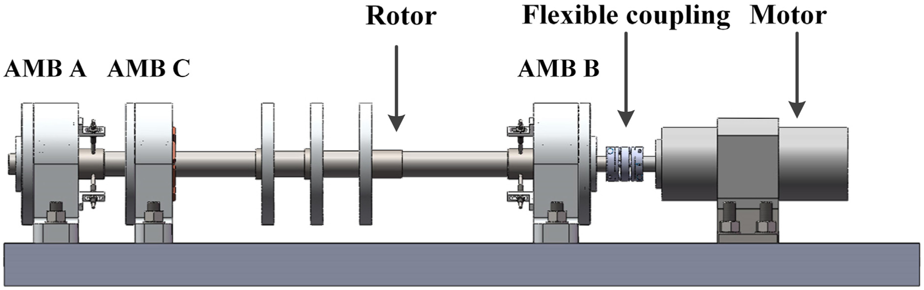
Flexible rotor test rig.
System modeling
The block diagram in Figure 4 shows a typical closed-loop model of the AMB system including controller, power amplifier, rotor-AMB dynamic model and displacement sensor and signals exchanges among different mechatronic components: reference input r, control output u, coil current i, and rotor displacement y.
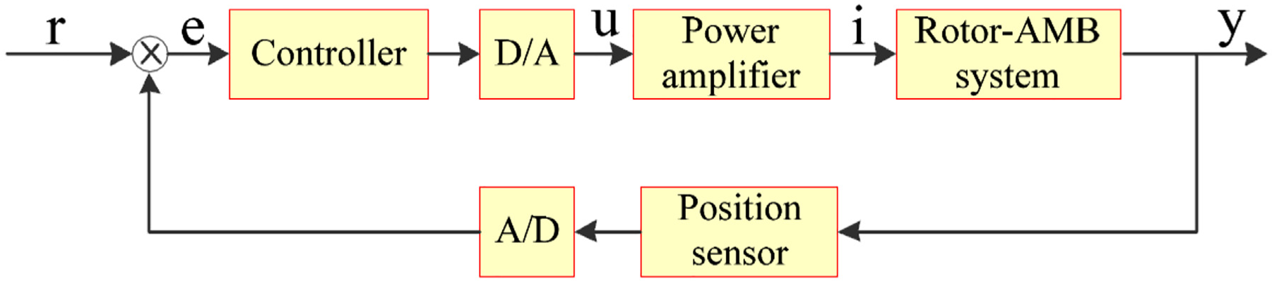
The block diagram of rotor-AMB system.
Modeling of the AMBs
Generally, two counteracting magnets are operated in a bearing magnet. This configuration makes it possible to generate both positive and negative forces. 2 Mathematically, the magnetic force is inherently nonlinear. In order to simplify the control design, an approximate linear model can be expressed as follows

where
Load capacity is a crucial performance index of the AMB. The electromagnetic force of the radial AMBs according to the currents at the normal gap is shown in Figure 5. It can be seen that the maximum lifting capacity of a pair electromagnet is 548.8 N, with a margin of about 9.8% more than the designed value.

Force–current curve and force–displacement curve: (a) Force-current curve, (b) Force-displacement curve.
In order to obtain ki and kx, the force–current and force–displacement curves are plotted in Figure 5 by means of Workbench simulation results. At the operating point, from force–current and force–displacement curves (Figure 5), their respective slopes are determined to be
Modeling and analysis of the flexible rotor
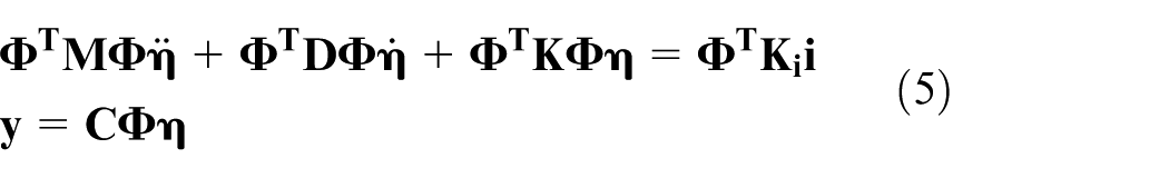
There are two main methods to model the dynamics of flexible rotor, that is, transfer matrix method and finite element method (FEM). Although transfer matrix method is simple, the numerical instability phenomenon tends to arise in the computation process with poor calculation accuracy. The FEM has higher calculation accuracy by means of computer. Therefore, in the present article, the FEM was employed to model the rotor dynamics. A plane model is obtained by dividing the rotor into 49 segments for the lateral dynamic analysis, as shown in Figure 6. According to the lumped mass principle, the additional components are regarded as additional mass and moment of inertia attached to the nodes. Dynamic model of the rotor can be expressed as a second-order system as equation (2)

where

The finite element model of the rotor.
Modal testing and model updating
Modal analysis is an important tool to analyze the rotor dynamic characteristics including theoretical modal analysis and experimental modal analysis. According to the established model described by equation (2), the first four-order undamped natural frequencies are obtained under the free-free condition, to be 0, 0, 134.9, and 406 Hz. The two rigid modal (translational and conical modal) is 0 Hz. However, the addition of the shrunk fit AMB rotors and sleeves has effect on the global stiffness of the rotor, which is difficult to predict, due to many factors such as uncertain friction and pre-stress between different components. Therefore, in order to obtain the final numerical model of the rotor, which accurately describes the actual rotor dynamic characteristics, the FE model needs to be fine-tuned based on modal test results.
Modal test is an effective method to update the rotor model and contributes to better vibration control. The advantage of rotor modal test is that transfer function measurements would be representative of the standalone rotor, which allow for modeling much simpler. To obtain actual rotor modal frequency, LMS vibration test system is used to conduct the modal test. The rotor is hung with an elastic rubber rope to simulate free-free state. One acceleration sensor is attached to the rotor surface with glue. The first two experimental bending modal frequencies are used to update the rotor model, which we are interested in. Therefore, the accelerometer is placed far away from their modal nodes to obtain their frequencies easily. Pulse excitation signal generated by exciting hammer and acceleration signal collected by acceleration sensor are sent to the host computer. In modal testing, the weight of the accelerometer is 1.13 g without cable. The accelerometer weight is much smaller compared to the weight of rotor of 19.55 kg. In general, the influence of the accelerometer on rotor model is ignored. Finally, we can obtain the first two bending modal frequency by modal test, as shown in Figure 7.

Modal testing: (a) Testing depiction, (b) Testing results.
In order to reduce the model error, model updating method is introduced. Generally, physical parameter of material is a constant such as density, mass, and Young’s modulus (E). However, element stiffness diameter is an engineering assumption. Therefore, theoretical computation results can be matched to the experimental results by changing the stiffness diameter of some elements. After an iterative modification, the final experimental results and the reconciled results are listed in Table 2.
Reconciled results.

Free-free undamped modal shape of the rotor at zero support stiffness is shown in Figure 8. In order to obtain good observability and controllability from control point of view, AMBs and the sensors should be placed far from the node. Referring to Figure 8, it is noticed that the first bending modes are clearly observable and controllable.

Modal shape of the rotor.
Analyzing the rotor critical speed as it is affected by the supporting stiffness is very important in predicting the resonance interval. Rotor critical speeds under different supporting stiffness are obtained as shown in Figure 9 since the supporting stiffness is dependent on active control parameters for some degree. However, gyroscopic effects were excluded. Figure 9 indicates that when the support stiffness is small, the rotor modal frequency is not sensitive to support stiffness changes. The support stiffness has a great influence on the rotor modal frequency within the range of middle support stiffness. Within the range of high support stiffness, support type being similar to hinge, the rotor material has great influence on modal frequency, whose modal frequency is not sensitive to the stiffness change.
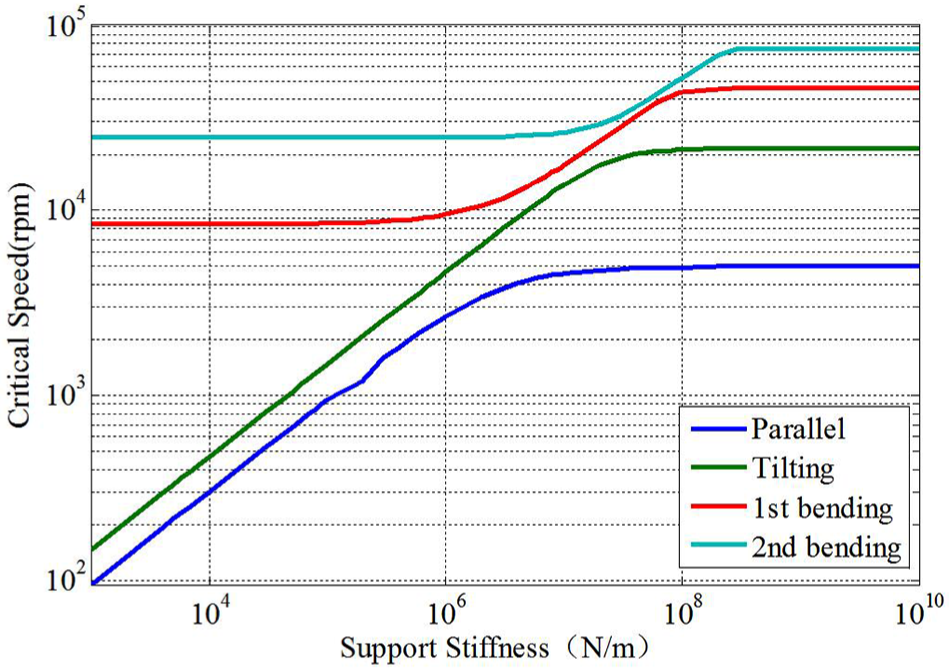
Relationship between critical speed and support stiffness.
A Campbell diagram (Figure 10) was drawn for 3 × 10⁶ N/m support stiffness, which could be computed through structure and control parameters. It is indicated that each natural frequency branches to forward and backward modes as rotational speed is increased under the influence of the gyroscopic effect. The dashed line indicates running speed. When it intersects with the rotor natural frequencies, synchronous vibration will result. It is very important to avoid the resonance range for operating rotor.
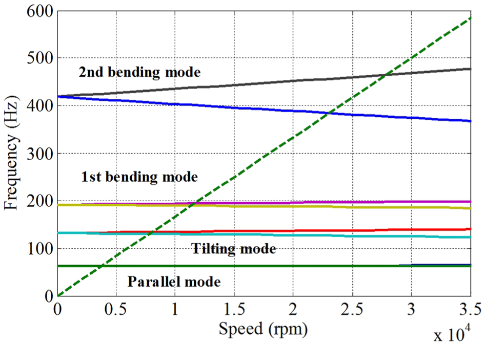
Campbell diagram of the rotor.
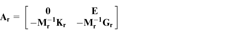
Algorithms for the design of the controller presume plant models with much fewer equations than FE models have. The resulting large set of equations of an FE model is impractical as a simulation tool or control plant model. Hence, a means of reducing the large set of the FE equations are introduced. This is generally done by a truncated modal representation.
All of the previously cited FE analysis studies were based on the utilization of the physical coordinates which results in a large dimensionality. Therefore, modal analysis was conducted to separate modals of the rotor and the interested lower ones were preserved. The detailed procedure is as follows.
Substituting equation (1) into equation (2) will result us equation (3) (gyroscopic effects were excluded)

where
The modal transformation is described as

where Φ donates the modal matrix that comprises a selected subset of the resulting real eigenvectors. If the modal matrix contains only a truncated set of significant modes, the corresponding truncated form is as follows
Then the reduced order model can be written as

The modal coordinate

Where


Modeling of power amplifier
Power amplifier is a key component of the closed-loop system, which receives control voltage and generates enough current for AMB coils. The power amplifier dynamics is affected by the inductance of AMB coils and DC-bus voltage U. Therefore, the resistance R, inductance L of coils, and DC-bus voltage U should be tested before obtaining the frequency response of power amplifier. The R, L, and U are respectively 0.9 Ω, 9.712 mH, and 100 V when the rotor is centered in the air gap with the help of copper foil. The dashed line in Figure 11 indicates the frequency response of power amplifier when a sine sweep voltage is injected into the reference input. The transfer function fitted to the experimental frequency response is as follows

where Ka = 1, Ta = 0.00008, ωa = 620 Hz, and ξ = 0.49. The gain of the power amplifier is set to be 1 A/V. Since all amplifiers are alike, one transfer function is representative of each of their individual performance characteristics. The transfer function Ga(s) can be converted into a state-space model as shown


Frequency characteristic of power amplifier with experimental and theoretical model.
Modeling of displacement sensor
Four differential eddy current displacement sensors are used to measure the rotor radial motion. According to the frequency response curve provided by the sensor manufacturer, the transfer function can be expressed as

where
Equation (10) can be transformed into state-space form

Controller design
AMB is an inherently unstable system, which needs an active controller to stabilize the rotor. Minimizing the adverse effect of modeling uncertainty, steady-state error, noise, and disturbances is the goal of control synthesis. Mixed-sensitivity H∞ robust control algorithm is quite suitable for a practical control system with great engineering significance for it can take account of disturbance and modeling uncertainty at the same time. Meanwhile, control performance can be balanced by means of selecting proper weighting functions. A bound on a single sensitivity function, such as the output sensitivity takes the form of
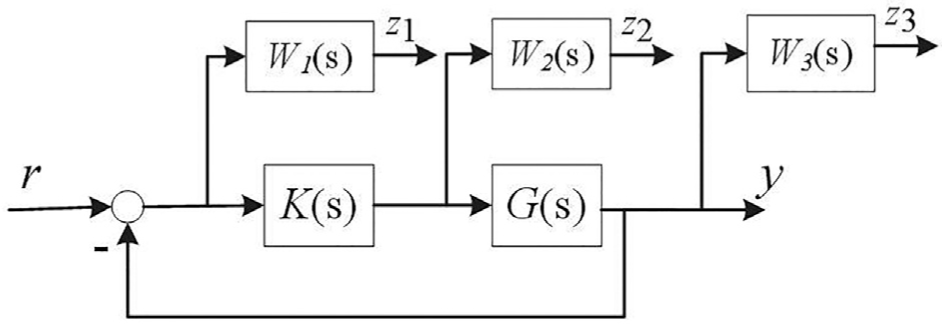
Configuration of H∞ control with weighting function.
G(s) is the control plant, K(s) is the controller stabilizing the rotor, and W1(s), W2(s), and W3(s) are weighting functions shaping the closed-loop behavior of the system. W1(s) is designed to bound the sensitivity function S(s) (S(s) = I/(I + G(s)K(s)) to minimize the steady-state error and ensure the rejection of low-frequency disturbance. W3(s) is designed to bound the complementary sensitivity function T(s) (T(s) = G(s)K(s)/(I + G(s)K(s)) to ensure robust stability against model uncertainty mainly including high-frequency unmodeled dynamic characteristics. Finally, W2(s) can be designed to restrict the control output to avoid saturation.
When the control plant G(s) is combined with the weighting functions, a generalized plant P(s) is generated. In H∞ control problem, the closed-loop transfer function can be conveniently presented as a lower linear fractional transformation (LFT)

where P11, P12, P21, P22 are the transfer functions between
In the H∞ robust control synthesis procedure, we seek a controller K(s) that stabilizes the system and minimizes the H∞ norm of the closed-loop transfer functions of the generalized plant

The successful design of weighting functions in the synthesis of H∞ controller is a challenging mission primarily based on engineering experiences. The following tips may contribute to better weighting functions choices:
T1: Generally, W1(s) should be a high-gain low-pass filter with integral characteristic and meet the following requirement

T2: The introduction of W2(s) can make the system to be standard H∞ control problem. Generally, W2(s) is set to be a small positive number to avoid that there is no robust controller to the augmented plant.
T3: W3(s) generally has high-pass characteristics, making the magnitude of complementary sensitivity function T(s) has a certain attenuation in higher frequency band. The roll-off frequency of W3(s) is generally higher than the roll-off frequency of W1(s) and the following requirement should be met

There are fundamental control limitations in rotor-AMB system. The fundamental conservation law in control system analysis and design takes the form of the Bode sensitivity integral. Through feedback, the reduction of sensitivity function magnitude in a given frequency band is accompanied by enhanced disturbance attenuation in that band and an increase in sensitivity or reduction of performance in another frequency band. The H∞ synthesis process can handle the trade-offs between competing goals so that maximum performance may be attained. Hence, we can improve the resonance vibration control performance at the bending mode frequency by compromising the control performance in a lower frequency band.
Finally, based on the above tips, the final weighting functions for one channel are as follows

The MIMO diagonal weighting functions matrices

Singular value of 1/w1, S.
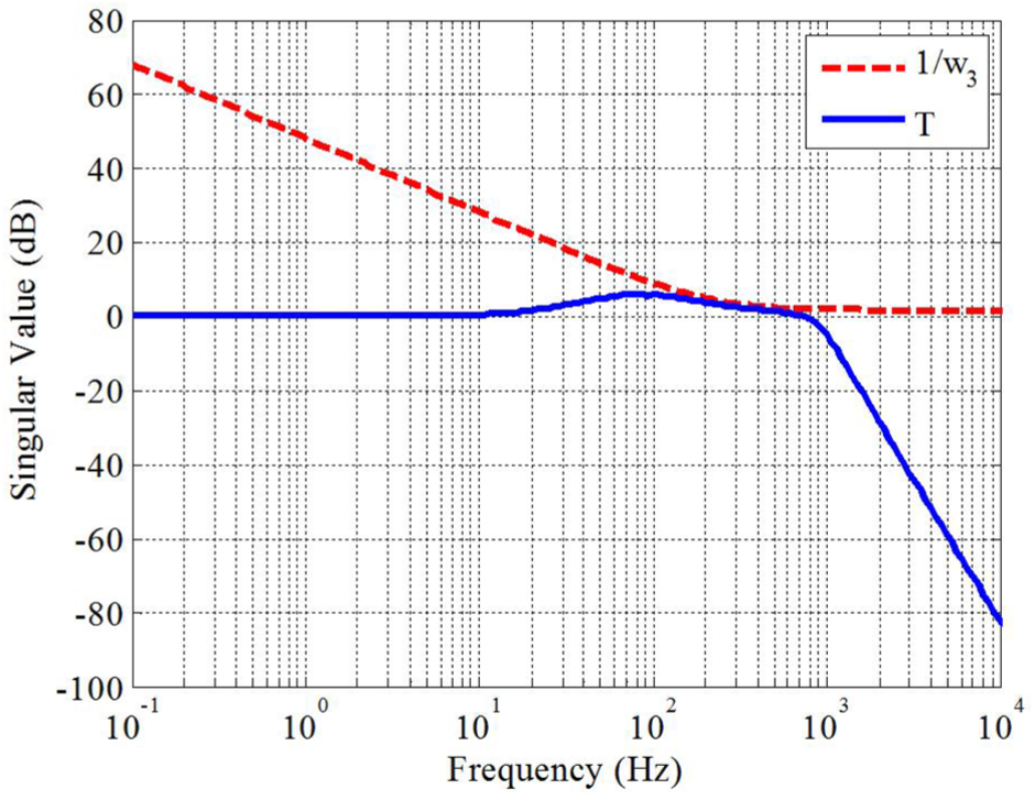
Singular value of 1/w3, T.
The singular value of S(s) is below 1/w1. It indicates that H∞ controller has better disturbance rejection in low-frequency range. Similarly, the singular value of the T(s) is below 1/w3.
Singular values of closed-loop system with H∞ controller is given in Figure 15. The H∞ norm of the nominal closed-loop system is 0.9526.The closed-loop system has good attenuation to high-frequency noise (such as displacement sensor noise) according to Figure 15.
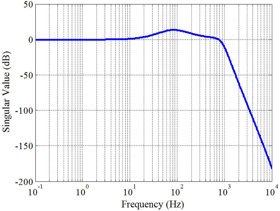
Singular values of closed-loop system.
A MIMO robust controller with 36 states was synthesized. Such a high-order controller needs large amount of calculation and is difficult to implement with lower reliability. Hence, reduced order processing is required. Order reduction method was adopted based on the balanced random truncation. The Hankel singular values of the controller are shown in Figure 16.
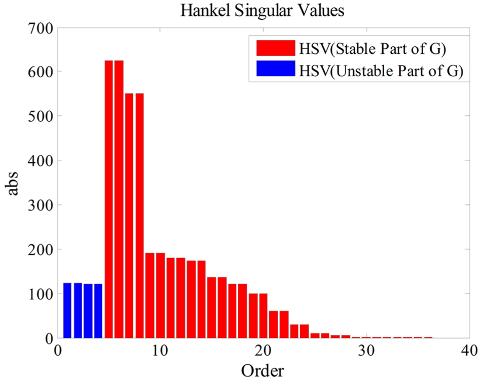
Hankel singular value of the controller.
It is indicated that the first 28 Hankel singular values are larger compared with the residual. Therefore, the latter can be eliminated. Finally, the reduced order controller has 28 states.
The performance of closed-loop system is analyzed in simulation with the reduced order H∞ controller. Figure 17 shows the step response of the rotor representing that the rotor is lifted from the auxiliary bearing.

Step response of closed-loop system.
It is indicated that the rotor is rapidly lifted from auxiliary bearing in 0.013 s. And the rotor has a 32.3% overshot avoiding the contact with the auxiliary bearing during the start-up. Figure 18 shows the step disturbance response of the suspended rotor. It is evident from the figure that the rotor can return to the equilibrium position rapidly and hold steady state again.

Step disturbance of closed-loop system.
Unbalanced force is the main disturbance source of a rotor, which can cause severe vibration when the rotor speed matches its critical speeds. Hence, in order to verify the H∞ controller performance for making the rotor pass the first bending critical speed smoothly, an unbalance of magnitude u = 117.6 g mm located in the middle of the disk 2 was introduced. The harmonic unbalanced force depending on rotor speed in the x direction is shown in Figure 19. With the speed up of rotor from 0 to 24,000 r/min, the rotor displacement at AMB B is shown in Figure 20 and the other freedoms are similar to it. It is shown that there are three peaks arising with the rotor speed increasing which are respectively the first two rigid modes and the first bending mode. Although the controller has a slightly poor performance of vibration suppression in lower frequency range leading to larger rotor amplitude, the maximum amplitude is still less than 160 μm within the security scope. It is quite obvious that the designed H∞ controller has good vibration suppression performance for the flexible mode guaranteeing the rotor pass the first bending critical speed smoothly and stably operate. The steady rotation orbit at the first bending critical speed at the AMB B and AMB A is shown in Figures 21 and 22.
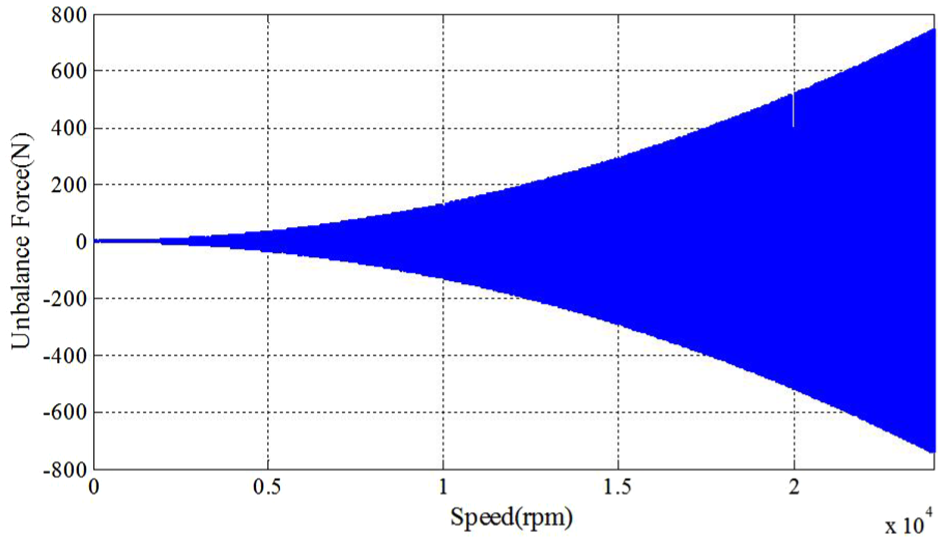
Unbalanced force in the x direction.

Rotor displacement in the x direction.

Rotor orbit of AMB B.

Rotor orbit of AMB A.
Amplifier current saturation and magnetic flux density saturation limit the AMB system performance. When the rotor passes the first bending critical speed, magnetic bearing control forces will have a sharp increment and then amplifier current saturation arises. The rotor is vulnerable to instability in this situation. Hence, control current must be verified during the rotor speed up. The designed maximum current of AMB system is 5 A and the bias current is 2.5 A as mentioned above. Therefore, the control current must be within ±2.5 A avoiding current saturation. The sampled control current of four freedoms near the first bending critical speed is shown in Figure 23.
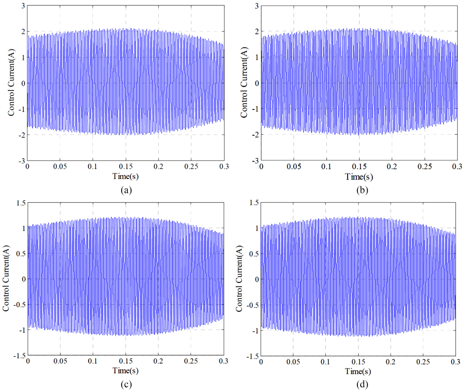
Control current of AMBs: (a) control current in the x direction of AMB B, (b) control current in the y direction of AMB B, (c) control current in the x direction of AMB A, and (d) control current in the y direction of AMB A.
Conclusion
In this article, a detailed design and modeling frame for flexible high-speed rotor supported by active magnetic bearings was presented and an efficient framework of synthesizing robust controllers for flexible high-speed rotor subject to resonant vibration via mixed-sensitivity H∞ control. It is demonstrated that modal test effectively contributes to the rotor model accuracy, which is very important for model-based robust control. A mixed-sensitivity H∞ controller was designed through multiply fine-tuning the uncertainty weighting functions. The numerical simulation results demonstrated that the controller made a performance trade-off between low-frequency band and high-frequency band, resulting in good vibration suppression performance at the resonant frequency; the results confirms the effectiveness of the controller and the flexible rotor passes the first bending critical speed smoothly with lower vibration amplitude. Meanwhile, the controller effectively prevents actuators current saturation.
Footnotes
Handling Editor: Aditya Sharma
Declaration of conflicting interests
The author(s) declared no potential conflicts of interest with respect to the research, authorship, and/or publication of this article.
Funding
The author(s) received no financial support for the research, authorship, and/or publication of this article.