
Abstract
In order to achieve high motion accuracy and better robustness of the rocket launcher position servo system driven by a permanent magnet synchronous motor, a passivity-based controller based on improved active disturbance rejection control is proposed in this article. The convenient method of interconnection and damping assignment and passivity-based control is adopted to establish the port-controlled Hamiltonian system with dissipation model of permanent magnet synchronous motor. To further enhance the robustness and adaptability of the traditional active disturbance rejection controller, an improved active disturbance rejection control strategy–based radical basis function neural network is introduced to on-line update the proportional and derivative gains of improved active disturbance rejection controller. The results of numerical simulation and bench test indicate that the proposed improved active disturbance rejection control passivity–based control algorithm has advantages of smaller overshoot, fast response, small steady-state error, and strong robustness. It proves that the proposed control scheme is effective and suitable.
Keywords
Introduction
Permanent magnet synchronous motors (PMSMs) have been widely applied as servo motors in high-dynamic and high-precision applications, owing to their advantages over other motors, such as simple mechanical structure, high power density, high torque-to-inertia ratio, high efficiency, fast response, and reliable operation.1–4 Meanwhile, alternating current (AC) position servo system of rocket launcher is an extremely complicated system with strong nonlinearities and many uncertainties, such as widely changing moment of inertia and load moment, strong impact moment, and variable parameters of control system induced by its varying working conditions. The motion accuracy and the robustness of the rocket launcher position servo system are regarded as two important challenges to achieve better performance.5,6 However, due to the inherent nonlinearities and the unavoidable uncertainties of the rocket launcher position servo system, it is very difficult to achieve higher control precision and higher quality effect by means of a traditional vector control method.7,8
Along with the development of nonlinear theory, various effective control theories have already been investigated for the position servo system of PMSM, such as sliding mode control, fuzzy-sliding mode control, nonlinear sliding mode control, passivity-based control (PBC), adaptive control, predictive functional control, explicit model predictive control, iterative learning control, robust control, and recurrent Elman neural network.9–19 However, the above-mentioned advanced control methods have the merits and drawbacks, respectively, which can significantly improve the robustness of control system, but at the expense of its motion accuracy. For instance, the robustness of sliding mode control comes at the cost of the well-known chattering and the phase delay.
In order to obtain high-dynamic tracking accuracy, a novel effective control strategy is needed to resolve the conflicts between the motion accuracy and the robustness of the servo control system. Fortunately, active disturbance rejection control (ADRC) is a novel robust control method, which has been successfully applied in motor drive system for about 10 years.8,20–22 ADRC does not depend on the accurate plant model, and it has some advantages, such as fast response speed, better robust, and high control precision. However, although ADRC has strong robustness and good adaptability, the control parameters of ADRC controller are needed to be continuously adjusted to obtain better performances during the control process, which lead to poor operation. Then, the ADRC-based control schemes for PMSM have been reported in the control research literatures, such as fuzzy-adaptive disturbance rejection control and sliding mode–adaptive disturbance rejection control.7,13
Ortega et al. 23 first developed a new PBC theory, which is called interconnection and damping assignment and passivity-based control (IDA-PBC). Petrovic et al. 24 first applied the IDA-PBC controller for PMSMs. It can be easy to design and analyze stability of the system controller with IDA-PBC, for its “almost” global stability. Nowadays, a passive control method receives more and more recognition and application. 25
The remaining part of this article is organized as follows: The port-controlled Hamiltonian system with dissipation (PCHD) model of PMSM is established in section “The PCHD model of PMSM.” The primary concept of ADRC is introduced briefly in section “A preliminary to ADRC.” A passivity-based controller is designed for PMSM in section “The PBC system of PMSM.” A passivity-based controller based on improved active disturbance rejection control (IADRC) is applied for rocket launcher position servo system. Aiming to enhance the control performance, an on-line radial basis function neural network supervision (RBFNNS) is adopted to optimize the control parameters of IADRC in section “The IADRC-PBC controller design.” The proposed approach is verified using MATLAB/Simulink in section “Simulation result and analysis.” The effectiveness of the proposed method is verified by a series of tracking experiments, which is conducted on the semi-physical simulation platform in section “Semi-physical simulation test.” Finally, some conclusions are presented in section “Conclusion.”
The PCHD model of PMSM
Principle of the PCHD system
The structure of diagram of an AC servo system is given in Figure 1, where the bad effects of working conditions, disturbances, and environmental changes are not described. The mathematical model properties of multivariate, nonlinear, and strong coupling are directly determined by the physical structure of AC motor. However, the complex function of electromagnetic torque is composed of the stator current, the flux linkage of the stator and the rotor, and the electromagnetic parameters of the stator and the rotor, which vary with motor temperature. However, it is very difficult to reach better control performance for PMSM with traditional vector control methods.

The structure diagram of AC servo system.
PCHD system is a kind of passive system, which has attracted more and more attentions by the researchers in control field for its “almost” global stabilization objectives. 26 Port-controlled Hamiltonian (PCH) system is defined as

Energy dissipation is imported in the framework of PCH system by terminating some ports with resistive elements.
Then, PCHD can be presented by
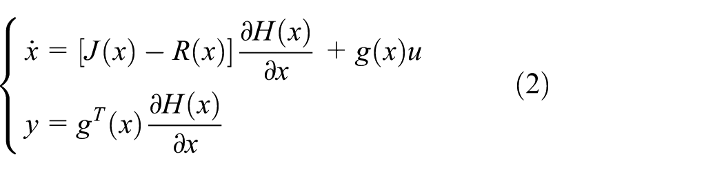
where
PCHD model of PMSM
Regardless of hysteresis losses, damping torque coefficients, and friction coefficient, the model of PMSM can be described in a synchronously rotating

where
The state vector and the input and output vector of the PMSM system can be defined as
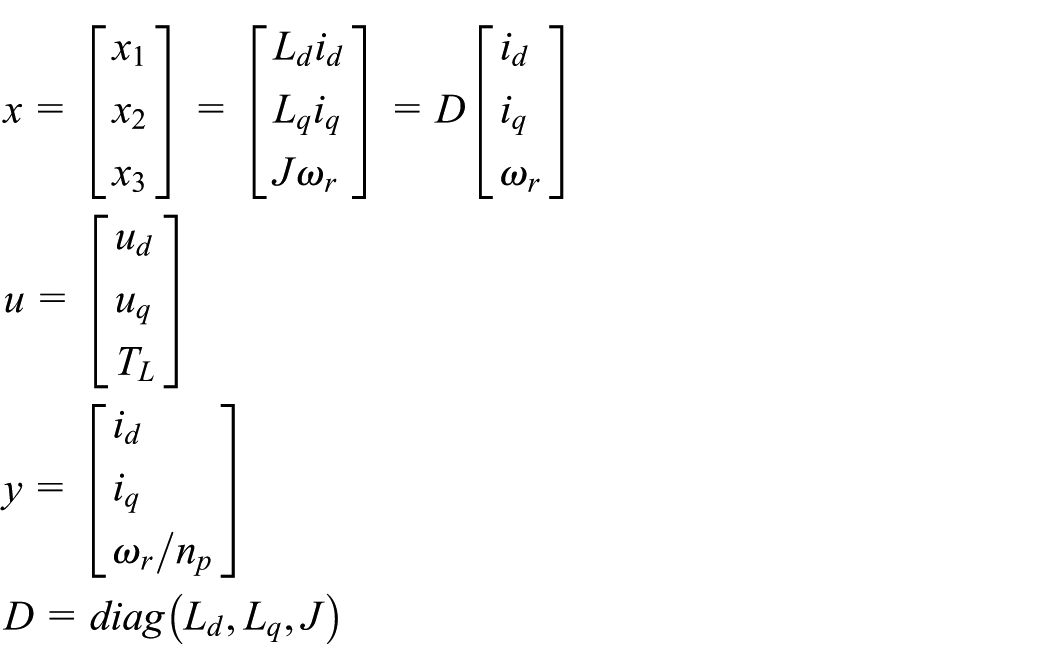
The energy of the PMSM system is given by

The PCHD model of PMSM can be obtained by formula (2), which is shown as
where
A preliminary to ADRC
ADRC systematically proposed by Han is a novel robust control method developed from nonlinear proportional–integral–derivative (PID).27,28 As illustrated in Figure 2, the conventional ADRC is composed of a tracking differentiator (TD), an extended state observer (ESO), and a nonlinear state error feedback (NLSEF) control law. The key technology of ADRC is its strong robustness, which can automatically compensate for internal and external disturbance estimations.
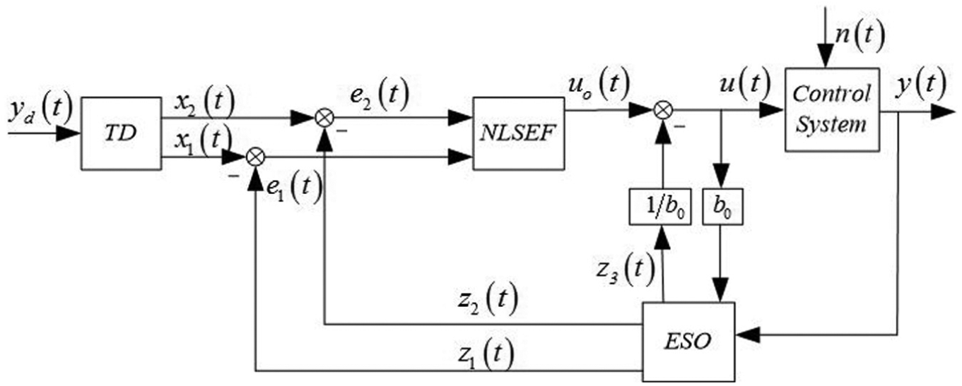
Schematic diagram of the ADRC.
Nonlinear TD
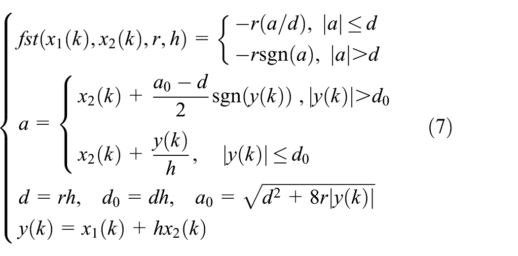
There are many advantages of TD employed in the ADRC, such as smooth regulation of tracking reference signal, rapidity and stability for tracking without overshoots, and elimination of outliers for avoiding the rapid fluctuations of the control signal. Compared to the traditional TD, the structure of nonlinear tracking differentiator (NTD) is nonlinear, and the tracking efficiency of NTD is far better than that of TD.20,28 The definition of the NTD process can be described as

where
In general, large
Extended state observer
Under the action of ESO, the ADRC can actively estimate and compensate for the effects of the unknown dynamics and disturbances in real time, so as to make an otherwise unknown plant to run like a nominal one. 29 A commonly employed third-order ESO can be built as
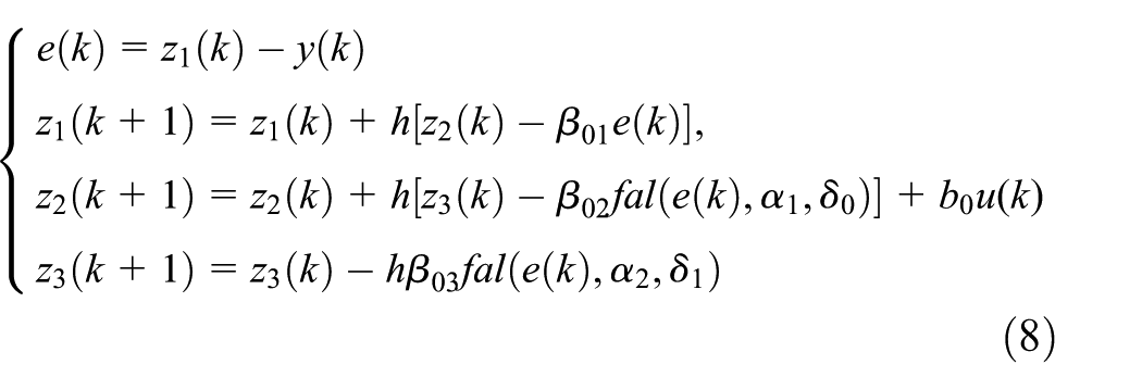
where
The nonlinear function

Under three orders,

NLSEF controller
Comparing the difference between the outputs of NTD and the outputs of ESO, the NLSEF is applied to drive the state error to zero point. The NLSEF controller is a nonlinear proportional derivative (PD) controller and can be given as
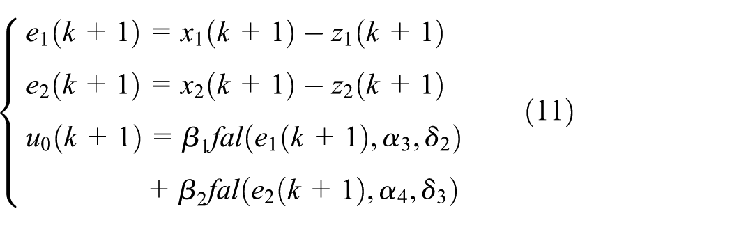
where
The PBC system of PMSM
PBC controller design
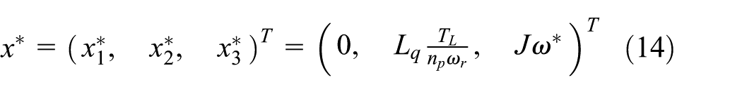
According to the principle of maximum torque per ampere (MTPA), the desired equilibrium of the PMSM system equation (3) can be acquired by

To the implicit PMSM, it is well known that
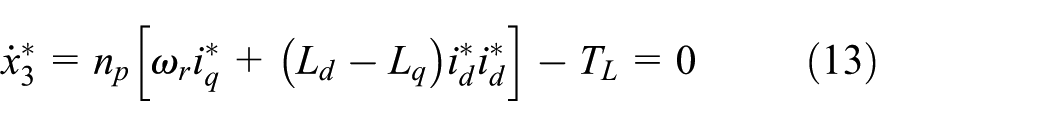
According to equation (13), when the control strategy of

by the above analysis, and the desired equilibrium of the PMSM system equation (3) can be expressed as
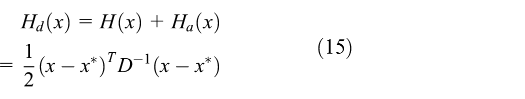
According to the desired equilibrium equation (12), the desired Hamiltonian function of the closed-loop system is built as
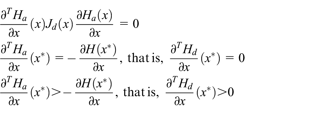
In order to satisfy the bound equation (16) at x, where x is at any location in the domain of


where
Proposition 1
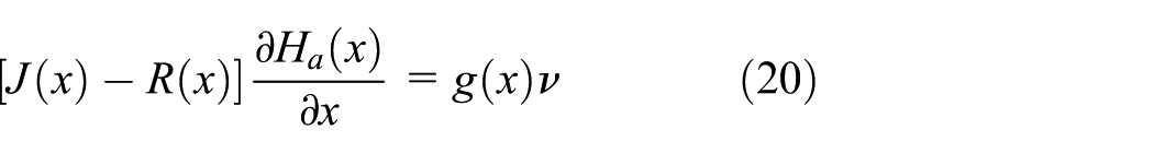
Defining v as a new input to the system equation (2) and considering the feedback, the control law is described as

For the implicit PMSM, equation (20) is satisfied as
As mentioned above, under the control of the control rule (equation (19)), the state-space function of the closed-loop system can be described as in the form of equation (21) and

According to Proposition 1, we can obtain the following:

where
In particular, we define

Through solving equation (19), the controller can be defined as

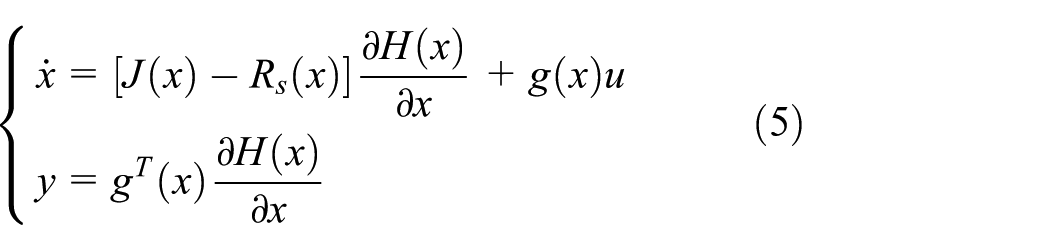
Due to the load disturbance and the unknown
According to formulas (24) and (25), the design of IDA-PBC controller is shown in the form of equation (26)

where
Stability analyses of the PBC system
According to the feedback control law (equation (17)), we can obtain

The damping matrix is defined as

By the above study, we can obtain

and the positive definition of the Hessian matrix
Therefore, the closed-loop system is asymptotically stable at equilibrium point.
The IADRC-PBC controller design
RBFNNS-IADRC control principle
The NLSEF of the traditional ADRC is optimized by the single neuron adaptive controller (SNAC). The nonlinear functions

Diagram of the IADRC-PBC.
The output of the SNAC can be calculated as

where
Adaptive updating of the proportional and derivative gains
The parameters’ adjustment goal of the RBFNNS-IADRC controller is to seek the control signal which can minimize the difference between the actual output and the desired output. The quadratic performance index of RBFNNS applied in this article for the parameter updating is defined as
With the gradient descent approach, the proportional and derivative gains

where
Its input vector is

where
With the gradient descent approach, the iterative functions for the weights of the RBFNNS are calculated as
where
The iterative functions for the node center of the RBF hidden layer is defined as

where
The iterative functions for the node width of the RBF hidden layer is defined as

where
According to the analysis above, the Jacobian matrix

Simulation result and analysis
The main selected parameters in the AC system are as follows: load converted to the motor output shaft moment of inertia:
In order to examine the control performance of IADRC-PBC for the rocket launcher system, a series of simulation was conducted using MATLAB/Simulink. The parameters in each part of the designed controller are estimated and shown as follows: the TD parameters:

Step response of load disturbance.

System dynamic response curves.
Tracking error curves of the system.
Figure 4 compares the step response of ADRC, ADRC-PBC, and IADRC-PBC controller through the position response curve added with a 300 N·m step disturbance at 3.0 s. The results of simulation data are shown in Table 1.
Step input simulation data.

ADRC: active disturbance rejection control; PBC: passivity-based control; IADRC: improved active disturbance rejection control.
As it can be seen from Figure 4 and Table 1, the ADRC step response needs a long time to adjust; when there is a load disturbance, using the ADRC algorithm in response to a large location occurs, it needs 0.37 s to recover the reference position. At the stability and rapidity, the ADRC-PBC controller relative to the ADRC controller has better improvements, but poor accuracy. However, the IADRC-PBC controller has the shortest adjustment time and the fastest response speed; when disturbed, it can reach a steady state only in need of 0.25 s. The results of experiment indicate that IADRC-PBC controller has good interference ability and better robust.
A dynamic system is shown in Figure 5 to track the location of random interference, which added to the response curve. At the stability and accuracy, when the system parameters are uncertain and external disturbances appear, the ADRC-PBC controller relative to the ADRC controller has only minor improvements. The maximum tracking error of ADRC and ADRC-PBC controller is 0.079° and 0.056°, respectively. However, at the same working condition, the IADRC-PBC controller can enable the tracking servo to reach the reference position and suppress the impact of various uncertainties rapidly by an on-line RBF neural network supervision, which is designed to on-line update the proportional and derivative gains of IADRC. The maximum tracking errors of IADRC-PBC controller is just 0.026°, with an improved tracking accuracy by 115.4% than that of the ADRC-PBC controller. The results of experiment indicate that the IADRC-PBC controller has strong anti-interference ability and good dynamic performance.
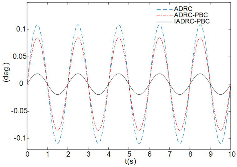
Under the control of the ADRC, ADRC-PBC, and IADRC-PBC, the tracking errors in the constant speed tracking of the system are illustrated in Figure 6. A sinusoidal disturbance is added to the constant speed reference signal, which has a frequency of 0.5 Hz and amplitude of 0.4°. After entering the steady state, the maximum tracking error of the ADRC and ADRC-PBC controller is about 0.109° and 0.085°, respectively, while that of the IADRC-PBC controller is only about 0.019°, with an improved tracking accuracy by 3.47 times than that of the ADRC-PBC controller.
By comparing step responses and constant speed tracking of the ADRC, ADRC-PBC, and IADRC-PBC controllers, it demonstrates that the IADRC-PBC controller has advantages of higher accuracy, faster response, and stronger robustness than that of ADRC and ADRC-PBC controllers.
Semi-physical simulation test
To investigate the efficiency of the proposed IADRC-PBC algorithm as a strategy in establishing a rocket launcher control system, a semi-physical simulation platform is constructed to simulate the working conditions of the position servo control system. The structure diagram of semi-physical simulation platform is shown in Figure 7. The photograph of the semi-physical simulation platform is illustrated in Figure 8. Based on the components illustrated in Figure 8, the platform is composed of seven parts, including the test bed, the control computer, the power amplifier (PA), the loading fixture (LF), the precision reduction gearbox (PRG), the actuating motor (AM), and the sensor system for measurement. The LF consists of the rotational inertia plate (RIP) and the magnetic powder brake (MPB). The function of LF is to simulate the load torque, the rotational inertia, and the frictional resistance moment of the control system. Through changing the RIP, the rotational inertia variations in the loads can be simulated well. Similarly, the frictional resistance moment and the variations in the load torque can be simulated well by controlling the output torque of the MPB.
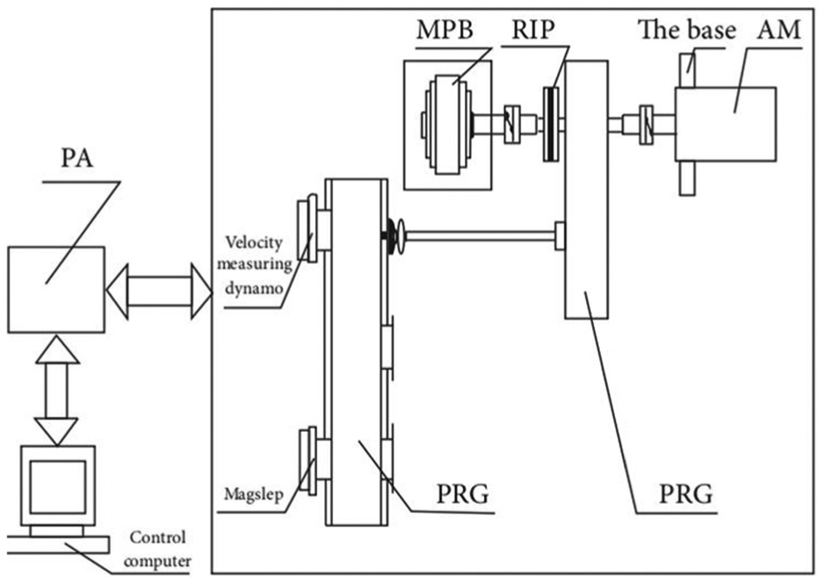
Schematic of the semi-physical simulation platform.

Photograph of the semi-physical simulation platform.
In order to verify the tracking accuracy of the position servo system with the IADRC-PBC controller, the sinusoidal command tracking with a frequency of 0.2656 Hz and amplitude of 45° is experimented on the semi-physical simulation platform. The corresponding tracking curves of ADRC, ADRC-PBC, and IADRC-PBC controllers are shown in Figure 9. From Figure 9, the maximum sinusoidal tracking error of the ADRC and ADRC-PBC controller is about 0.161° and 0.098°, respectively, while that of the IADRC-PBC control system is only about 0.054°.
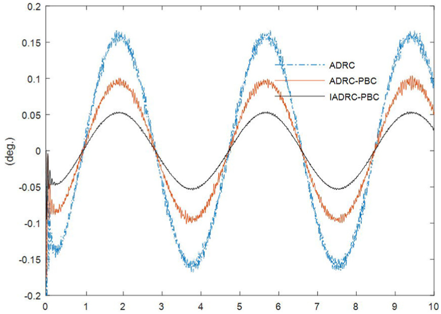
Sinusoidal tracking error curves.
On the basis of the calculation and analysis of the sinusoidal tracking errors of the ADRC, ADRC-PBC, and IADRC-PBC controller, the mean square error of the ADRC and ADRC-PBC controller is about 0.127° and 0.067°, respectively; while that of the IADRC-PBC controller is only about 0.038°, which can better meet that of the dynamic error indexes for system design requirements 0.216° or 3.6 mil (
By comparison, the IADRC-PBC controller can be able to increase the accuracy and robustness of control system effectively, which has a better steady-state and dynamic performance than that of the ADRC and ADRC-PBC controllers.
Conclusion
In this article, the IADRC-PBC control method has been proposed due to the inherent nonlinearities and the unavoidable uncertainties of the rocket launcher position servo system.
The numerical simulations show that compared with traditional ADRC controller, the RBFNNS-IADRC controller can better enhance the robustness and accuracy performance of the IADRC-PBC controller. When the step response is affected by a 300 N·m step disturbance, the maximum deviation of the IADRC-PBC controller is only about 47.2% of the ADRC-PBC controller. In terms of tracking the location of random interference, under the same working conditions, the tracking accuracy of the IADRC-PBC controller is improved by 115.4% than that of the ADRC-PBC controller. When the constant speed tracking is affected by a sinusoidal signal disturbance, the maximum tracking error of the IADRC-PBC controller is only about 19.4% of the ADRC-PBC controller.
The semi-physical simulation test results show that compared with ADRC and ADRC-PBC, the IADRC-PBC controller has a better performance of excellent dynamic and steady state. When the tracking reference is a sinusoidal signal with the frequency of 0.2656 Hz and the amplitude of 45°, the maximum sinusoidal tracking error of the IADRC-PBC controller is only about 33.5% and 55.1% of the ADRC and ADRC-PBC controllers, respectively.
From the simulation and prototype test results, it can be concluded that the IADRC-PBC controller has stronger robustness and better steady-state performance. So, it is proved that the proposed control scheme in this article is effective and suitable.
Footnotes
Handling Editor: Fakher Chaari
Declaration of conflicting interests
The author(s) declared no potential conflicts of interest with respect to the research, authorship, and/or publication of this article.
Funding
The author(s) disclosed receipt of the following financial support for the research, authorship, and/or publication of this article: The work described in this article was supported by the National Natural Science Foundation of China (51305205 and 51275245).