
Abstract
We propose an electronic differential system (EDS) based on a wavelet controller for electric vehicle with dual-wheeled-motor front drive. According to an analysis of current electronic differential strategies and vehicle driving dynamics, a new electronic differential strategy model of equal power allocation is proposed, and based on an analysis of the mathematical model of an interior permanent magnet synchronous motor, a new current controller based on the discrete wavelet transform is proposed using vector control. Based on A&D5435 hardware-in-the-loop simulation system and Carsim/Simulink, the test and simulation platform of the electric vehicle with dual-wheeled-motor front drive are established, and a vehicle performance simulation and test are performed under various driving conditions. The test and simulation results show that the equal power allocation EDS based on a wavelet controller for a front-wheel independent-drive electric vehicle proposed in this article shows excellent differential effects, stability, robustness, and vehicle handling stability.
Introduction
Electric vehicles can be divided into those with a single-power-source centralized drive and those with a multipower-source distributed drive.1–3 For the centralized drive electric vehicle, the transmission output shaft is coupled to the drive axles via the mechanical differential. 4 The mechanical differential is a necessary component of the drivetrain for the centralized drive electric vehicle because the left and right drive wheels turn at different speeds whenever the vehicle moves on the conditions of turning a corner or an uneven road. It is used in order to allow the left and right drive wheels on any one axle to rotate at different speeds.4,5 This is essential on road going vehicles as the two wheels take different paths when the vehicle goes round a corner or an uneven road, hence travel different distances and the inner wheel will rotate slower than the outer to avoid the tire wear of rigid axle.6,7 Unfortunately, excessive slipping on poor adhesion road cannot be avoided by mechanical differential. An extreme example of this occurs whenever one drive wheel is on ice and the other is on dry road. Wherever there is a large difference between the tire/road friction from left to right, the differential will tend to spin the low friction wheel. 4 In such a case with a mechanical differential, the torque transmitted by a mechanical differential will always be equal at both wheels. 4 The slipping or non-contacting wheel will receive the majority of the power (in the form of low-torque, high-rotation speed), while the contacting wheel will remain stationary with respect to the ground.4,5 Typically, the vehicle will not move in such circumstances. Therefore, in order to compensate for the shortcomings of the mechanical differential, electronic differential system (EDS) is studied. For the distributed drive electric vehicle, the EDS can not only achieve the differential speed effect of steering but also achieve the differential speed of the left and right wheels on the road with different adhesion coefficients and improve tire life and vehicle stability.7,8 So, an EDS for electric vehicle with dual-wheeled-motor front drive is studied in the article.
Referring to the domestic and foreign relevant references, Daya et al.9,10 presented an electronic differential strategy, employing a novel wavelet transform controller for two brushless DC motors to ensure driving left and right rear driving wheels. The ideal Ackermann steering model is used in the rotational speed distribution of the left and right wheels. The motor control adopts the speed input, and the control object is a permanent magnet brushless DC motor. Ozkop et al. 11 presented an EDS with a fuzzy logic sliding mode controller for direct driving electric vehicle and using the Ackermann–Jeantaud steering model, speed, and the angular position of the steering wheel obtained the left and right wheel actual reference speeds. Munusamy and Weigl 12 presented a torque vectoring algorithm based on Ackermann steering geometry and changed the speed of the two rear driving wheels when vehicle is cornering. They analyzed the relationship between different cornering radius and vehicle speed under the three steer characteristics of neutralsteer, understeer, and oversteer. Madaras et al. 13 discussed the possibilities for the simulation of the driving dynamics of an electric vehicle during cornering. Among them, in the research process of vehicle dynamics steering model, each wheel drew a circle with a common center. Hartani et al. 14 presented an electronic differential control strategy based on the direct torque fuzzy control, by which the upper motor demand speed is obtained through the ideal Ackermann steering model. Yin et al. 15 analyzed the mechanism of the relationship between feedback gain and steering characteristics of a four-wheel drive electric vehicle EDS based on Ackermann steering kinematic model. The results show that the EDS feedback gain plays an important role in its control performance, especially the steering characteristic. Haddoun et al. 5 presented the design and implementation of an electric differential based on the principle of mechanical differential, and the electric differential system control performances are validated under New European Driving Cycle. From the simulation results, we can see that the paper achieves the equal torque control strategy when driving on the ideal level pavement. Folgado et al. 6 considered that the principle of a mechanical differential proposed an electronic differential control strategy based on equal torque control for an electric vehicle with rear wheel individual drive. Chen et al. 16 presented the integrated control of electronic differentials with active front steering in order to improve vehicle steering dynamics and an asymptotic decoupling feedback control law based on a second-order vehicle model. Differential torques approaching zero is achieved during steering. Gasbaoui and Nasri 17 presented a four-wheel drive electric vehicle controlled with direct torque control–based space vector modulation. The speed of four wheels is calculated independently during the turning based on equal torque allocation strategy. Under the acceleration and steering condition, Nasri and Gasbaoui 18 presented a novel speed control design of four-wheel drive electric vehicle to improve the comportment and stability based on intelligent adaptive fuzzy proportional integral (PI) controller. Among them, the equal torque control allocation strategy is adopted for the left and right wheels during steering. Hua et al. 19 studied the differential steering control technology of rear wheel–independent driving electric vehicle based on the high-speed steering characteristic and considering the yaw moment. Jang et al. 20 proposed a dynamic curvature controller by applying the dynamic curvature of the path, derived from vehicle dynamic state variables: yaw rate, side slip angle, and speed of a vehicle based on direct yaw moment control and wheel longitudinal slip control for four-wheel independent drive electric vehicles. Kobayashi et al. 21 constructed new formulae of the mechanism by which direct yaw moment alters the cornering resistance and mechanical power of all wheels based on a simple bicycle model, and these formulation results were validated by an actual test vehicle equipped with in-wheel motors in steady-state turning. For low adhesion coefficient pavement, Long and Li 22 presented an electronic differential control strategy based on equal adhesion coefficient, it makes electric vehicle (EV) with two dual-motorized wheels achieve differential by distributing and controlling the driving torque. Jalali et al. 23 presented a new method to control the lateral stability of the distributed drive electric vehicles. A model predictive control technique is used to track the desired vehicle yaw rate while maintaining small lateral velocity and tire slip ratios.
From the analysis of the references, the electronic differential control strategy mainly includes the following three types: (1) literature9–15 mainly shows the difference speed control of the left wheel and right wheel when steering based on the ideal Ackermann steering model. However, when the vehicle’s steering is disturbed by external environment and the uneven road, the ideal Ackermann steering model will fail. At the same time, the ideal Ackermann steering model is a static geometric model. It does not consider the influence of centrifugal force, wheel radius, tire deformation, uneven road, and other factors on the model when it is steering at a high speed and large angle. It is an ideal static model, so it has some limitations. And these literatures only studied the steering of the ideal ordinary pavement and did not study the adaptability under the uneven road condition and the road condition of the adhesion coefficient mutation. (2) Literature5,6,16–18 mainly shows the different speed control of the left wheel and right wheel when steering based on the equal torque allocation control strategy. The equal torque allocation electronic differential control strategy has a certain advantage on the road with good adhesion coefficient. However, when the left and right wheels run on roads with different adhesion coefficients, due to the equal torque allocation, the wheels on the road with low adhesion coefficient will have serious spin phenomenon. As the wheel rotation speed increases, the wheel on the low adhesion coefficient road will consume most of the power, which will affect the normal driving of the vehicle and affect the stability and safety of the vehicle seriously. Therefore, the equal torque allocation electronic differential control strategy only adapts to the differential steering on the road with good adhesion coefficient and the driving performance of the bisectional roads with lower adhesion coefficient is poor. (3) Literature19–23 mainly study on driving force control strategy of distributed driving electric vehicle steering based on vehicle handling stability parameters, such as yaw moment, slip rate, and yaw rate. Although these vehicle handling stability parameters can well characterize the stability of distributed driving electric vehicle steering or driving on low adhesion road, avoid the non-steady state of the vehicle. However, these handling stability parameters are difficult to measure and estimate accurately. At the same time, only under the extreme driving conditions, these handling stability parameters change significantly, and these handling stability parameters are characterization parameters after the vehicle has been in an unstable condition. But, when driving on normal road, these handling stability parameters do not change much. Therefore, the driving control strategy of distributed driving electric vehicle based on vehicle handling stability parameters is more suitable for extreme conditions. However, the control effect under good driving condition needs to be further verified. Therefore, based on the advantages and disadvantages of the above three electronic differential control strategies, the article proposes an electronic differential control strategy based on equal power allocation for front-wheel-independent driving electric vehicle. The control strategy can not only achieve the steering differential control effect on a good road but also prevent the wheel from spin and achieve differential control on the bisectional road with lower adhesion coefficient.
Meanwhile, the interior permanent magnet synchronous motor (IPMSM) with magnets buried in the rotor core offers excellent capabilities such as high efficiency, high reluctance torque, a mechanically robust rotor, and a small effective air gap.24–26 Therefore, the IPMSM is widely used in high-performance drives for electric vehicles, aerospace, and robots. 25 Using the Clark transformation and Park transformation, the stator current is transformed into the excitation current and torque current, and thus vector control is achieved to transform the three-phase AC magnetic field system into the DC magnetic field system. A similar DC motor control performance can be obtained by independent control of the IPMSM excitation current and torque current. 24
The traditional PI and proportional–integral–derivative (PID) current controllers are widely applied in vector control. However, the performances of the PI and PID current controllers are easily affected by parameter variations, noise, temperature, and unknown load dynamics. Moreover, the controller parameters are challenging to design if an accurate model of the system is not available.25,27 In order to overcome the problems of PI and PID controllers, some adaptive controllers have been developed, such as model reference adaptive controller, sliding mode controller, variable structure controller, self-tuning regulator, and artificial intelligence controllers. 24 The performance of these controllers is related to motor parameters. 24 Therefore, the performance of IPMSM using approximate model parameters is not satisfactory for different operating conditions.24,25 The wavelet transform can simultaneously decompose the steady-state and the unsteady-state, periodic, and aperiodic signals into the time domain and frequency domain.24,25,28 Relative to the traditional PI, PID, and other adaptive intelligent controllers, the wavelet controller has the advantages of not requiring a precise system mathematical model, the ability to address a wide range of nonlinear functions with the desired degree of accuracy and conditions, and a foundation based on the filter bank structure of the orthogonal wavelet and scaling functions.25,28 As a result, many traditional PI and PID controllers have been replaced by the wavelet controller.9,10,24–32 The EDS of the electric vehicle based on the wavelet controller has been described previously.9,10 For example, in the literature,24,27 a speed controller based on the wavelet neural network is proposed for the IPMSM. Researchers have also proposed a hybrid neuro-wavelet scheme for online tuning of a wavelet-based multi-resolution proportional integral derivative (MRPID) speed controller for the IPMSM. 25 In addition, a speed controller based on MRPID has been designed for the IPMSM, 26 and in the literature, 28 a temperature controller based on MRPID is proposed for the ambient air temperature of a hybrid vehicle battery energy storage system. In the literature, 29 a speed controller based on MRPID is proposed for a brushless DC motor, and in the literature,30–32 a speed controller based on the wavelet transform and fuzzy logic tuning is described for an induction motor.
Therefore, to address the insufficiency of the three basic types of electronic differential strategies in combination with the advantages of the wavelet controller, we propose an equal power allocation EDS based on a wavelet controller for a front-wheel independent-drive electric vehicle. First, based on an analysis of the electronic differential fundamental, a new electronic differential strategy of equal power allocation is proposed. Second, a new current controller based on the discrete wavelet transform (DWT) is proposed for the IPMSM in vector control. Finally, Carsim/Simulink co-simulation platform and front-wheel independent-drive vehicle hardware-in-the-loop simulation system based on A&D5435 are established. The driving performance of the electronic differential control system is analyzed and simulated under different driving conditions.
Electronic differential strategy model
Electronic differential analysis
As shown in Figure 1, the rolling distance S1 of the wheel and the driving distance S2 of the wheel center plane fixed to the vehicle body can be expressed as

where w is the wheel rotation speed in r/min, R is the wheel rolling radius in meters, and v is the velocity of the wheel center fixed to the vehicle body in km/h.
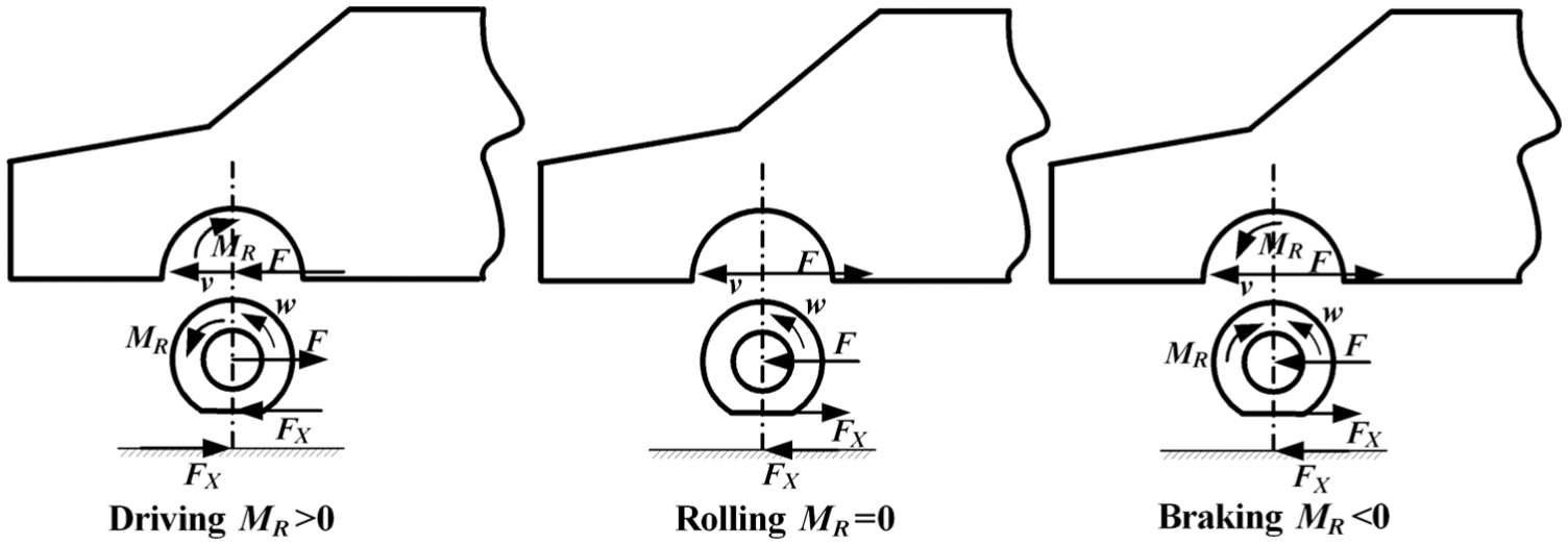
Forces of vehicle body, wheels and ground (ignoring vertical force action).
When the wheel is skidding, S1 is larger than S2. When the wheel is rolling purely, S1 is equal to S2. When the wheel is locked, S1 is smaller than S2. Because of the elastic rubber tire operating characteristics, the wheel also has a certain slip or skid characteristic while the vehicle is normally driving or braking. However, when the difference between S1 and S2 is large, an excessive uncoordinated phenomenon arises that causes large slip or skid of the wheels. As a result, the vehicle cannot drive normally, and the tire life and stability are reduced. Therefore, in order to solve slip or skid problem of the wheels of distributed electric vehicles in turning or driving on different adhesion coefficient roads, the electronic differential control strategy of the front-wheel-independent drive electric vehicles is researched in the article.33–35
Electronic differential strategy model of equal power allocation for the drive wheels
The forces of the vehicle body, wheels, and ground (ignoring the vertical force action) are shown in Figure 1. The wheel driving dynamics equation can be expressed as

where I is the wheel moment of inertia in kg m2, MR is the wheel drive torque in Nm, Mwheel is the wheel quality in kg, F is the force between the wheel and the body in N, and FX is the road-tire tangential force in N.
According to equation (2), if no coordination exists between the wheel rotation speed w and the wheel center velocity fixed to the vehicle body v, the interaction force F is produced to adaptively control the wheel rotation speed. The interaction force F will cause a yawing moment applied to the vehicle mass center position. Therefore, in order to reduce or eliminate the yaw moment applied to the vehicle mass center caused by the incoordination of the vehicle speed and the wheel rotate speed, this article also takes into account that the equal torque allocation electronic differential control strategy of distributed drive electric vehicle cannot solve the spin problem of low adhesion coefficient pavement. So, a new equal power allocation electronic differential control strategy for front-wheel-independent drive electric vehicles is proposed, the principle shown in Figure 2.

Electronic differential strategy of equal power allocation.
First, the electronic differential strategy of equal power allocation equally distributes the driver demand torque T. Second, according to the feedback speed (w1 and w2) of the left and right drive motors and the initial average distribution torque T/2, the demand power P1 and P2 of the left and right drive motor are calculated, respectively. Finally, according to the principle of equal power allocation for drive motors and based on the average distribution of power (P1 + P2)/2 and the real-time feedback motor speeds (w1 and w2), the torque of the left and right drive motor is adjusted under the constraint of the driver demand torque T. The calculation method used to output the actual demand torque T1 and T2 of the drive motors is shown in equations (3) and (4) below


Design of the electronic differential system based on a wavelet controller
We propose an equal power allocation EDS based on a wavelet controller for a front-wheel-independent drive electric vehicle, as shown in Figure 3. The control system is composed of two parts. The upper part is the vehicle controller unit (VCU) based on equal power allocation, and the lower part is motor control unit (MCU) based on wavelet controller. Driver operating information (namely, the steering angle, brake pedal position, and accelerator pedal position) and wheel speed information are collected in VCU, and according to the driver demanded, the torque analysis method is applied to obtain the driver demand torque T. According to the electronic differential strategy of equal power allocation and the wheel speed, the demanded torque of the left and right drive motor (T1 and T2) is obtained. For MCU, according to T1 and T2, IPMSM drive control is achieved by vector control of the current loop based on the wavelet controller and space vector pulse width modulation (SVPWM) technology. Torque is transmitted to drive wheels via the single stage reducer. At the same time, wheels speed signals from MCU are transmitted to vehicle control unit.

Structure of the electronic differential system.
IPMSM vector control strategy based on a wavelet controller
IPMSM dynamics
Under the two-phase rotating (d-q) coordinate system, the voltage equation of the IPMSM can be expressed as
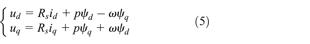
where
Because the rotor flux of the IPMSM is constant, the flux linkage equation in the d-q coordinate system is

where
The electromagnetic torque equation and the motor motion equation can be expressed as

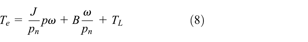
where J is the moment of inertia of the motor and load, B is the damping coefficient of the motor, TL is the load torque, and Pn is the number of pole pairs.
In general, the d-axis current (id) is typically set to zero in the IPMSM drive control strategy, where the IPMSM reluctance torque is zero. However, in the IPMSM, the q-axis inductance is greater than the d-axis inductance. To effectively use the reluctance torque, maximum torque current ratio control (MTPA) is used in the IPMSM below the rated speed, and the d-axis current (id) is designed as 24

Substituting equation (9) into equation (7), the nonlinear relationship between the q-axis current iq and the electromagnetic torque Te is obtained as 27

Field weakening (FW) control is applied above the rated speed for the IPMSM. After ignoring the voltage drop across the stator resistance, the d-axis current id is obtained as 24

where

where
The basic schematic of the IPMSM using MTPA and FW is shown in Figure 4. The motor controller receives the motor-demanded torque

Schematic of vector control of IPMSM.
Currently, the d-axis and q-axis current controllers are generally based on traditional PI and PID controllers, but PI and PID current controllers are easily affected by parameter variations, noise, temperature, and unknown load dynamics.25,27 Moreover, the controller parameters are challenging to design if an accurate model of the system is not available. Certain adaptive controllers have been developed to overcome the problems of PI and PID controllers, such as the model reference adaptive controller, sliding mode controller, variable structure controller, self-tuning regulator, and artificial intelligence controllers. These controllers are typically based on system model parameters. 24 Selected strict conditions and a priori knowledge of the controlled system are typically required before designing these controllers.25,26 Relative to the traditional PI, PID controller, and other adaptive intelligent controllers, the wavelet controller has the advantages of independence from a precise system mathematical model, the ability to address a wide range of nonlinear functions with the desired degree of accuracy and conditions, and a foundation based on the filter bank structure of orthogonal wavelet and scaling functions.27,28 Therefore, the application of the wavelet controller in the IPMSM drive control is increasingly extensive, and the current controller for the IPMSM in this article uses the current controller of the DWT.
DWT and multi-resolution analysis
The wavelet transform is an effective mathematical analysis tool that decomposes the data, function, or operator into different frequency components and uses the decomposition method to study the components of the corresponding scale. 36 This approach is an extension of the Fourier transform, which can simultaneously analyze the time-domain and frequency-domain information of the signal. 31 The DWT of the signal f(t) is defined as

where
To ensure consistency of analysis between the original signal domain and the transform domain, the original signal f(t) can be reconstructed completely using

In general, it is challenging to construct an orthogonal wavelet. However, in 1986, Mallat and Meyer constructed the formula of multi-resolution analysis (MRA), which solves the problem of orthogonal wavelet construction. MRA is a convenient framework for hierarchical representation of functions or signals on different scales. 29 The goal of MRA is to develop representations of a signal f(t) using its orthonormal bases, which are the scale function space and wavelet function space. The scale function space represents the low-frequency information of the signal, and the wavelet function space represents the high-frequency information of the signal. A mixed-form N-level discrete wavelet series representation of the signal f(t) is defined as 29

where


where
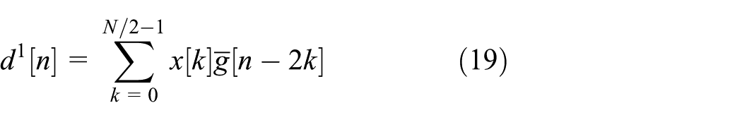
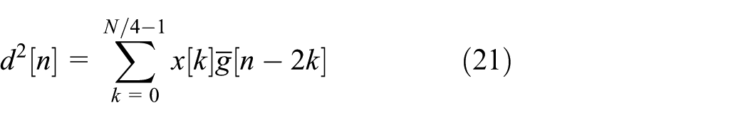
The DWT can be achieved by cascaded stages of low-pass and high-pass filters followed by down sampling. The DWT of second-level decomposition is shown in Figure 5 for the discrete current error signal x ={x[0], x[1], …, x[N – 1]}= c0, whose length is N. The discrete current error signal passes through the low-pass filter and the two down sampling operations, and thus the approximation coefficients c1 of the first-level decomposition can be obtained. In addition, by passing through the high-pass filter and two down sampling operations, the detailed coefficients d1 of the first-level decomposition can be obtained. The coefficients c1 and d1 can be mathematically represented as25,26,31,36


Schematic of the DWT two-level decomposition algorithm.
The approximation coefficients c1 of the first-level decomposition continue to pass through the cascaded stages of the low-pass and high-pass filters followed by two down sampling. The approximation coefficients c2 and the detailed coefficients d2 at second-level decomposition can be obtained and are mathematically represented as25,26,31,36

This decomposition process can be continued until the desired decomposition level is reached. After the S-level decomposition of the discrete signal x, a set of these signals at different scales (frequencies) can be obtained and are expressed as 29

where
In traditional PID control, the gain KP acts on the current error, the gain KI acts on the integral of current error and the gain KD acts on the derivative of current error; thus, the proportional error, integral error, and derivative error can be obtained, respectively. In terms of the frequency information of the error signal, the proportional and integral terms tend to capture the low-frequency information of the error signal, and the derivative captures the high-frequency information of the error signal. 29 However, the DWT of the error signal also results in mixed-frequency information regarding the error signal. Therefore, according to the frequency information equivalent principle of the two methods, as shown in Figure 6, the d-axis and q-axis current controllers based on the DWT are defined as

where ilref is the target current, il is the actual current, el is the current error signal, vlref is the output of current controller,

Current controller based on the DWT.
Selection of decomposition level and wavelet function
In the process of implementing the current controller based on the DWT, it is necessary to carefully select the wavelet function type and decomposition level. 25 The decomposition level determines the number of gain parameters of the wavelet controller. According to the Shannon entropy criterion, the optimal decomposition level of the DWT can be selected.9,10,25,37 The entropy of the discrete current error signal x = x[n]={x[0], x[1], …, x[N – 1]} is defined as

According to equation (24), the signal entropy of each level is calculated. If the signal entropy H(x) p at the p-level decomposition is greater than or equal to the signal entropy value H(x)p – 1 at the (p – 1)-level decomposition, then the entropy can be represented as

At this time, the optimal decomposition level of the DWT is p – 1 for the current error signal.
The performance of the controller varies for different types of wavelet functions used in the wavelet controller. 29 The choice of the best wavelet function in the wavelet controller depends on the application requirements and the signal characteristics. 26 The ideal properties of the wavelet function are compactness, orthogonality, linear phase, and low approximation error, among others. 31 The optimal wavelet functions and the number of optimal retained decomposition coefficients can be selected according to the minimum description length (MDL) criterion.25,32,37,38
We assume that the wavelet function library is B ={B1, B2, …, BM}, and based on the wavelet function Bn in the wavelet function library, the signal f can be expressed as

where Wn is the orthogonal matrix whose column vectors are the basis elements of Bn and
In terms of data compression, the value of k should be as small as possible, but to reduce the difference between the estimated signal and the real signal, the value of k should be as large as possible, and the MDL criterion can effectively resolve this contradiction. 38 The MDL function is defined as10,37,38
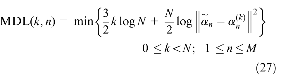
where N is the length of the signal, M is the total number of wavelet functions in the wavelet function library, k is the number of non-zero coefficients of the wavelet expansion coefficient vector of signal f, n is the number of wavelet function in the wavelet library,
The first term of the MDL function is a penalty function that increases linearly with the number of the retained wavelet decomposition coefficient k. The second term describes the logarithmic of residual energy between
The d/q-axis current controller based on the DWT
Based on the d-axis and q-axis discrete current error signals, a wavelet function library of M = 22 is constructed, including 10 wavelets in the Daubechies family, 5 wavelets in Coiflets, and 7 wavelets in Symlets. First, according to the Shannon entropy criterion, the optimal decomposition level of the current error signal is selected under different wavelet functions. A larger decomposition level is correlated with a larger processor overload. In this study, to reduce processor overload and operation time, the decomposition level of the d-axis and q-axis discrete current error signals is set to 2.
The optimal wavelet function is selected based on the MDL criterion, for example, the results of the MDL function based on Coiflets5 is shown in Figure 7. The function reaches the minimum value of −631.1 at k = 3.

MDL function based on Coiflets5.
This process is repeated until the last wavelet function in the library is reached, and the optimal wavelet function “db4” is selected. The d-axis and q-axis current controllers based on the DWT are constructed as


In the motor drive system, the current command and the system disturbance are the low-frequency signals. Increasing the gain parameter of the low-frequency signal can improve the anti-disturbance ability of the system. The gain parameter of the medium-frequency signal increases the damping of the system and this increase improves the system’s transient and steady-state response. The sensor noises compose the high-frequency signal, and the noises can be reduced by reducing the high gain parameter of the high-frequency signal. 25
Establishment of co-simulation platform and hardware-in-the-loop simulation system
To verify the performance of the equal power allocation EDS based on the wavelet controller, co-simulation platform of an independent-drive electric vehicle based on Carsim/Simulink and the front-wheel-independent drive electric vehicle test platform based on A&D5435 hardware-in-the-loop simulation system are established, respectively.
Co-simulation platform of an independent-drive electric vehicle based on Carsim/Simulink
As shown in Figure 8, the co-simulation platform for an electric vehicle with a dual-wheeled-motor front drive was established. Because Carsim contains the complete driver model and driving environment model, this article uses Carsim driver model.

Co-simulation platform for electric vehicle with a dual-wheeled-motor front drive.
The premise of implementing the co-simulation is to correctly configure the parameters of the Carsim input and output interfaces. The input and output interface parameters of this article are shown in Table 1.
Parameters configuration of Carsim input and output interface.

The front-wheel independent-drive electric vehicle test platform based on A&D5435 hardware-in-the-loop simulation system
In this article, on the basis of the front-wheel-independent drive electric test vehicle, using A&D5435 hardware-in-the-loop simulation system and MATLAB/Simulink code automatic generation technology, the front-wheel-independent drive electric vehicle test platform is set up to verify the EDS based on a wavelet controller, shown in Figure 9. Based on the Real-Time Workshop technology of MATLAB/Simulink, the electronic differential control strategy model based on equal power allocation and the vector control strategy model of IPMSM based on a wavelet controller is compiled and downloaded to A&D5435. The hardware system of the front-wheel-independent drive electric vehicle test platform based on A&D5435 hardware-in-the-loop simulation system, as shown in Figure 10. The A&D5435 virtual controller is used to replace the electric vehicle controller, the virtual controller input signals include steering wheel angle, accelerator pedal opening, vehicle attitude, vehicle speed, motor rotate speed, motor torque, and so on. The control system calculates left and right wheel motor driving torque based on the collected signal and equal power allocation control strategy and transmits the required torque to the motor controller. The steering wheel angle signal is collected by the CMSWB torque and speed sensor of the Kistler company, the accelerator pedal opening signal is collected by the PASST B5 pedal potentiometer, and the speed signal is collected by the VGPSVBOX 3I speed sensor of the Racelogic company. The vehicle attitude signal is collected by the RT3100 inertial navigation of Oxford Tech, and the motor speed and torque signal are collected by the motor controller. And considering the difference in the type of sensor output signal, the steering wheel angle signal and the accelerator pedal opening signal are input through the I/O port, but the speed signal, the vehicle attitude signal, and the motor signal are transmitted through the CAN bus. At the same time, considering the difference between the vehicle dynamics simulation model of Carsim and test vehicle, the key parameters for the test vehicle in Carsim software such as vehicle wheelbase, wheel track, position of the mass center, steering system transmission ratio, wheel radius, and other key parameters were adjusted to obtain consistent control effect.

The front-wheel independent-drive electric vehicle test platform.
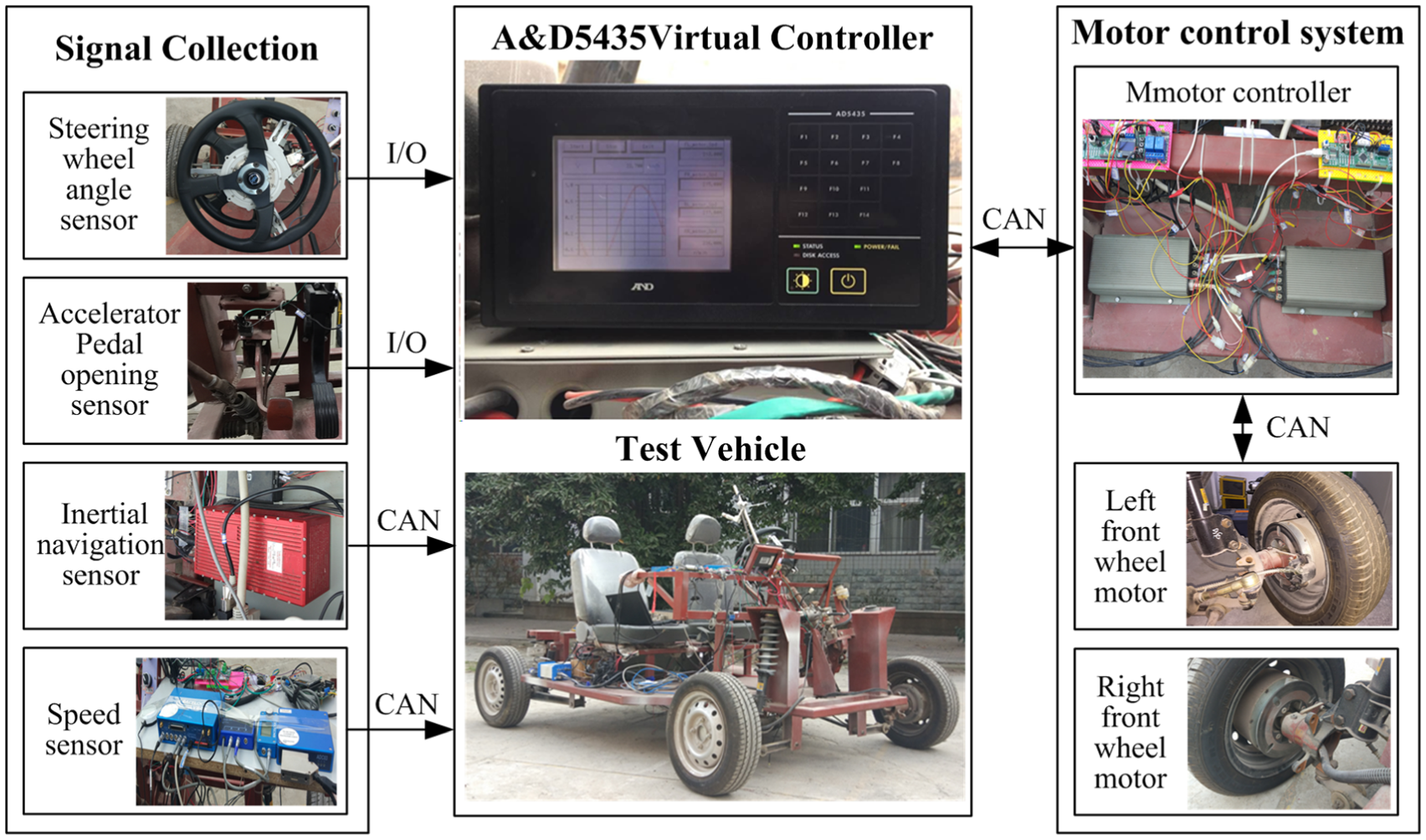
The hardware system of electric vehicle test platform.
Simulation and experiment analysis
To verify the performance of the equal power allocation EDS based on the wavelet controller, the simulation and experiment of the front-wheel-independent drive electric vehicle is conducted under different driving conditions. First, in order to verify stability, real-time and tacking characteristic of the vector control strategy of IPMSM is based on the wavelet controller. The simulation test of torque following characteristics under the accelerator pedal continuous step input condition and steering wheel with large angle input and steering wheel aligning condition are carried out. Moreover, the proposed IPMSM control strategy based on wavelet controller is compared with the traditional PID and fuzzy PID control strategy. Then, in order to verify the stability, responsiveness, and robustness of the proposed equal power allocation electronic differential control strategy under the driving conditions of sudden disturbance such as steering wheel angle step input, sudden change of road surface roughness, and abrupt change of road surface adhesion coefficient. Under the Carsim/Simulink Co-simulation environment, the three kinds of extreme simulation conditions of wheels with large rotation speed difference and the driving conditions sudden disturbance are designed. They are the steering driving condition under the big steering angle input, the straight driving condition on the uneven road, and the straight accelerate driving condition of the on bisectional road. At the same time, the equal power allocation electronic differential control strategy proposed in this article is compared with the equal torque allocation electronic differential control strategy and the centralized drive vehicle that uses the viscous limited-slip mechanical differential. Finally, real road test was carried out based on the front-wheel independent drive vehicle hardware-in-the-loop simulation system.
Simulation analysis of motor control system based on the wavelet controller
In order to verify stability, real-time and tacking characteristic of the vector control strategy of IPMSM is based on the wavelet controller. The paper researches on torque following characteristics under the accelerator pedal continuous step input condition and steering wheel with large angle input and steering wheel aligning condition. At the same time, in order to verify the advanced nature of the wavelet controller, the traditional PID control strategy and fuzzy PID control strategy are compared and analyzed under the two conditions.
The accelerator pedal continuous step input condition
The simulation curve is shown in Figure 11 for the case in which the accelerator pedal is a continuous step input. The control signal of the simulation is the accelerator pedal opening, as shown in Figure 11(a). The simulation results comparison is shown in Table 2. In the simulation process, the target torques of the left and right wheels are the same, and the step to 169.95 N m (30% opening) occurs at 0.1 s, followed by the 0.5 s step to 281.75 N m (50% opening). Figure 11(b) shows the enlarge simulation curves of drive wheel torque at 0.1 s for three different control strategies. Figure 11(c) shows the enlarge simulation curves of drive wheel torque at 0.5 s for three different control strategies. Relative to the IPMSM control system using the PID and Fuzzy PID at the accelerator pedal continuous step input condition, the wavelet controller strategy is adopted, the torque overshoot is smallest and takes least time to reach steady state. Therefore, under the accelerator pedal continuous step input condition, vector control strategy of IPMSM based on the wavelet controller has the best stability, real-time and tacking characteristic.

Simulation comparison of continuous step accelerator pedal input (a) accelerator pedal opening signal, (b) enlargement of drive wheel torque at 0.1 s, and (c) enlargement of drive wheel torque at 0.5 s.
Simulation results comparison of the accelerator pedal step input condition.

PID: proportional–integral–derivative; FUZZY: fuzzy PID; WT: wavelet transform.
The steering wheel step input and aligning condition
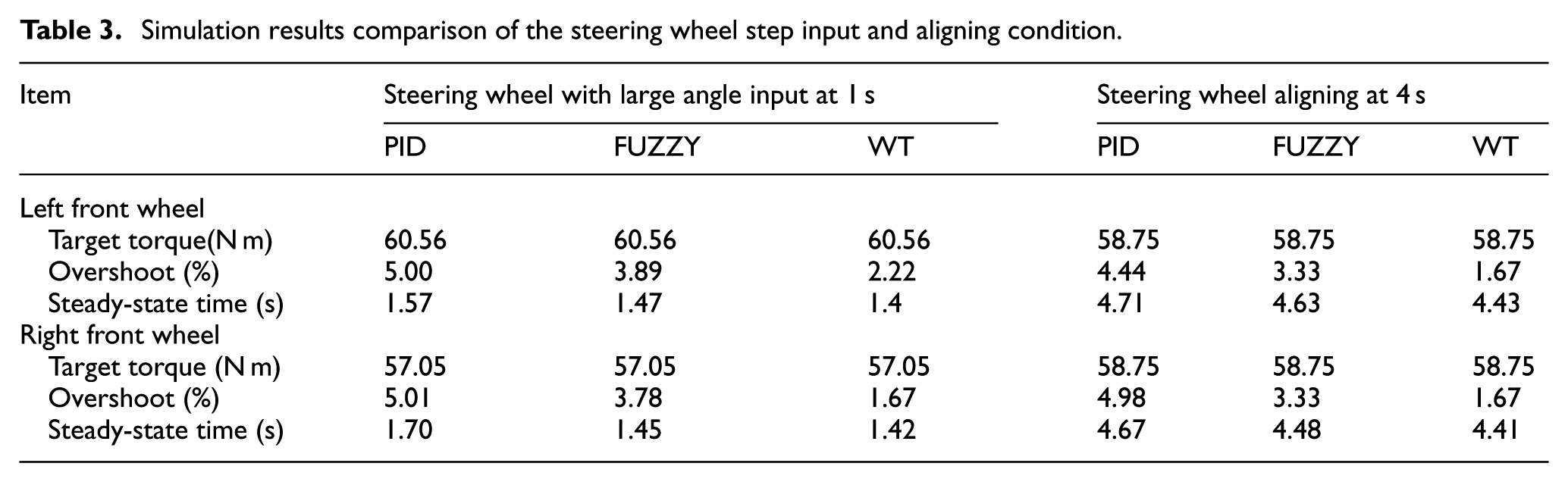
The simulation curve is shown in Figure 12 for the case in which the steering wheel has large angle input and steering wheel aligning condition. The simulation results comparison is shown in Table 3. The left and right wheels target torque is shown in Figure 12(a). In the process of simulation, the vehicle running in a straight line at the beginning, and the torque of the left and right wheels is equal (58.75 N m). At 0.1 s moment, the steering wheel input a large angle, the torque of the inner wheel step to 60.56 N m, and the torque of the outer wheel step to 57.05 N m. At 0.4 s moment, the steering wheel back to the initial position, the inner and outer wheel target torque back to 58.75 N m. Figure 12(b) shows the simulation curves of the left and right wheel target torque and actual torque for three different control strategies under the steering wheel with large angle input and steering wheel aligning condition. Figure 12(c) is the convergence curve of error value of the actual torque and the target torque under the wavelet control strategy. The simulation results illustrate that under the steering wheel with large angle input and steering wheel aligning condition, relative to the IPMSM control system using the PID and Fuzzy PID, the wavelet control strategy is adopted, the torque overshoot is smallest and takes least time to reach steady state. Therefore, under the steering wheel with large angle input and steering wheel aligning condition, vector control strategy of IPMSM based on the wavelet controller has the best stability, real-time and tacking characteristic.

Simulation comparison of the steering wheel step input and aligning condition (a) the target torque of the left and right wheel, (b) the actual torque of the three control strategies, and (c) the convergence curve of error value under the wavelet control strategy.
Simulation results comparison of the steering wheel step input and aligning condition.
By comparison of simulation results, under the accelerator pedal continuous step input condition and the steering wheel with large angle input and steering wheel aligning condition, relative to the IPMSM control system using the PID and Fuzzy PID, the wavelet control strategy exhibits smallest torque overshoot and fastest torque response. The excellent control effect of the IPMSM control system based on the wavelet controller provides an effective guarantee for the implementation of the equal power allocation electronic differential control strategy.
Steering driving condition
In order to verify the advantages and disadvantages in terms of steering performance and vehicle stability of the equal power allocation electronic differential control strategy under steering driving condition, compared with equal torque allocation and the centralized drive vehicle that uses the viscous limited-slip mechanical differential, the simulation conditions are set according to the steering driving condition. At the same time, the characteristics of the viscous limited-slip mechanical differential are set. Viscous limited-slip mechanical differential is a type of differential that allows its two output shafts to rotate at different speeds but limits the maximum difference between the two shafts. And according to the characteristics of viscous limited-slip mechanical differential set the limit value of the speed difference, the vehicle steering stability is studied when the vehicle with the viscous limited-slip mechanical differential reaches the limit value of the speed difference and does not reach the limit value of the speed difference, to verify the control effect of the control strategy and the steering stability of the vehicle.
The simulation curves are shown in Figure 13 when the accelerator pedal is 20% and the steering wheel is a step input with an initial speed 20 km/h. The control signal of the simulation is the accelerator pedal opening and steering angle, as shown in Figure 13(a) and (b). The simulation curves of the drive wheel torque are shown in Figure 13(c). The simulation curves of the drive wheel slip rate are shown in Figure 13(d). The simulation curves of vehicle lateral acceleration are shown in Figure 13(e). The simulation curves of vehicle yaw velocity are shown in Figure 13(f). Table 4 shows the maximum value of the simulation results. Comparing the simulation results of equal power allocation electronic differential control strategy proposed in paper, equal torque electronic differential control strategy as well as the centralized drive vehicle with the viscous limited-slip mechanical differential when it reaches the limit value of the speed difference and does not reach the limit value of the speed difference. Simulation results including torque, slip ratio, yaw rate, and lateral acceleration are as follows:
The torque of the left and right drive wheel always maintained at 115.26 N m for the distributed drive vehicle with the electronic differential strategy of equal torque allocation. However, for the distributed drive vehicle with the electronic differential strategy of equal power allocation, the torque of the left and right drive wheel has an unequal distribution, the torque of the left drive wheel is 115.68 N m, whereas the torque of the right drive wheel is 114.84 N m. The torque difference between the left and right wheel is small (0.84 N m). It is because that turning radius is much larger than the wheel track when the vehicle turns, so the wheel speed difference between the left and right wheels is not large and the torque difference is small for the distributed drive vehicle with the electronic differential strategy of equal power allocation. When the centralized drive vehicle with the viscous limited-slip mechanical differential does not reach the limit value of the speed difference under steering driving condition, the torque difference between the left and right wheel (left 117.94/ right 112.58) is larger (5.36 N m). Especially when the vehicle with the viscous limited-slip mechanical differential reaches the limit value of the speed difference under steering driving condition, the torque difference between the left and right wheel (left 125.93/ right 104.59) is largest (21.34 N m).
For the centralized drive vehicle with a viscous limited mechanical differential and the distributed drive vehicle with two different electronic differential strategies, the drive wheel slip rate rapidly increases during steering, and the outer drive wheel (left wheel) slip rate is greater than the inside drive wheel (right wheel). Among them, the slip rate of left wheel and right wheel under the equal power electronic differential control strategy are 5.96%/3.19%, and the slip rate of left wheel and right wheel under the equal torque electronic differential control strategy are 5.98%/3.18%. Comparing the equal power allocation electronic differential control strategy with the equal torque allocation, the slip rate of the drive wheel with a larger slip rate can be reduced slightly. Meanwhile, the slip rate of the equal power allocation electronic differential control strategy and the equal torque allocation is significantly smaller than that of viscous limited-slip mechanical differential when reaching the limit value of the speed difference. The slip rate of left wheel and right wheel are 11.3%/9.68%.
When vehicles turning, the stability evaluation indexes of vehicle with the equal torque allocation electronic differential control strategy are the best. Among them, vehicle lateral acceleration and vehicle yaw rate are 0.156 g/12.57 m/s. The stability evaluation indexes of vehicle using the equal power allocation electronic differential control strategy are equivalent to those of equal torque distribution strategy. Among them, vehicle lateral acceleration and vehicle yaw rate are 0.157 g/12.94 m/s. And the stability evaluation indexes of vehicle using the equal power allocation electronic differential control strategy and the equal torque allocation are significantly smaller than that of viscous limited-slip mechanical differential when it does not reaching the limit value of the speed difference. Among them, vehicle lateral acceleration and vehicle yaw rate are 0.159 g/13.10 m/s. Especially when the vehicle with the viscous limited-slip mechanical differential reaches the limit value of the speed difference under steering driving condition, the stability evaluation indexes of vehicle is largest. Among them, vehicle lateral acceleration and vehicle yaw rate are 0.161 g/13.38 m/s.

Simulation comparison of steering driving condition (a) accelerator pedal opening signal, (b) steering angle signal, (c) drive wheel torque, (d) drive wheel slip rate, (e) vehicle lateral acceleration, and (f) vehicle yaw velocity.
The maximum value of the simulation results of steering driving condition.

According to the simulation results, the equal power allocation electronic differential control strategy proposed in this article shows that the steering control effect and vehicle handling stability are equivalent to those of the equal torque allocation electronic differential control strategy when the vehicle is turning. But the vehicle handling stability is significantly better than the viscous limited-slip mechanical differential. Especially, the steering control effect and the vehicle handling stability are the worst when the centralized drive vehicle with the viscous limited-slip mechanical differential reaches the limit value of the speed difference under steering driving condition. At the same time, because of the electric vehicle turning with the equal power allocation electronic differential control strategy, the torque of the outer wheel is slightly less than that of the inner wheel. According to the analysis of the Ackermann steering model and the Roadway Design Manual, the maximum torque difference between the inside and outside wheels is less than 3.1% on urban road, the maximum torque difference between the inside and outside wheels is less than 0.8% on highway. Therefore, it shows that the electric vehicle with equal power allocation electronic differential control strategy has a moderate understeering characteristic, which is also very beneficial to the handling stability and safety of the vehicle turning.
Straight driving condition on an uneven road
Figure 14 shows the simulation curve for the straight driving conditions on an uneven road, and the simulation results are shown in Table 5 at 1.05 s. The control signal of the simulation is the accelerator pedal opening, as shown in Figure 14(a). During the simulation, the left drive wheel drives on an uneven road, and the profile of the uneven road is shown in Figure 14(b), but the right drive wheel always drives on the horizontal road. The simulation curves of the drive wheel slip rate and the drive wheel speed are shown in Figure 14(c) and (d), respectively. When the vehicle runs on uneven roads, all of the distributed drive vehicles with two types of electronic differential strategy and the centralized drive vehicle with the viscous limited-slip mechanical differential can achieve differential driving, and all of the drive wheel slip rates are in the stable area with no excessive slipping or skidding.

Simulation comparison of straight driving condition on uneven road: (a) accelerator pedal opening signal, (b) road profile of left wheel, (c) drive wheel slip rate, (d) drive wheel speed, and (e) drive wheel torque.
Simulation results of straight driving condition on uneven road at 1.05 s.

The simulation curve of drive wheel torque is shown in Figure 14(e). The drive wheel torque also exhibits an unequal distribution for the vehicle with the electronic differential strategy of equal power allocation, and the change in torque is same as the change of the drive wheel torque of the vehicle with viscous limited-slip mechanical differential. However, the drive wheel torque remains unchanged for the vehicle with the electronic differential strategy of equal torque allocation. The validity of the proposed EDS based on the wavelet controller is verified. At 1.05 s, the left drive wheel speed is always greater than that of the right drive wheel. Relative to the left drive wheel slip rate of the vehicle with the electronic differential strategy of equal torque allocation, the left drive wheel slip rate is decreased by 22.86% with the electronic differential strategy of equal power allocation, and the left drive wheel slip rate is decreased by 41% with the viscous limited-slip mechanical differential.
According to the simulation results, the proposed equal power allocation electronic differential control strategy under the straight driving condition on the uneven road can achieve differential driving, and slip rate is in the stable area. At the same time, compared with equal torque allocation differential strategy, equal power allocation differential strategy has a better differential effect and stability.
Straight accelerate driving conditions on bisectional road
In order to verify differential performance of the equal power allocation electronic differential control strategy under straight accelerate driving conditions on bisectional road, compared with equal torque allocation and the centralized drive vehicle that uses the viscous limited-slip mechanical differential, the simulation curves are shown in Figure 15. The simulation conditions for straight accelerate driving conditions on bisectional road are as follows: the initial speed is 30 km/h, the pedal opening is 46.45%, and the initial adhesion coefficient of the road surface is 0.7. When running to 0.35 s, the adhesion coefficient of the left wheel road surface become to 0.2 and the adhesion coefficient of the right wheel road surface is still 0.7. Therefore, the differential performance of the equal power allocation electronic differential control strategy is verified when the driving conditions are abrupt change to low adhesion coefficient bisectional road. The control signal of the simulation is the accelerator pedal opening and is shown in Figure 15(a). The simulation curves of the drive wheel torque are shown in Figure 15(b). The simulation curves of the drive wheel rotate speed are shown in Figure 15(c). The simulation curves of the drive wheel slip rate are shown in Figure 15(d). Table 6 shows the maximum value of the simulation results. Comparing the simulation results of equal power allocation electronic differential control strategy proposed in paper, equal with torque electronic differential control strategy as well as the centralized drive vehicle with the viscous limited-slip mechanical differential. Simulation results including driving wheels’ torque, rotation speed, and slip ratio are as follows:
For the distributed drive electric vehicle with the equal torque allocation electronic differential strategy, the torque of the left and right drive wheel always maintained at 267.7 N m. However, for the distributed drive electric vehicle with the equal power allocation electronic differential strategy, the torque of the left and right drive wheel has an unequal distribution, the torque of the left drive wheel is 266.3 N m, whereas the torque of the right drive wheel is 269.2 N m. For centralized drive electric vehicle with the viscous limited-slip mechanical differential, the torque of the left drive wheel is 265.2 N m, whereas the torque of the right drive wheel is 270.2 N m. The unequal torque distribution of the left and right wheels on bisectional road is realized in both of the distributed drive electric vehicle with equal power electronic differential control strategy and the centralized drive electric vehicle with viscous limited-slip mechanical differential. Among them, the left wheel on road with low adhesion coefficient has less torque, and the right wheel on road with high adhesion coefficient has more torque, so that reduce the spin possibility on the road with low adhesion coefficient.
For the distributed electric vehicle with equal torque allocation electronic differential control strategy, the rotation speed of the right wheel on the road with high adhesion coefficient is 344.1 r/min, and the high speed spin condition occurs in the left wheel on road with low adhesion coefficient, when the simulation time reaches 2.0 s, the left wheel rotation speed reaches 1265 r/min. For distributed electric vehicle with equal power allocation electronic differential control strategy, the rotation speed of the right wheel on the road with high adhesion coefficient is 348.4 r/min, the rotation speed of the left wheel on the road with low adhesion coefficient is 352.3 r/min, throughout the transition from high adhesion coefficient road to low adhesion coefficient road and driving to the bisectional road, there are no obvious sudden change in the rotation speed of the left and right wheels, and no spin occurred on the wheels. For the centralized drive electric vehicle with viscous limited-slip mechanical differential, the rotation speed of the right wheel on the road with high adhesion coefficient is 348.3 r/min, and the rotation speed of the left wheel on the road with low adhesion coefficient is 351.3 r/min, Throughout the transition from high adhesion coefficient road to low adhesion coefficient road and driving to the bisectional road, there are also no obvious sudden change in the rotation speed of the left and right wheels, and no spin occurred on the wheels. From the simulation results, it can be seen that the difference in the wheel rotation speeds of the electric vehicle with the three kinds of differential control strategies on the high adhesion coefficient road is not obvious when the vehicle is driving on the bisectional road. Under the condition of low adhesion coefficient road, the rotation speed of electric vehicle with the equal power allocation electronic differential control strategy (352.3 r/min) is slightly higher than that of the centralized electric vehicle with viscous limited-slip mechanical differential (351.3 r/min), and the wheel rotation speed are in a steady state, at the same time, they are significantly less than that of equal torque allocation electronic differential control strategy (1265 r/min).
For the distributed electric vehicle with equal torque allocation electronic differential control strategy, the slip rate of the right wheel on the road with high adhesion coefficient is 1.12%, and the high speed spin condition occurs in the left wheel on road with low adhesion coefficient, when the simulation time reaches 2.0 s, the left wheel slip rate is as high as 221%. For distributed electric vehicles with equal power allocation electronic differential control strategy, the slip rate of the right wheel on the road with high adhesion coefficient is 1.09%, the slip rate of the left wheel on the road with low adhesion coefficient is 2.77%, and the slip rate of the left wheel is slightly higher than the right wheel, due to changes in the road surface adhesion coefficient, but the slip rates are in a safe and stable area. Throughout the transition from high adhesion coefficient road to low adhesion coefficient road and driving to the bisectional road, there are no obvious sudden change in the slip rate of the left and right wheels, and no spin occurred on the wheels. For the centralized electric vehicle with viscous limited-slip mechanical differential, the slip rate of the right wheel on the road with high adhesion coefficient is 1.17%, the slip rate of the left wheel on the road with low adhesion coefficient is 2.05%, and the slip rate of the left wheel is slightly higher than the right wheel, due to changes in the road surface adhesion coefficient, but the slip rates are in a safe and stable area. Throughout the transition from high adhesion coefficient road to low adhesion coefficient road and driving to the bisectional road, there are also no obvious sudden change in the slip rate of the left and right wheels, and no spin occurred on the wheels. The simulation results show that the slip rate of electric vehicle with the equal power allocation electronic differential control strategy (2.77%) is slightly higher than that of the centralized electric vehicle with viscous limited-slip mechanical differential (2.05%) on road with low adhesion coefficient, and the slip rate is in a steady area, at the same time, they are significantly less than that of equal torque allocation electronic differential control strategy (221%).
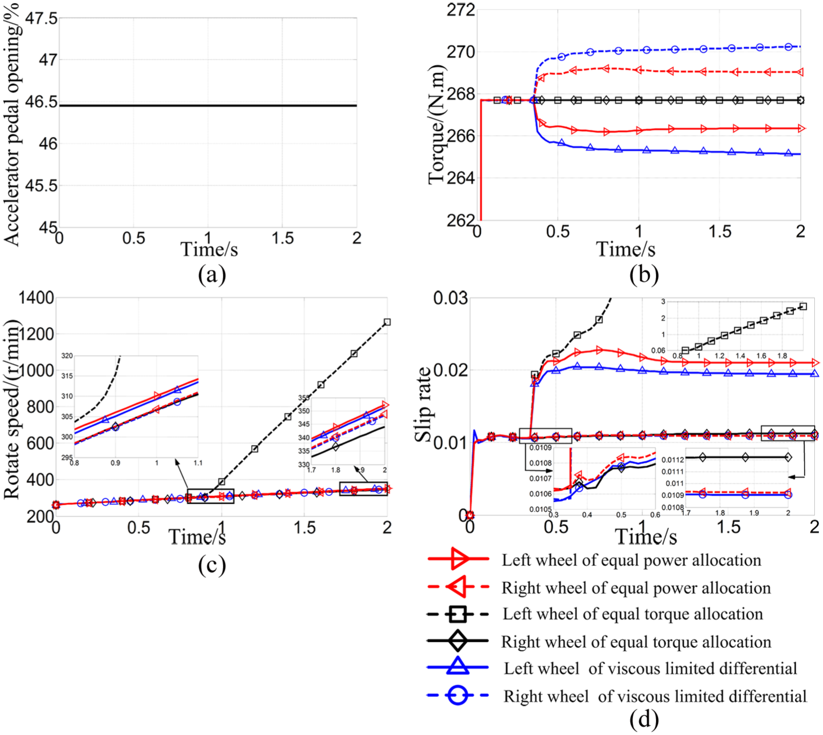
Simulation comparison of straight accelerate driving conditions on bisectional road: (a) accelerator pedal opening signal, (b) drive wheel torque, (c) drive wheel rotate speed, and (d) drive wheel slip rate.
The maximum value of the simulation results of straight accelerate driving conditions on bisectional road.

According to the simulation results, the proposed equal power allocation electronic differential control strategy under straight accelerate driving conditions on bisectional road, throughout the transition from high adhesion coefficient road to low adhesion coefficient road and driving to the bisectional road, the unequal torque distribution of the left and right wheels is achieved. Among them, the wheel on road with low adhesion coefficient has less torque, and another wheel on road with high adhesion coefficient has more torque, which reduces the spin possibility on the road with low adhesion coefficient. At the same time, the wheel rotation speed and slip rate of the left and right wheels have no obvious mutation, in the safe stable area, and no spin occurred on the wheels. Most important of all, the equal power allocation electronic differential control strategy proposed in this article shows that differential control effect and stability are equivalent to those of the electric vehicle with viscous limited-slip mechanical differential, when it accelerates on the low adhesion coefficient bisectional road, which is much better than the equal torque differential control strategy.
Experimental validation
To verify the control effect of EDS based on a wavelet controller, the vehicle test under the turning condition is carried out at proving ground. The test results are compared with the simulation results to verify the effectiveness of the EDS under the actual steering condition. During the turning test, accelerator pedal opening is shown in Figure 16(a). The accelerator pedal opening is always maintained at 10%. When the vehicle velocity arrives at 15 km/h, the steering angle signal is input as shown in Figure 16(b). The torque and wheel speed of left and right drive wheel are shown in Figure 16(c) and (d). Comparison between simulation and test results is shown in Table 7.

Experimental validation of step steering: (a) accelerator pedal opening signal, (b) steering angle signal, (c) drive wheel torque, and (d) drive wheel rotate speed.
Comparison between simulation and test results.

RMSE: root mean square error; MAE: mean absolute error; MAXAE: maximum absolute error; MAXRE: maximum relative error.
Through experiment, we arrive at the following conclusions: (1) the front-wheel-independent drive electric vehicle with equal power allocation EDS based on a wavelet controller can steer safely, stably, and reliably. (2) With the increase in the steering angle, the wheel speed and torque difference between the left wheel and right wheel will increase under the action of the equal power allocation electronic differential strategy based on a wavelet controller. The outside drive wheel rotation speed is higher and torque is smaller, the inside drive wheel rotation speed is lower and torque is larger. (3) Comparing the test result with the simulation result, for left front drive wheel, the maximum relative error of torque is 3.21%, and the maximum relative error of speed is 4.01%. For right front drive wheel, the maximum relative error of torque is 3.37%, and the maximum relative error of speed is 3.75%. Difference between the test result and simulation result is little. So the control effect of the proposed EDS practical application is consistent with the simulation results.
In conclusion, the equal power allocation EDS based on a wavelet controller for a front-wheel-independent drive electric vehicle proposed in this article can realize the difference speed of drive wheel in the steering process. And it can achieve good control effect.
Conclusion
A new equal power allocation EDS based on a wavelet controller is proposed for the front-wheel-independent drive electric vehicle. The control system is composed of two parts. The upper part is the VCU based on equal power allocation, and the lower part is MCU based on wavelet control. And, to verify the performance of the proposed EDS, Carsim/Simulink co-simulation platform and the front-wheel-independent drive electric vehicle test platform based on A&D5435 hardware-in-the-loop simulation system are established. The simulation and test results show the following:
In order to verify stability, real-time and tacking characteristic of MCU based on wavelet controller, study the torque following characteristics of IPMSM under the accelerator pedal continuous step input condition and the steering wheel with large angle input and steering wheel aligning condition. At the same time, compare the traditional PID and fuzzy PID control strategy. The simulation results show that the vector control strategy of IPMSM based on the wavelet controller exhibits excellent control effect, that is, smallest torque overshoot and fastest torque response. And it provides an effective guarantee for the implementation of the equal power allocation electronic differential control strategy.
In order to verify the control effect based on the equal power allocation electronic differential control strategy and the whole control system, the three kinds of extreme simulation conditions of wheels with large rotation speed difference is designed. At the same time, the equal power allocation electronic differential control strategy is compared with the equal torque allocation electronic differential control strategy and the centralized drive vehicle that uses the viscous limited-slip mechanical differential. Study results show the following: (1) under the steering driving condition of the big steering angle input, the equal power allocation electronic differential control strategy shows that the steering control effect and vehicle handling stability are equivalent to those of the equal torque allocation electronic differential control strategy. But the vehicle handling stability is better than the viscous limited-slip mechanical differential. At the same time, the electric vehicle with equal power allocation electronic differential control strategy has a moderate understeering characteristic, which is also very beneficial to the handling stability and safety of the vehicle turning. (2) Under the straight driving condition on the uneven road, the three kinds of control strategies all achieved differential driving, and the slip ratio of the driving wheels was in a stable area, and there is not excessive spin phenomenon. Furthermore, the differential effect and stability of the equal power allocation electronic differential control strategy is better than the equal torque allocation. (3) Under the straight accelerate driving condition on bisectional road and abrupt change of road surface adhesion coefficient, throughout the transition from high adhesion coefficient road to low adhesion coefficient road and driving to the bisectional road, the unequal torque distribution of the left and right wheels of the electric vehicle with the equal power allocation electronic differential control strategy is achieved, which reduces the spin possibility on the road with low adhesion coefficient. At the same time, the wheel rotation speed and slip rate of the left and right wheels have no obvious mutation, in the safe stable area, and no spin occurred on the wheels. Most important of all, the equal power allocation electronic differential control strategy shows that differential control effect and stability are equivalent to those of the electric vehicle with viscous limited-slip mechanical differential, which is much better than the equal torque differential control strategy. Therefore, under the steering driving condition, the vehicle handling stability with equal power allocation electronic differential control strategy is obviously better than that of the viscous limited-slip mechanical differential. Under the straight accelerate driving condition on bisectional road and the straight driving condition on the uneven road, the control effect and stability of the equal power allocation electronic differential control strategy is obviously better than the equal torque control strategy. Therefore, under the three kinds of extreme conditions of wheels with large rotation speed difference, compared with the equal torque allocation electronic differential control strategy and the viscous limited-slip mechanical differential, equal power allocation electronic differential control strategy shows a comprehensive superiority of adapting to the whole condition.
Based on A&D5435 hardware-in-the-loop simulation system, the front-wheel-independent drive electric vehicle test platform is set up. To verify the control effect of the equal power allocation EDS based on a wavelet controller, the vehicle test under the turning condition is carried out at proving ground. The test results are compared with the simulation results to verify the control effect of the proposed EDS under the actual steering condition. Maximum relative error of torque and speed between the test results and simulation results are 3.37%/4.01%. So, the effect of the proposed EDS practical application is consistent with the simulation results.
In conclusion, the equal power allocation EDS based on a wavelet controller for a front-wheel-independent drive electric vehicle proposed in this article shows excellent differential effects, stability, robustness, and vehicle handling stability.
Footnotes
Handling Editor: Haiping Du
Declaration of conflicting interests
The author(s) declared no potential conflicts of interest with respect to the research, authorship, and/or publication of this article.
Funding
The author(s) disclosed receipt of the following financial support for the research, authorship, and/or publication of this article: The authors were supported by Natural Science Foundation of China (Grant: 51507013), China Postdoctoral Science Foundation (Grant: 2017M613034), Postdoctoral Science Foundation of Shaanxi Province (Grant: 2017BSHEDZZ36), Natural Science Foundation of Shaanxi Province (Grant: 2016JQ5012), Science and Technology Research Project of Shaanxi Province (Grant: 2016GY-043).