
Abstract
The transmission system has an important influence on the dynamic performance, endurance mileage, and energy saving in an all-electric vehicle. This article proposes an innovative two-speed seamless dry-friction automatic transmission system to improve the dynamic performance and endurance mileage of an all-electric vehicle with the existing battery technology. The proposed system consists of two-stage epicyclical gear sets without outer ring gears, a dry-friction clutch, and a brake band, realizes a seamless shifting between any two speeds in an electric vehicle. Based on the working principle and dynamic modeling of the proposed seamless dry-friction automatic transmission system, the ratio optimization was carried out to improve the dynamic performance and the power consumption at the same time, and the combination of the weight ratio method and the multi-island genetic algorithm method was introduced to solve the optimization problem. It is shown both theoretically and experimentally that the proposed seamless dry-friction automatic transmission method demonstrates a better dynamic performance and shifting comfort when compared to the automated manual transmission with same transmission ratio.
Introduction
In the recent years, electric vehicle (EV) technology had been developed rapidly due to the air pollution problems and petroleum shortage. The EVs are usually equipped with a single-speed gearbox to minimize the cost, volumes, losses, and drive train mass. 1 However, EVs with a single-speed gearbox require high-performance traction motor and battery to meet the dynamic performance requirements such as maximum climbing slope, velocity, and acceleration. Compared to the single-speed gearbox transmission system, a two-speed gearbox transmission system with the characteristics of vehicle drivability and high efficiency seems to be a more suitable option for EVs.2,3 For this reason, several types and structures of the two-speed gearbox transmission system are proposed for the drive train system of EVs. Among these two-speed transmissions, the simulation and experiments on the two-speed automated manual transmission (AMT) are studied,4,5 and an inverse AMT with the dry clutch located at the rear of the transmissions is introduced to obtain a seamless gear shifting and to avoid the traction interruption of traditional AMT.6–8 Also, a two-speed continuously variable transmission (CVT) and a two-speed dual-clutch transmission (DCT) were compared with the manual transmission (MT) using simulations on several standard drive cycles and found that both the two-speed DCT and simplified CVT improve the overall power train efficiency. However, each of the configurations has unique cost and energy consumption-related trade-offs.9–11
Since the key requirements in an EV are least energy consumption and maximum possible endurance mileage, the AMT is of keen interest because of its lower weight and higher efficiency compared to other types of transmissions, such as automatic transmission (AT), CVT, and DCT. 12 However, a fundamental limitation of the AMT is the power interruption during gearshift due to the restriction of mechanism and principle. Hence, a two-speed transmission system with smooth gearshift and high efficiency is necessary and crucial for the EV transmission. 13
To meet the desired dynamic performance and efficiency for the EV, this article presents a novel seamless dry-friction automatic transmission (SDAT), taking advantages of its mechanical construction and realizing seamless gearshift. The structure and work principle of the proposed SDAT system are introduced. Then, to fit a particular operating driving cycle of the vehicle, the gear ratios are optimized based on the vehicle simulation model using a method combining the weight ratio method and an intelligent optimization method. Finally, the experiments on an EV with SDAT are conducted, and the results show that the EV with SDAT has a seamless upshift.
The structure, working principle, dynamic modeling, and gear ratio optimization for the SDAT system
As mentioned above, the SDAT system has a significant influence on the characteristics of the EV. Hence, a novel SDAT system is proposed considering the basic requirements of EV. The structure, working principle, dynamic modeling, and gear ratio optimization for the SDAT system are presented in this section.
The structure of the proposed SDAT system
As shown in Figure 1, the power train system for EV mainly consists of a battery, motor, SDAT, and final drive. The SDAT comprises a two-stage epicyclical gear set without outer ring gears, as shown in Figures 1 and 2. In Figures 1 and 2, the SDAT system includes dry-friction clutch C, brake band B, input shaft, a front sun gear S1, a rear sun gear S2, carrier, and output shaft. The dry-friction clutch and the brake band are introduced to direct the power flow during the gearshift. The gearbox is divided into two parts. The wet part is used for decorating a planetary gear train, and the dry part is used for decorating the shift control components, such as clutch and brake band. Such design can avoid the quality of gear oil be affected by the wear debris from shift component, improving the operating life time of the gear. The dry-friction clutch is transplanted directly from the clutch of the conventional MT system, and the shift process becomes easier than the MT system since the synchronizer is absent. Therefore, the proposed SDAT has the characteristics of reliable operation and long service. By controlling the speed of the two sun gears, a fast and smooth gearshift is realized. To obtain a smooth gearshift in the brake-to-clutch gearshift of transmission, it is necessary to synchronize the incoming clutch as well as a precise pressure control for the engagement of the off-going brake band. The novel transmission connected to the electric motor and final drive can avoid the need for a torque converter, due to its relatively low efficiency.
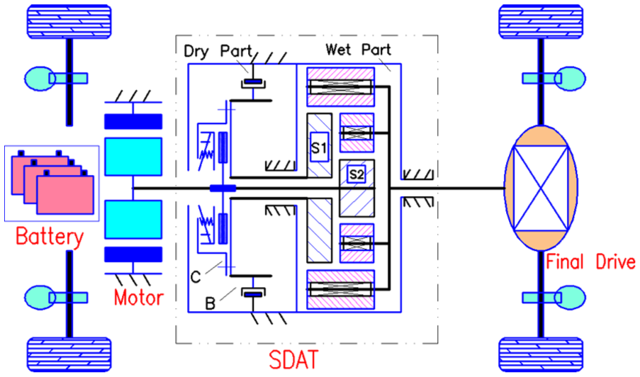
Schematic diagram of the power train system.

A 3D exploded view diagram of gear set.
The working principle of the SDAT system
As shown in Figure 3, the gearshift for SDAT is easy to realize by controlling the working state of the clutch and the brake band. When the clutch C is disengaged and the brake band B is engaged, the SDAT works in the first gear; when the clutch C is engaged and the brake band B is disengaged, the SDAT works in the second gear; when the clutch C and the brake band B are both disengaged, the SDAT works in the neutral gear.
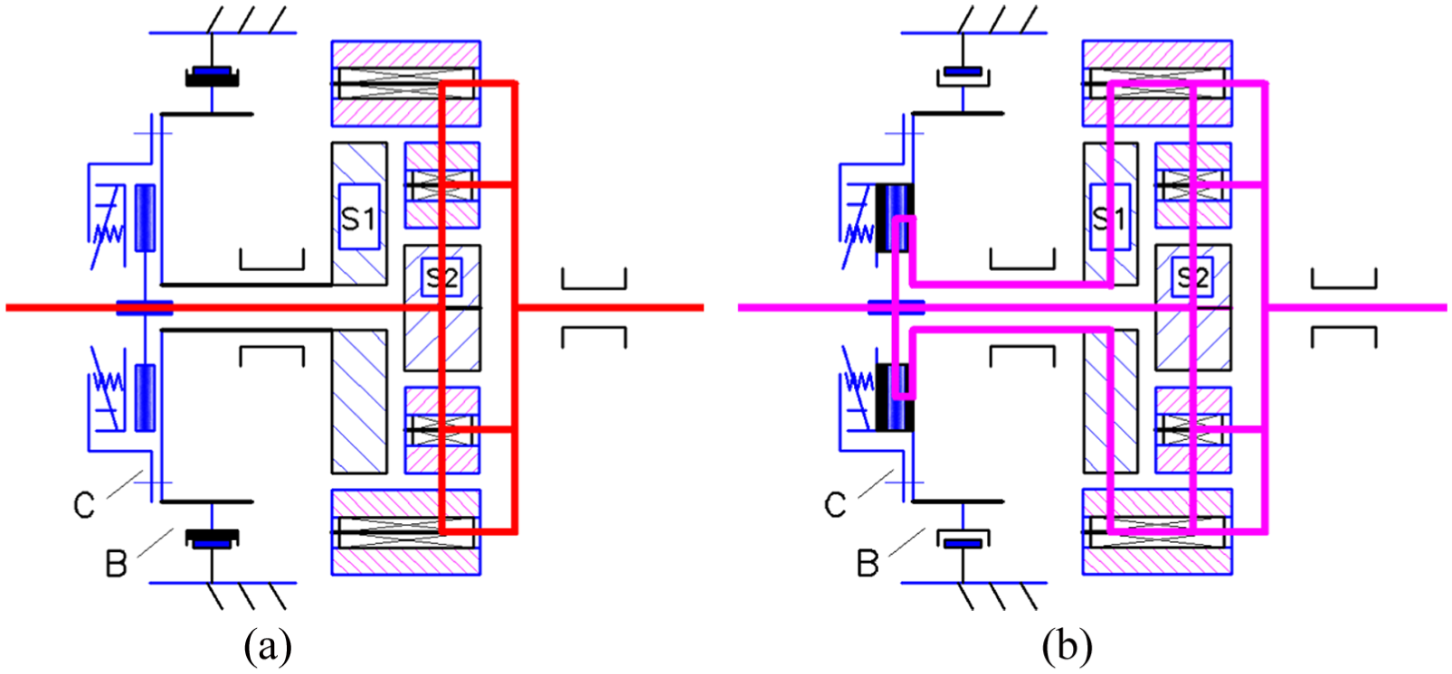
Power transmission path: (a) power transmission in the first gear and (b) power transmission in the second gear.
To understand the working principle of SDAT, the kinematic relation among the front sun gear, the rear sun gear, and the carrier need to be examined in detail. The ratio between the front sun gear S1 and the rear sun gear S2 is proposed by the perspective of standing on the carrier (planetary gear train is simplified to fixed axis gear train) and is given as

where
According to equation (1), the gear set of SDAT has 2 degrees of freedom, and two steps of gear ratios are possible by controlling the working state of clutch and brake band. Since the rear sun gear S2 is connected to the input shaft and the carrier to the output shaft, the gear ratio of the transmission (the ratio between the input speed and the output speed) can be expressed as

where
By examining equations (1) and (2), three different gear ratios can be achievable:
If the front sun gear is completely grounded by engaging the brake band

If the front sun gear and the rear sun gear are fixed together by engaging the clutch

If neither the clutch nor the brake band is engaged

where
Dynamic modeling of the power train system with SDAT
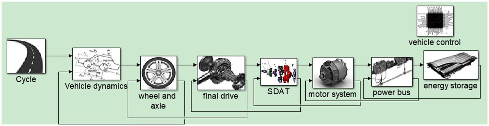
To carry out the ratio optimization task, it is necessary to build a simulation model which includes a driving cycle, energy storage, a vehicle control, and the power train system (as shown in Figure 4). The power train system consists of an electric motor, input shaft, SDAT, output shaft, final drive, and longitudinal vehicle dynamics, as shown in Figure 5. Due to the page constraints, this section only focuses on the model of the power train system with SDAT.
Simulation model for the EV with SDAT.

Block diagram of the power train system simulation model.
Dynamic modeling for motor and flexible input shaft
In this article, the input and output shafts of SDAT are modeled as spring–damp systems, and other components of the power train system are considered as rigid bodies. Thus, the electric motor is considered as a rotating rigid body, and its torque

Then, the equation for the elasticity of input shaft connecting the motor and SDAT can be written as

where angle
Dynamic modeling for SDAT
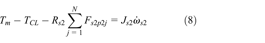
Equation (1) shows the kinetics of the two-stage epicyclical gear system under steady-state conditions. As shown in Figure 6, the dynamic equations of elements for the transmission system built according to the principle of virtual work are as follows

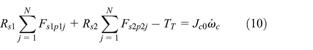
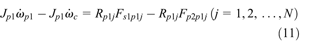
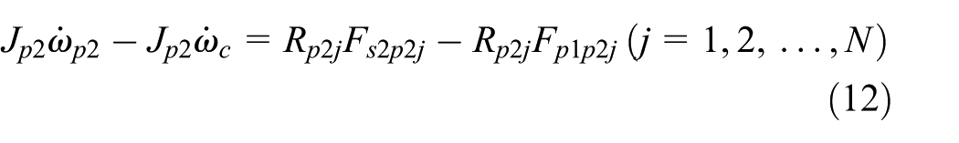

where

Block diagram of the transmission system.
Moreover, the kinematic relationship between the components of the two-stage planetary gear set is


According to equations (1) and (8)–(15), the overall dynamic equations of SDAT system can be obtained as
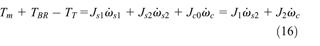

where


For the SDAT system proposed in this article, the clutch connecting the front sun gear and the rear sun gear is same as the conventional single-plate dry clutch type. Thus, the relation between the normal applied force on the plate

where
In this article, the brake of the front sun gear is designed to be of dry band brake type. As a result, the relationship between the applied normal force at the end of the band
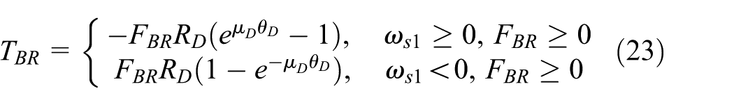
where
In equation (22), the positive rotational direction of brake band is considered as the energizing mode of the band brake.
According to equations (16) and (17), the gear shifting process can be divided into torque phase and inertia phase for analysis. 15 During the shift process, a coordinated control of the clutch, brake band, and the motor is the key to realize seamless shift and change the SDAT output torque smoothly.
Dynamic modeling for final drive and longitudinal vehicle dynamics
Since the output shaft is modeled as a spring–damp system, the output torque of SDAT is expressed as

where angle

Then, using the torque balance equation and lumped mass method, 16 the longitudinal vehicle dynamics can be expressed as follows
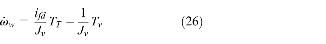
where

where
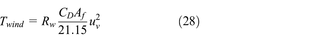


where

By combining equations (6), (7), (17), (25), and (26) together, the full-state dynamics of the system are given as follows
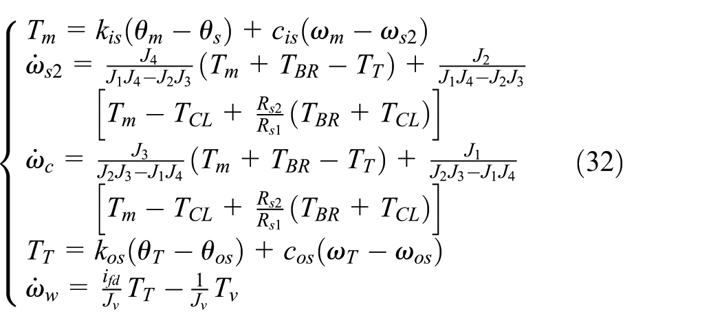
The full-state dynamics of the system was applied in the EV simulation in the next section.
The gear ratio optimization for the SDAT system
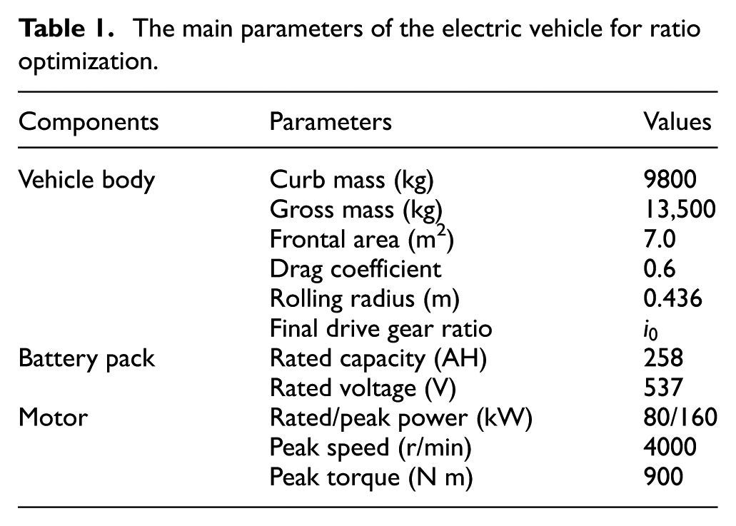
To improve both the dynamic performance and power consumption for EV, finding the desired values of
The main parameters of the electric vehicle for ratio optimization.
The dynamic performance requirements.

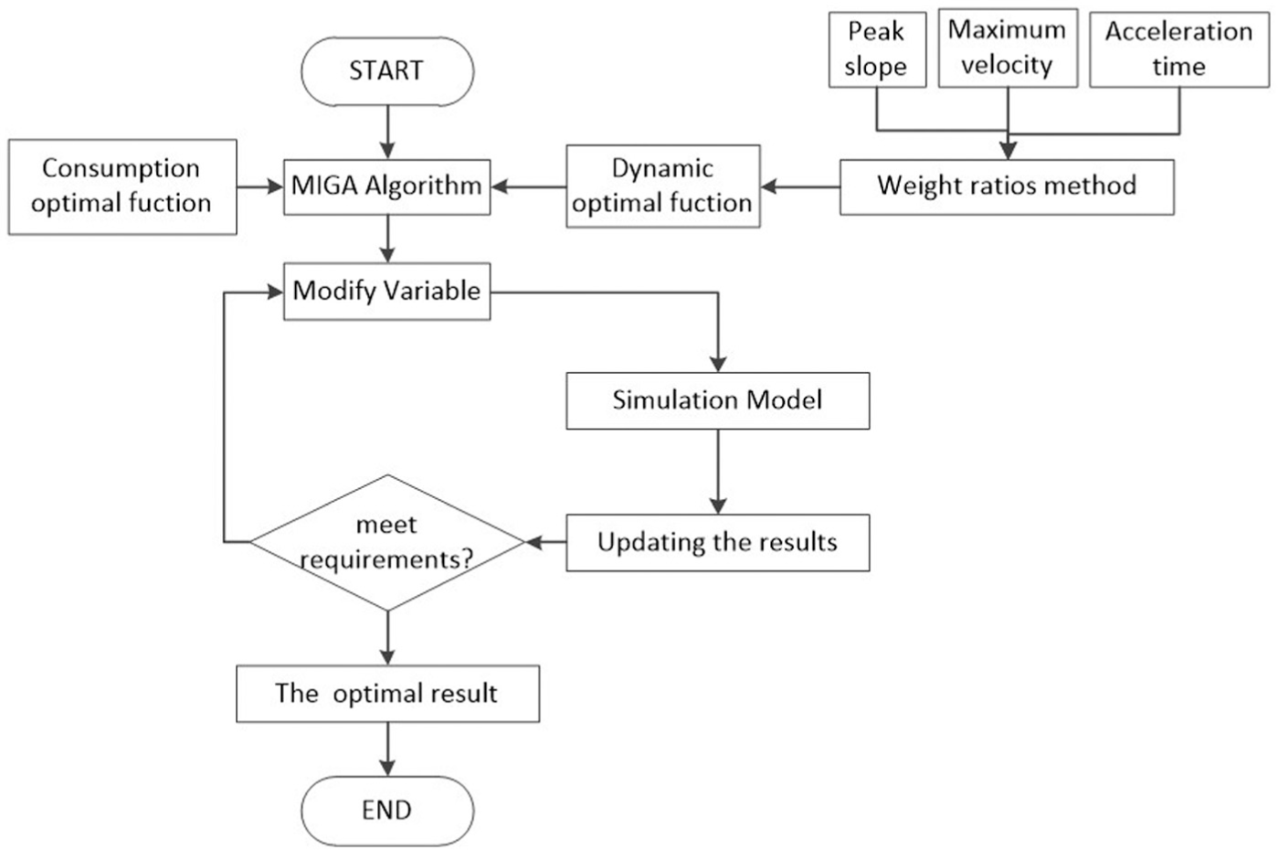
The flowchart of MIGA optimal calculation.
In the optimization process, the weight ratio method was adopted to obtain the dynamic performance objective function from the 0–50 km/h acceleration time, the maximum velocity, and the peak slope. Here, the weight ratio for the acceleration time is 0.7, the weight ratio for the peak slope is 0.2, and the weight ratio for the maximum velocity is 0.1. In addition, the economic objective function was obtained based on the power consumption per kilometer under certain driving cycle. Then, the iterative calculations were carried out using the MIGA method. The optimization objectives and constraints are listed below
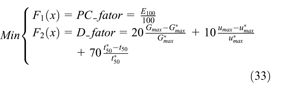

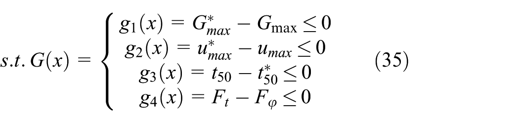
where
MIGA is an advanced version of the genetic algorithm (GA) of parallel distribution, which has not only a better ability to obtain a global solution but also computationally efficient than the conventional GA. According to the rule of “survival of the fittest” in the process of biological evolution, the GA encodes optimization problem solution space of the individual and takes the encoded individual populations into genetic operations (such as selection, crossover, and mutation). Finally, the optimal solution or the combination of the optimal solution can be found through iterations. MIGA divides a large population into a number of subpopulations, called “island,” and uses conventional GA algorithms on each island to carry out subpopulation evolution. The parameters of MIGA are shown in Table 3.
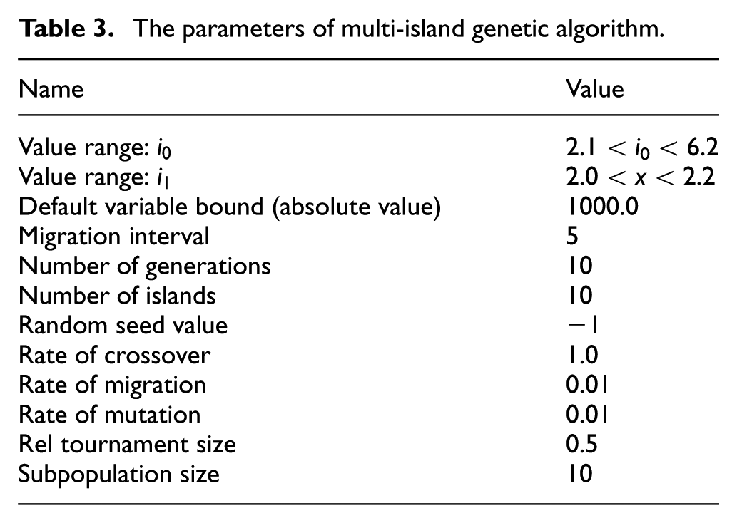
The parameters of multi-island genetic algorithm.
The calculation results for dynamic and power consumption factors are shown in Figure 7. Then, the optimal ratios for
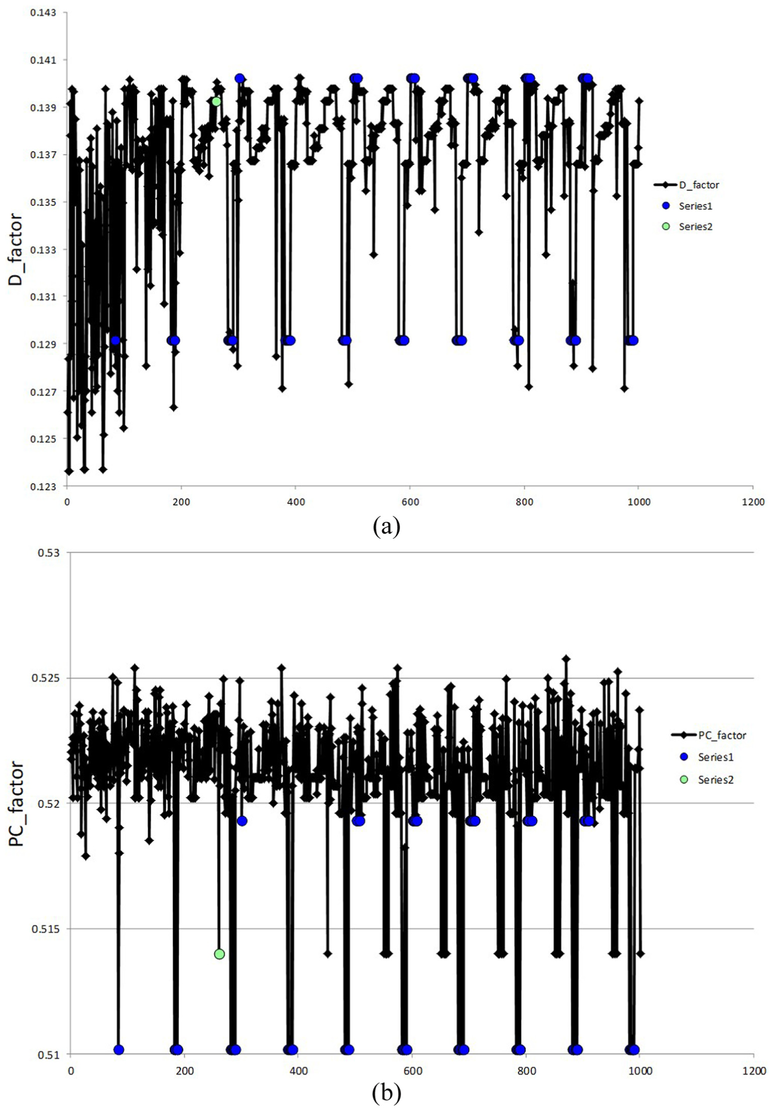
The iterative results of optimization target: (a) calculated history of dynamic factor and (b) history of power consumption factor.
Using the obtained optimal design point, the characteristics of acceleration and peak slope are shown in Figure 9. As shown in Figure 9(a), the peak slope changes with the speed of EV. For example, the peak slope is 21.8% when the EV is operating at 10 km/h. It can also be observed from this figure that the current velocity changes as the acceleration time increases. For example, the 0–50 km/h acceleration time of the EV is about 17.5 s. The maximum velocity of EV in the simulation is about 103 km/h. Under the NEDC.aut driving cycle, the power consumption is about 0.52 kW h/km at the optimal design point. The velocity tracking feature in Figure 10 shows that the current velocity can follow the desired velocity from driving cycle, which means that the dynamic performance satisfies the driving cycle demand.
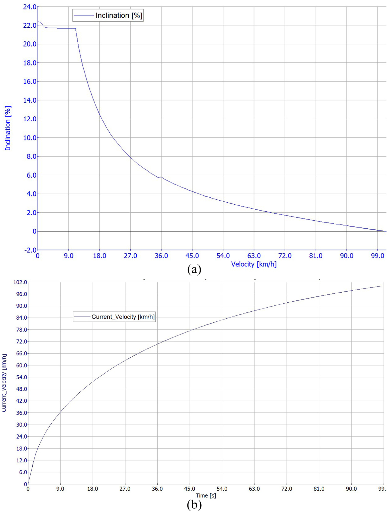
Dynamic characteristic for EV at the optimal design point: (a) characteristics of peak slope and (b) characteristics of acceleration.

Velocity tracking feature in NEDC.aut.
Experimental verification on the vehicle with novel SDAT
After understanding the design and analysis of the proposed SDAT in the previous sections, the seamless shift process was verified by real EV test. As shown in Figure 11, the results from a real driving cycle were obtained from the experiment on the EV with SDAT. Data collection for the motor speed and velocity from the test carried out on EV is presented in Figure 12. The gear shifting characteristics of a upshift process for the EV with AMT is shown in Figure 13, whereas the proposed SDAT method is shown in Figure 14. Based on the test results shown in Figures 12–14, it can be concluded that the vehicle with SDAT has a seamless upshift since the velocity increases steadily during the shifting process, but the vehicle with AMT does not have such smooth shift characteristics. It is worth mentioning that the power consumption per kilometer is about 0.53 kW h/km, and the upshift time is about 0.5 s for SDAT, as shown in Figure 15. As stated earlier, the power consumption obtained in simulations is about 0.52 kW h/km, the simulation accuracy is verified by the experiment result.
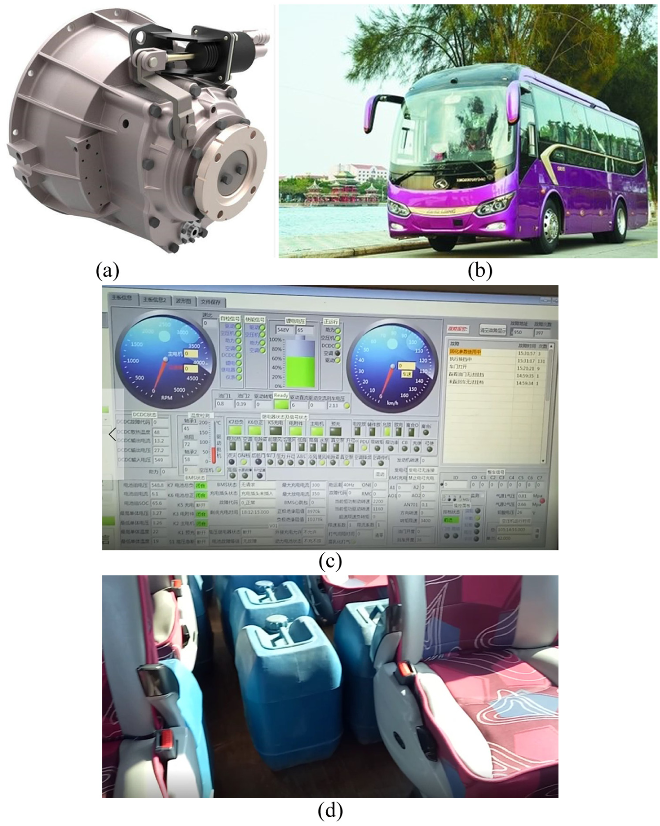
The gearshift and power consumption test: (a) the novel SDAT, (b) the vehicle with SDAT for test, (c) data acquisition software for test and (d) additional weight for test.

Some data from the real velocity test.

Upshift process of the real velocity test with AMT.
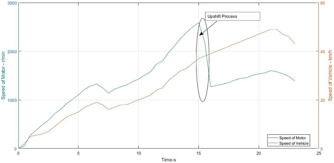
Upshift process of the real velocity test with SDAT.

Gear shifting curve in the test.
Conclusion
This article proposed a novel two-speed seamless transmission with two-stage epicyclical gear sets, a dry-friction clutch, and a brake band. By choosing the optimal design point (
Footnotes
Handling Editor: Haiping Du
Declaration of conflicting interests
The author(s) declared no potential conflicts of interest with respect to the research, authorship, and/or /publication of this article.
Funding
The author(s) disclosed receipt of the following financial support for the research, authorship, and/or publication of this article: The authors would like to thank the financial support from the Fujian Science and Technology Agency (2016H6009 & 2015J01179) and the Nature Science Foundation of China (51275092 & 51505085).