
Abstract
This article focuses on the mode-switch control of a new type of full hybrid electric vehicle with a torque-limiting clutch and an overrunning clutch. The working mode regions of hybrid electric vehicle are divided according to the characteristics of the engine and motor. The target-required torque of the power source in each working mode is determined by a rule-based control strategy for optimal system efficiency. To reduce the torque fluctuation and improve the ride comfort of the vehicle, the coordinated torque control strategy has been proposed during the mode-switch process. The fuzzy control strategy of the oil pressure loaded on the torque-limiting clutch has been put forward. To improve the ride comfort during the mode-switch, the motor has been used for compensation of the rest of the vehicle-required torque according to the clutch-transmitted torque and the output torque of the engine. The dynamic model of the system in each mode-switch has also been established. The simulation has been conducted using MATLAB/Simulink platform for all the mode-switches. Furthermore, the experiment of the motor-assisted engine starting process with the proposed control strategy has been carried out. The result of the experiment is consistent with that of the simulation, and the control strategy proposed in this article is effective for the mode-switch control.
Introduction
The control of the dynamic mode-switch process of hybrid electric vehicles (HEVs) has attracted extensive development interests in the automotive industry in recent years.1–5 If the process is not controlled suitably, the power interruption or much fluctuation of the output torque may occur, which will finally affect the dynamic performance and ride comfort of the vehicle.6–9 Currently, there are many valuable researches on the process of mode-switch about HEV around the world.10–12 However, the clutch control strategy especially at the engaging point during the mode-switch process needs to be further analyzed to make sure the perfect performance of mode-switch. Meanwhile, the researches on mode-switch involving the braking process are also important to be conducted in detail.
In this article, the coordinated torque control among engine torque, motor torque, and clutch-transmitted torque has been proposed for all the mode-switches of HEVs, which effectively makes sure the mode-switch performance in terms of response and smoothness. First, a new type of full HEV with a torque-limiting clutch and an overrunning clutch has been proposed and its working mode has been analyzed systemically. The working mode regions are then divided according to the characteristics of the engine and motor, in terms of efficiency and torque/speed, which is based on a new type of full HEV system structure and working mode analysis. The control strategies for driving mode-switch and braking mode-switch have been proposed, which take the dynamic characteristics of the engine, the motor, and the torque-limiting clutch into consideration. Especially, a fuzzy logic control of clutch oil pressure has been put forward during the mode-switch process. Finally, the effectiveness of the coordinated control strategy for the mode-switches has been validated by both the simulation results and the experimental data.
System structure and working mode analysis
System structure
The structure of full HEV researched in this article is shown in Figure 1. The engine is connected to the motor via an overrunning clutch and a torque-limiting clutch. The torque-limiting clutch can guarantee that the motor has enough power and there is no power interruption in the whole system when the motor starts the engine. The overrunning clutch can ensure that the power can only be transferred from the engine to the motor automatically.
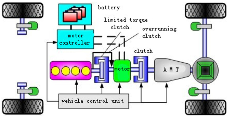
The structure of the full HEV system.
When the torque-limiting clutch is disengaged, the required power is provided only by the motor. The motor can drive the vehicle and start the engine together during the engagement of the torque-limiting clutch. The torque-limiting clutch can limit the motor torque, which ensures that there is no power interruption and the engine starts smoothly. The torque-limiting clutch is then separated and overrunning clutch is locked after the engine starts. Therefore, the vehicle will be driven by the engine alone or by both of them.
Working mode analysis
To analyze the system dynamic of mode-switches, the system dynamic model has been established as shown in Figure 2. Without loss of generality, the role of rotating viscous damping has been ignored.
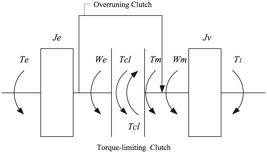
The equivalent diagram of system dynamic mode.
In this research, the vehicle can operate in different modes. 4
1. Pure motor driving mode:
When the vehicle works under low speed or the required torque of the system is small, the vehicle is driven by the motor singly

2. The motor-assisted engine starting while vehicle running:
When the vehicle’s speed is getting higher or the required torque is increased, the torque that the motor provides cannot meet the requirement of the vehicle. At this time, the engine needs to be started. The motor must provide enough power to meet the needs of the vehicle as well as start the engine. After receiving the command of engagement, the torque-limiting clutch begins to work. The vehicle operation mode transfers from the electric driving mode to the engine driving mode. In this process, the equations of motion of this system can then be described as follows

In the equation, Te is the engine dragging torque before the engine started (the engine speed is less than the idle speed). At the beginning of starting the engine, the engine torque is not stable. To avoid the torque fluctuation of powertrain, the motor should not power off immediately but work to compensate the engine torque.
3. Engine driving mode, hybrid driving mode, and charging mode

When it works in engine driving mode, the motor works in a follow-up state and the value of Tm is 0. The engine provides the required torque alone.
When it works in the hybrid driving mode, the vehicle’s required torque is provided by both the engine and motor together. Meanwhile, the overrunning clutch transmits the engine torque.
When the battery needs to be charged, it works in the charging mode. The engine provides the required torque to both motor and vehicle operation. At this time, the value of Tm is negative.
4. Regenerative braking mode

When the brake force is small and the battery state of charge (SOC) is rechargeable, the vehicle works in the regenerative braking mode and the braking torque is provided by the motor. At this time, the motor charges the battery and the Tm is negative. In this situation, the engine works off and the traditional friction braking torque Tf is 0.
When the brake force is high and the battery SOC is rechargeable, but the motor cannot provide enough brake force, the traditional friction braking will work together with the motor. At this time, the engine will still stop.
When the brake force is high or the battery SOC is not rechargeable, the braking force will be provided by the traditional friction braking alone. At this time, the motor will stop and the Tm is 0.
Evaluation criteria
The effects of mode-switch control in HEV can be evaluated by the impact of the vehicle (a measure on sudden change in acceleration) and friction work of the torque-limiting clutch. The friction work can be expressed as below
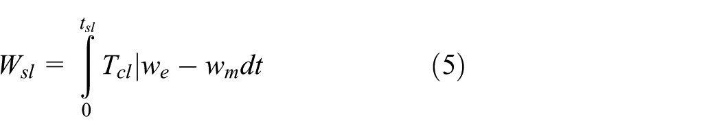
The impact of the vehicle is the derivative of acceleration and can be expressed as below

The process when the motor starts the engine takes a short time (about 0.5 s) and the torque-limiting clutch pressure is small, which shows that the value of Wsl is very small and far less than the limited heat capacity value of the torque-limiting clutch. Therefore, there is no need to take the limited heat capacity of the clutch into account. Therefore, the impact of the vehicle of mode-switch can be measured by equation (6). Different countries have different quantization indexes, and in China the recommended value is
Coordinated torque control strategy
Torque distribution strategy
There are many different kinds of operation modes of the full HEV, so it is needed to divide the operation mode into different regions.14–17 A rule-based control strategy for this full HEV has been proposed for optimal system efficiency. The system operation region has been divided according to the test data of the engine and motor, as shown in Figure 3. In the figure, “a” is the minimum torque curve of engine driving mode (Te_min), “b” is the optimal economic curve of the engine (Te_eff) which is derived from the experiment data, “c” is the minimum torque curve of the hybrid driving mode (engine and motor together; Tm_ass), and “d” is the maximum torque of the charging mode (Te_ch). Therefore, the system operation region had been divided into four parts, which are motor driving mode singly (region 1), engine driving mode (region 2), engine and motor hybrid driving mode (region 3), and charging mode (region 4).

System operation region division.
According to Figure 3, the judgment conditions of each working state are set as shown in Table 1 and the target torques of the motor and engine are shown in Table 2.
Judgment conditions of operation mode.

Target torque of engine and motor.

In the table, Va is the speed of the vehicle and Te_max is the maximum engine torque. When the vehicle-required torque is above curve b but below curve c, the target torque of the engine is Te_eff and the rest of the engine torque provides for charging battery, which can improve the efficiency of the engine and prolong its service life. When the vehicle-required torque is above curve c, the target torque of the engine is Te_max, and the rest of the vehicle-required torque is provided by the motor. In the regenerative braking mode, the target torque of the motor depends on the braking strength and the distribution strategy of braking in the condition that the battery is allowed to be charged.
Torque coordinated control strategy
The response time of the engine torque is longer than that of the motor, which is decided by the throttle open-loop control, the engine transient air–fuel ratio control, and so on. This article illustrates a method to resolving the problem by reducing the torque fluctuation through the coordinated torque control strategy of the engine, motor, and wet torque-limiting clutch.13,16,18–22
Oil pressure control of the torque-limiting clutch
When the mode-switch condition is reached, the engine needs to be started. The torque-limiting clutch will receive the instruction of engagement which needs to control its oil pressure. The basic principle of the oil pressure control of the torque-limiting clutch is as follows: the engagement process should be shortened as much as possible if the ride comfort of the vehicle is satisfied. To reduce the impact of the vehicle during the start of the engine, the motor and the torque-limiting clutch during the engaging process must be controlled coordinately. Because the sliding friction torque is a function of the engaging oil pressure, the engaging pressure of the clutch is controlled through fuzzy logic control.19,23–26
Fuzzy control of initial oil pressure. The opening of accelerator pedal
Fuzzy control of oil pressure during sliding process. After the initial oil pressure of the torque-limiting clutch reaches the target value, the changing rate of engaging oil pressure
Fuzzy logic control rule of increment of initial oil pressure.
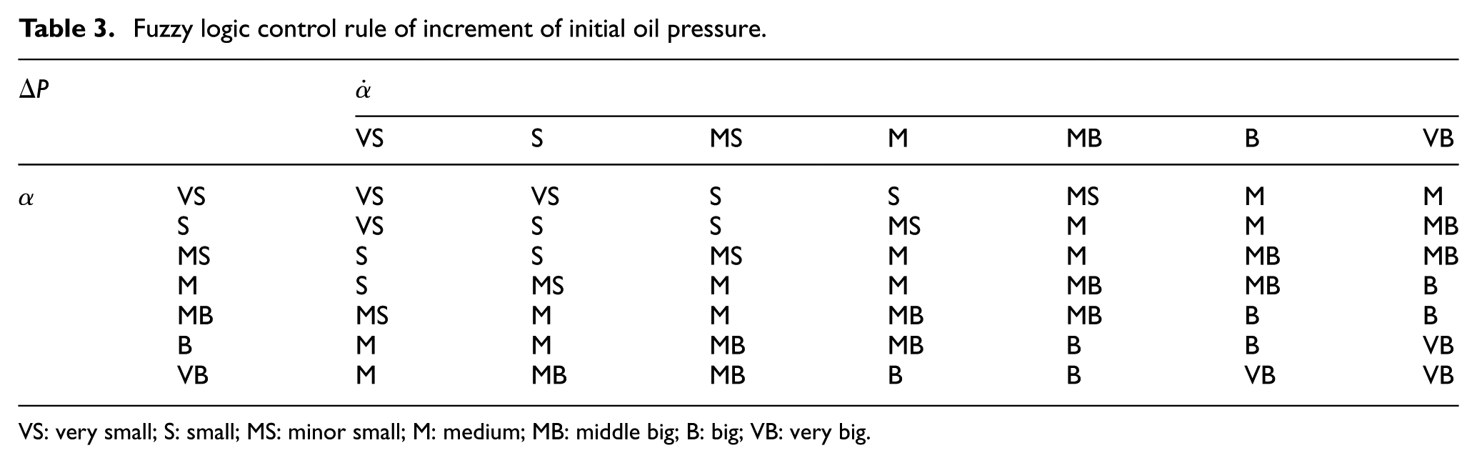
VS: very small; S: small; MS: minor small; M: medium; MB: middle big; B: big; VB: very big.
Fuzzy control rule of changing rate of engaging oil pressure.

VS: very small; S: small; MS: minor small; M: medium; MB: middle big; B: big; VB: very big.
In the sliding friction phase, if the driver pushes the accelerator pedal quickly and heavily, which means the mode-switch process should be finished as fast as possible, the oil pressure changing rate should be increased quickly, and vice versa. When the speed difference between the clutch plates is large, the oil pressure changing rate should be decreased to ensure the vehicle comfort during clutch engaging process. On the other hand, the oil pressure changing rate should be increased to reduce the slipping work as possible.
The integrated fuzzy control system of oil pressure control of the torque-limiting clutch is shown in Figure 4. In this system, dual fuzzy logic control systems have been used for oil pressure control according to the different phases of clutch engaging process, respectively.

The integrated fuzzy control system of oil pressure control of the torque-limiting clutch.
In this process, the clutch torque can be calculated by

where R is the effective radius of the clutch plate (m),
Driving mode-switch control strategy
To realize driving mode-switch process smoothly, the basic principle is coordinated torque control among engine torque, motor torque, and clutch-transmitted torque. The mode-switch process control flow chart is shown in Figure 5. First, according to the signals of accelerator pedal, braking pedal, SOC of battery, vehicle speed, gear ratio and so on, the required torque of the vehicle can be calculated and the target working mode will be confirmed. The instruction of mode-switch is then decided by making a comparison between the current working mode and the target working mode. The switch-flag will be set as 1 if the mode-switch happens. Second, the target torque of power source including engine and motor will be distributed based on the energy management strategy. The coordinated torque control strategy during the mode-switch process is adopted to control the engine, the motor, and the torque-limiting clutch, which make sure they are working coordinately together. Finally, after coordinated control process is finished, the switch-flag will be reset as 0 and the system operation state will be updated and the mode-switch process is finished.

Flow chart of driving mode-switch control.
The driving mode-switch process can be divided into two types depending on whether the torque-limiting clutch is involved or not. The engagement process of the torque-limiting clutch mainly takes place while motor-assisted engine starting. At this time, the motor torque Tm is decided by the vehicle-required torque Td_req and clutch-transmitted torque Tcl, which is also limited by the maximum of the motor torque

In this process, the crankshaft of the engine begins to rotate and the engine is ignited when the speed reaches its ignition point. At this time, the engine controller receives instructions about controlling torque and speed. This process will be completed when the motor and engine are in the same speed. To avoid the torque fluctuation which is caused by the difference between the motor torque and the output torque of the engine, it can be realized through reducing motor torque before the complete clutch engagement. Therefore, the torque fluctuation that results from the engine torque delay can be solved via the motor torque continuous compensation.
The difference between the target torque and the actual output torque of the engine is

The actual output torque of the motor is

That is

where Te is the actual output torque of the engine, Te_req is the target torque of the engine, Tm_req is the target torque of the motor, and δ is the torque difference in the engine. When
In this article, the dynamic output response of the engine mode and motor mode is simplified as the first- or second-order transfer function.5,27 The dynamic output response of the engine mode is

In this equation,
The dynamic output response of the motor mode is5,27

In this equation,
The mode-switch without torque-limiting clutch engagement includes mode-switches of the engine driving mode, motor driving mode, engine and motor hybrid driving mode, and charging mode. The torque changing rate of both the motor and engine should be controlled so as to reduce the torque fluctuation of the switching process.
When the required torque of the engine and motor are changed, the response process must meet the vehicle-required torque. In the mode-switch process, Te_req1 is the engine torque before change and Te_req2 is the engine torque after change rate control. Tm_req1 is the motor torque before change and Tm_req2 is the engine torque after torque change rate control.

And then the required torque is


So the changing rate of the motor torque can be derived

where ke is the changing rate of the engine torque, km is the changing rate of the motor torque, and kreq is the changing rate of the vehicle-required torque. The effectiveness of these changing rate values can be validated by both the simulation and the experiment.
The control strategy of braking mode-switch
In this article, the braking strength can be identified by the opening of the brake pedal and the time derivative of it, which is the same as the driver intention recognition. When the required braking strength is small, according to the braking distribution strategy, the vehicle works in the regenerative braking mode. With the braking strength increasing, it has to switch to the hybrid braking mode including traditional hydraulic brake and motor brake. It is known that there is a delay in response of the hydraulic brake system due to the brake clearance. In this switching process, the motor brake torque makes compensation for the required braking torque to minimize the torque fluctuation and ensure the timely response and good effects of the braking process. The relationship between the hydraulic brake and the motor brake is as follows

In this equation, Tb_req is the required braking torque, Tm_req is the required torque of the motor, Ty_req is the required torque of the hydraulic brake, Tm is the actual motor torque, Ty is the actual torque of the hydraulic brake, and δ is the difference between the required torque and the actual torque.
According to the motor torque compensation, the following expression can be derived

The dynamic response of the braking mode can be simplified as the first-order transfer function

where Pf and Pr are the cylinder pressures of the front wheels and rear wheels, respectively. Df and Dr are the cylinder diameters of the front wheels and rear wheels, respectively. Rf and Rr are the effective radii of the front brakes and rear brakes, respectively. BFf and BFr are the braking performance factors of the front wheels and rear wheels, respectively.
In the actual braking process, the target brake torque of the front wheels and rear wheels can be gained through the distribution of the required braking torque. Then the target torque of the hydraulic brake can be gained through equation (20). Finally, the actual brake torque can be controlled by the hydraulic brake.
The brake torque can be controlled through the above method to make sure that the total braking torque meets the required braking torque. According to the distribution strategy of the braking force, when the braking strength is higher than 0.4, the braking force of the motor begins to decrease. When the braking strength is higher than 0.7, the braking force of the motor will withdraw for braking safety. In this process, as the hydraulic braking is more safe and strong, the brake torque is totally supplied by the hydraulic braking system and the hybrid braking mode will switch to the traditional friction brake smoothly. Finally, the motor can be out of work smoothly. In this process, the coordinated control of the motor braking torque and hydraulic braking torque is highly important to realize braking mode-switch smoothly.
Mode-switch control strategy between driving mode and braking mode
There are two kinds of mode-switches, one is from the driving mode to the braking mode and the other is from the braking mode to the driving mode. If the process of starting engine appears in the first mode-switch, the control strategy has been proposed according to equations (14)–(17). When the vehicle needs to slow down, the braking force will first be provided by the motor. When the required braking force increases, it will enter into the braking mode-switch control. In the second mode-switch, if the vehicle operates in the braking mode-switch control, when the accelerator pedal begins to work, the motor can be used to provide the driving force at first and the motor’s working state will be changed from the braking mode to the driving mode. It will not produce significant torque fluctuation in this process because of no fluctuation of the engine torque.
Simulation analysis
The dynamic and control model of the HEV model has been built in MATLAB/Simulink platform, and all the mode-switches of HEV have been simulated and analyzed. All the data of the vehicle are shown in Table 5.
The list of the vehicle and key components.

ISG: integrated starter generator.
Simulation analysis of motor-assisted engine starting process
In this article, the effectiveness of the mode-switch control strategy is confirmed by comparing the effect with or without control strategy. Without coordinated torque control strategy, the torque of the motor is given directly according to the vehicle-required torque both in the driving mode and the braking mode, which can be seen in the literatures.28,29
The simulation result of the motor-assisted engine starting process is shown in Figure 6. In Figure 6(a), it is the result without control strategy. With the increase in the vehicle-required torque, the engine starts and works individually. This switching process takes less than 0.5 s. However, the motor torque is not yet decreased when engine starts to output torque, so it causes the vehicle torque to increase suddenly. The torque-limiting clutch control during motor-assisted engine starting can be seen in Figure 7. The oil pressure of the clutch increases gradually depending on the pre-set fuzzy logic control rule. The changing rate of the oil pressure satisfies the requirement of mode-switch time and the ride comfort of the vehicle very well. When the clutch begins to engage, the motor withdraws immediately, which results in a decrease in the output torque. The maximum torque fluctuation reaches 38 N m and the maximum impact of the vehicle (jerk) reaches 30 m/s3. In Figure 6(b), it is the result with the torque-coordinated control strategy. The time to start the engine is less than 0.5 s. The motor torque is controlled according to the clutch-transmitted torque and the required torque when starting the engine. When the engagement of the clutch is completed, the motor does not stop working immediately but continues to provide compensating torque. As a result, the maximum torque fluctuation is only 12 N m and the maximum impact of the vehicle is 8.5 m/s3, which is less than the recommended value presented above and satisfies the ride comfort of the mode-switch very well.

The simulation result of engine starting process.

Torque-limiting clutch control during motor-assisted engine starting.
Simulation analysis of the process from pure motor driving mode to driving charging mode
The mode-switch process from pure motor driving mode to the driving charging mode is shown in Figure 8. Figure 8(a) on the left shows the result without the control strategy and Figure 8(b) shows the result with the torque-coordinated control strategy. When the battery’s SOC is low and needs to be charged, the engine starts and the engine provides both the required torque and the motor torque. In this process, the maximum torque fluctuation without the control strategy is 33 N m and the maximum impact of the vehicle is 29 m/s3. However, the maximum torque fluctuation is 11 N m and the maximum impact of the vehicle is only 8 m/s3 with the coordinated control strategy.

The simulation of mode-switch from pure motor driving mode to driving charging mode.
Simulation analysis of the process from pure engine driving mode to hybrid driving mode
The simulation of mode-switch from pure engine driving mode to hybrid driving mode is shown in Figure 9. Figure 9(a) on the left is the result without the control strategy and Figure 9(b) on the right is the result with the coordinated torque control strategy. In this process, as the required torque is bigger than engine maximum torque Te_max, the vehicle-required torque is provided by both the engine and the motor. In Figure 9, it can be seen that the maximum torque fluctuation is less than 3 N m and the maximum impact of the vehicle is only 1.1 m/s3 with the control strategy. However, the maximum torque fluctuation without the control strategy is 18 N m and the maximum impact of the vehicle is 15 m/s3.

The simulation of mode-switch from pure engine driving mode to hybrid driving mode.
Simulation analysis of the process of braking mode-switch
The simulation of braking mode-switch from the regenerative braking mode to hybrid braking mode is shown in Figure 10. Figure 10(a) on the left is the result without the control strategy and Figure 10(b) on the right is the result with the torque-coordinated control strategy. When the system enters into the hybrid braking mode, due to the clearance of friction brake and the delay of establishing stable oil, there will be large braking torque fluctuation. In Figure 10, the maximum torque fluctuation without control strategy is 17 N m and the maximum impact of the vehicle is 11.5 m/s3. In comparison, the maximum torque fluctuation is 8 N m and the maximum impact of the vehicle is less than 6 m/s3 with the proposed control strategy.
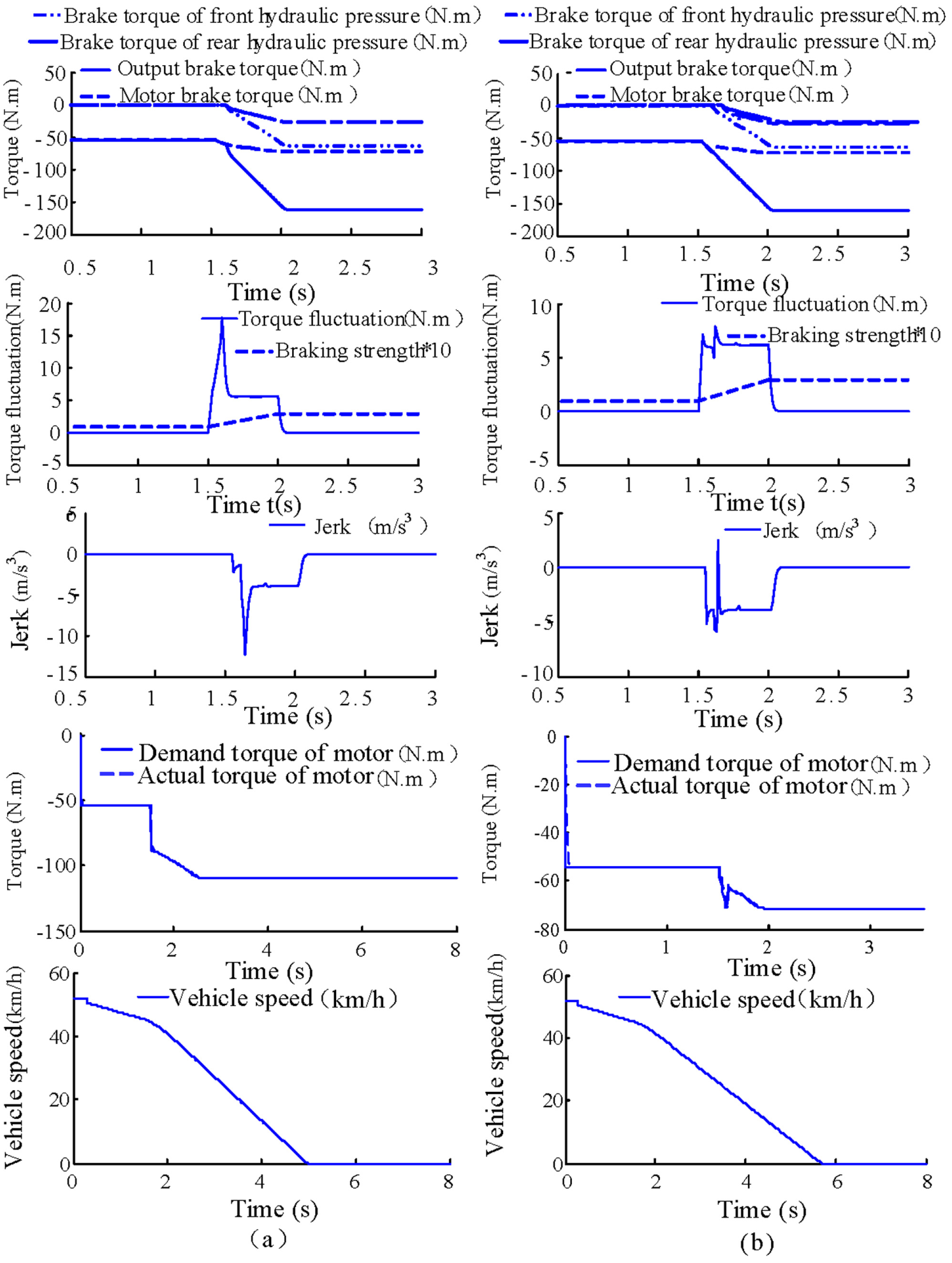
The simulation of mode-switch from the regenerative braking mode to combined braking mode.
Simulation analysis of the process from pure engine driving mode to regenerative braking mode
This simulation of mode-switch from pure engine driving mode to regenerative braking mode is shown in Figure 11. Figure 11(a) on the left is the result without the control strategy and Figure 11(b) on the right is with the torque-coordinated control strategy. With the decrease in the accelerator pedal, the required torque decreases correspondingly and finally reduces to a negative value. The target torque of the engine is 0 and then the engine stops working and the motor provides the required torque. During the braking mode process, when the braking strength is less than 0.1, the vehicle works in pure motor braking mode. With the braking strength increasing gradually, it will enter into the mode-switch process from motor brake to hybrid brake. As shown in Figure 11, the maximum torque fluctuation without the control strategy is 25 N m and the maximum impact of the vehicle is 20 m/s3. In contrast, the maximum torque fluctuation is less than 7 N m and the maximum impact degree is less than 6 m/s3 with the proposed control strategy.
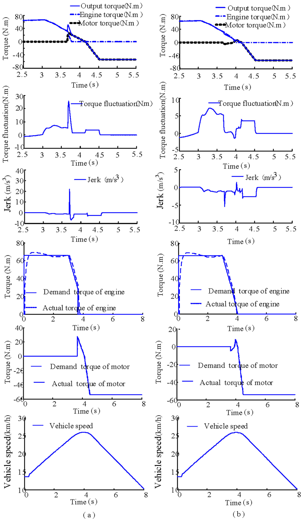
The simulation of mode-switch from pure engine driving mode to regenerative braking mode.
The coordinated torque control strategy proposed in this article has been validated based on the above simulation result. It can be concluded that the torque fluctuation and the impact of the vehicle perfectly satisfied the ride comfort of the vehicle during the mode-switch process.
Experiment of motor-assisted engine starting process on bench test
The bench test system for the hybrid electric system has been built up, which can be seen in Figure 12. The hybrid test system consists of engine, motor, nickel hydrogen battery, power coupling mechanism, transmission, braking system, loading system, data acquisition, and control system. The power source including an engine and a motor is integrated by the power coupling system. The power source of the motor is provided by the nickel hydrogen battery. The hydraulic pump station provides the hydraulic power for engaging torque-limiting clutch and lubricates the power coupling device. The braking system is composed of the brake pump and hydraulic disk brake. The vehicle inertia is simulated by inertia flywheel. The resistance of the vehicle is simulated by the dynamometer. There are several sensors such as speed/torque sensors located on the test bench. The control software is developed using MATLAB/Simulink platform, and the dSPACE is used as the controller of HEV.

The experiment field of the hybrid electric vehicle.
As is well known, the process of motor-assisted engine starting is the most difficult to make sure the engine starts smoothly and to improve the ride comfort of the vehicle. Therefore, the test of mode-switch of motor-assisted engine starting has been conducted to verify the effect of the control strategy on test bench. The comparison of the experiment result and the simulation result during motor-assisted engine starting process can be seen in Figure 13.

The comparison of the experiment results and simulation results during motor-assisted engine starting process.
As shown in Figure 13, Figure 13(a) on the left is the experiment result with the proposed control strategy, Figure 13(b) in the middle is the experiment result without the control strategy, and Figure 13(c) on the right is the simulation result. First, the vehicle operates in pure electric mode. At 65.8 s, the working mode of the vehicle is transferred from the electric driving mode to the engine driving mode. The torque-limiting clutch C2 begins to engage and the motor torque increases rapidly. When the motor torque is increased to 73 N m, the engine starts to rotate. When the engine speed is close to the speed of the motor, clutch C2 engages quickly and the overrunning clutch is locked completely. In Figure 13(a), after the engine starts, the motor torque is reduced to 0 gradually. Finally, the vehicle operates in the engine driving mode. In this process, the maximum fluctuation of the output torque is about 108 N m, and the maximum impact of the vehicle is about 5.52 m/s3. In Figure 13(b), the motor torque is reduced to 0 directly and the maximum impact of the vehicle is about 19.95 m/s3. The impact of the vehicle during the experiment process is reasonable, which indicates that the control strategy of motor-assisted engine starting is effective in terms of mode-switch smoothness.
In Figure 13(a), the motor torque increases rapidly to compensate the dragging torque of the engine and then gradually reduces to 0 after the engine ignition to compensate the difference between the actual torque of the engine and the target torque. The coordinated control of the engine, motor, and clutch reduces the fluctuation of the output torque of powertrain and ensures the ride comfort during motor-assisted engine starting process, which can be seen through the last two plots in Figure 13(a). Comparing Figure 13(a) with Figure 13(c), the experimental results are highly agreeable with the simulation results, and the effectiveness of the proposed control strategy for motor-assisted engine starting is validated by the comparison between the simulation results and the test data.
Conclusion
This article focuses on the mode-switch control of a new type of full HEV with a torque-limiting clutch and an overrunning clutch. The dynamic model of HEV is established and the working mode regions are divided according to the characteristics of the engine and the motor. A rule-based control strategy for this full HEV has been proposed for optimal system efficiency, which provides a foundation for the proposed coordinated control strategy.
The fuzzy control strategy of torque-limiting clutch and coordinated torque control strategy have been proposed. The fuzzy clutch control consists of initial oil pressure control and engaging oil pressure control, which make sure the engagement of clutch rapidly and smoothly during mode-switch process. Taking the dynamic characteristics of the engine, motor, and the torque-limiting clutch into consideration, the coordinated control strategy for all the mode-switches of HEVs, including both driving mode-switch and braking mode-switch, has been put forward for ensuring the mode-switch performance in terms of response and smoothness.
To verify the proposed control strategy, the simulations of each mode-switch have been conducted in this article. The results show that the control strategy can reduce the fluctuation of the torque and the impact of the vehicle effectively. Furthermore, the experiment of the motor-assisted engine starting process with the proposed control strategy has been carried out. The effectiveness of the coordinated control strategy for the motor-assisted engine starting process has been validated by both the simulation results and the experimental data.
Footnotes
Academic Editor: Jose Ramon Serrano
Declaration of conflicting interests
The author(s) declared no potential conflicts of interest with respect to the research, authorship, and/or publication of this article.
Funding
The author(s) disclosed receipt of the following financial support for the research, authorship, and/or publication of this article: The work presented in this article was supported by the National Natural Science Foundation of China (no. 51575063), the Major Application Development Project in Chongqing (CSTC2015yykfc60003), and the Fundamental Research Funds for the Central Universities (project no. 106112016CDJXY330001).