
Abstract
In order to obtain the satisfied rock-breaking requirements, the layout of cutter-head system of tunnel-boring machine are optimized and analysed to work efficiently by the scientific and reasonable design. An integrated method which can optimize exactly the cutter-head system considering equivalent life principle and force balance based on Archimedes spiral theory is proposed in this article. The effect of installation radius of cutter on wear coefficient and tunnelling coefficient is analysed using equivalent life principle. The force balance models are established using optimization of cutter arrangement. The comparison between the simulation and experimental results shows that the kinematic and dynamic of cutter-head system are reasonable based on Archimedes spiral method. It can be concluded that, therefore, the proposed integration method can offer a theoretical foundation and reference for dynamic optimal design for cutter-head system.
Keywords
Introduction
Tunnel-boring machine (TBM) is a machine to drill complex rocks and excavate tunnels underground. The cutter-head system is one of the most important parts in TBM; deteriorations on cutter discs, thus, have become one of the largest limitations in rock TBM tunnelling process.1,2 The optimization of the cutter-head system layout is to obtain the maximum cutter life at the minimum cost. Therefore, the dynamic optimization design of TBM is directly relating to the disc cutter arrangement and affects the efficiency of TBM excavation before manufacture.3–5
There are several studies on the cutter-head design of TBM. Acaroglu et al. 6 predicted the amount of energy required to excavate a unit volume of rock of constant cross-sectional disc cutters in the rock-cutting process using alternative methods. This model predicted specific energy requirements of disc cutters and was established based on the database created by the Colorado School of Mining. Huo et al. 7 employed the ant colony optimization (ACO) algorithm to solve the disc cutter plane layout problem. 8 Meanwhile, an example of disc cutter layout design was also generated by the ACO algorithm to prove the feasibility and effectiveness of this method. The numerical results showed that the ACO algorithm can provide engineers with methods to decide disc cutter layout. Wei et al. 9 have demonstrated a dynamic model of multi-gear drive in TBM to investigate the impact of inertia on the cutter-head and the drive mechanism. Rostami 10 has proposed some cutter-head models based on the estimation of the cutting force and discussed their advantages and disadvantages. Those models can be employed in the cutter-head design optimization and performance estimation. Haeri et al. 11 have studied the linear elastic fractural mechanics of rock and maximum shear stress criterion and estimated the stress intensity factors of a single-disc cutter based on higher-order indirect boundary element methods. Zhang et al. 12 analysed the forces on disc cutters of full-face rock TBM cutter plate. They built a model according to the actual rock breaking, proposing the principle of layout of hob on cutter plate and verifying this model with experiments. Their theory stated that forces on the cutter plate have to be balanced between the moment of force loaded on the cutter disc, the coordinate axis of the cutter-head rotation centre and the components in the coordinate axis when the full-face rock TBM is working. Lin et al. 13 optimized the layout of TBM gauge disc cutters, analysed its objective function and constraint condition function and solved it using a genetic algorithm. Qi et al. analysed the influence of the layout of TBM face cutters on consumption. The results showed that the two-spiral layout pattern was better than other layout patterns in terms of the cutter consumption and the cutter-head force balance. They also investigated the rock-cutting process of TBM gauge cutters based on the full-scale rotary cutting machine.14,15
The reasonable layout of cutter-head system ensures the maximum cutter life and the minimum cost per volume of rock excavation. There are three basic principles in the layout of cutter-head system: (1) the geometry principle of disc cutters layout (the layout curves on cutter-head system), (2) the quantity of layout disc cutters and (3) the force balance in the cutter-head system. Therefore, an integrated method optimizing the cutter-head system based on the equivalent life principle and on the force balance derived from the Archimedes spiral theory is proposed in this article.
The organization of this article consisted of the following sections. The cutter-head layout is proposed based on the Archimedes spiral theory in section ‘Cutter-head layout based on Archimedes spiral theory’. In section ‘Tool layout optimization on the principle of equivalent life’, the disc cutter layout is analysed and optimized using the principle of equivalent life. In section ‘The disc cutter layout based on balance of tool force’, the force balance models are established using optimization of cutter arrangement. The comparison between the simulation and the results of experiment is analysed in section ‘Kinematic/dynamic analysis and rock-breaking process’. In section ‘Conclusion’, some conclusions from this study are presented.
Cutter-head layout based on Archimedes spiral theory
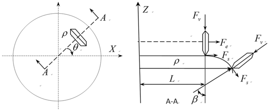
The spiral of Archimedes is called the isovelocity spiral. When a point moves along the polar diameter uniform linear and the polar radius itself does a uniform angular velocity rotation movement, the moving point’s trace is called the Archimedes spiral. Archimedes spiral and parameters of layout are shown in Figure 1. In polar coordinates, the Archimedean spiral can be described by the following equation

where

(a) Archimedes spiral and (b) parameters of layout.
Considering the overlap on the cutting paths, the layout of disc cutters on the plate has two situations: no overlapping arrangement between the cutting paths and the overlapping arrangement between the cutting paths. When considering no overlapping arrangement on the cutting path of disc cutters, the number of tangent disc cutters arranged on the plate is given as follows

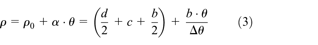
where D is the cutter-head system diameter, d is the central cutter’s maximum diameter and b is the distance between disc cutters.
The Archimedes spiral equation of cutters arranged on the plate is expressed as follows
where
The cutter arrangement of polar coordinate values is shown in Table 1. The polar coordinate value and polar angle can be calculated by the Archimedes spiral equation. Cutter-head system and actual scraping trace based on single Archimedes spiral is shown in Figure 2, which is used to reduce cutter wear and improve the force balance.
Cutter arrangement of polar coordinate values.


Cutter-head system 1 and actual scraping trace: (a) disc cutter-head system and (b) the track of rock breaking with disc cutters.
Tool layout optimization on the principle of equivalent life
Disc cutter wear has two forms: one is the uniform wear, and the other is irregular wear. The uniform wear features approximately equal wear degree throughout the cutting ring, as shown in Figure 3(a). This radial wear is measured. When wear height is more than 20 mm, the disc cutters are invalid. It can be shown that the uniform wear is the main failure form of disc cutters in engineering practices. Therefore, this research has important practical significance. Irregular wear features different wear degrees around the cutting ring, as shown in Figure 3(b). There are two types of non-uniform wear mechanism, string eccentric wear and blade eccentric wear, which account for most of wear in engineering applications.

Wear of disc cutters: (a) uniform wear and (b) irregular wear.
Disc cutter wear prediction model used in a large number of shield construction is expressed as follows

where
The impact factor of disc cutters within the wear life is formulated as follows

To determine the number of tools on different cutting radii, the disc cutter’s radius position can be expressed as follows

When certain amount of wear, construction requirements and boring parameters are determined, the critical wear coefficients to adapt and critical boring coefficients can be obtained. The two methods are separately called wear coefficient method and tunnelling coefficient method. The figures of wear coefficient and boring coefficient are shown in Figure 4, where abscissa represents the fixing radius of tools and ordinate represents wear coefficient or boring coefficient. It can be noticed in Figure 4 that the increasing fixing radius, wear coefficient increases. Therefore, the critical coefficient and the radius are certain, and the number of disc cutter increases.

Wear coefficient as the disc cutter radius variation.
It can be seen in Figures 4 and 5 that when installation radius of disc cutter increases, the tunnelling coefficient decreases, and the number of necessary cutters increases when the tunnelling coefficient remains unchanged. The values of critical wear coefficient are exactly equal to the limit of the maximum wear amount. The values are higher than critical tunnelling coefficient represent. Tunnelling distance is larger than distance in requirements. In Figures 4 and 5, the minimum amount of tools needed can be obtained to meet different cutting radii based on tool wear life principle. The least number of disc cutters in different installation radii is shown in Figure 6.
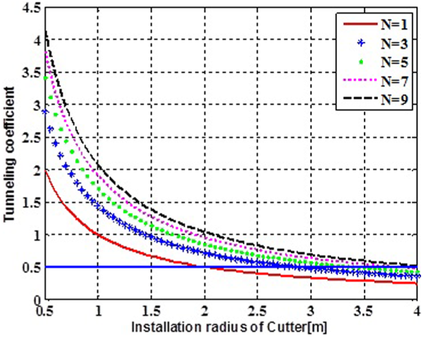
Tunnelling coefficient as the disc cutter radius variation.

The least tools in different installation radii.
The double-spiral expressions of cutter-head system are given in equation (7). The layout curves of double-spiral lines are expressed in Figure 7 based on the spiral equation

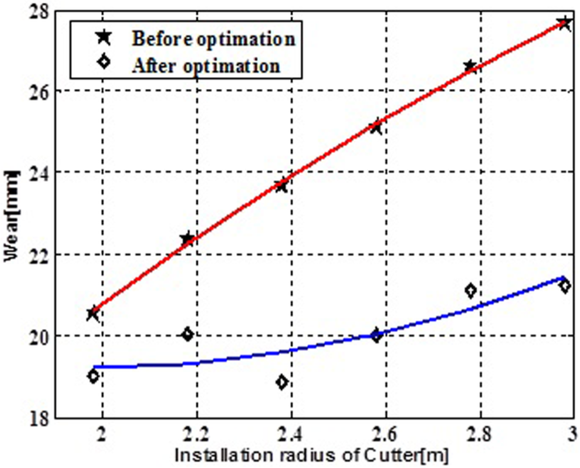
According to life principle of tool wear, if the cutting radius r is less than 1910 mm, the main disc cutters can be arranged by Archimedes single-spiral curve. If the cutting radius r is in the range of 1910–2410 mm, the disc cutters adopt double-spiral curve layout. And when the cutting radius r is more than 2410 mm, three disc cutters are used to meet the principle of tool wear life, but to ensure the symmetrical structure and force equilibrium, four disc cutters are used in each circle spiral curve. Wear before and after optimization is compared in Table 2.
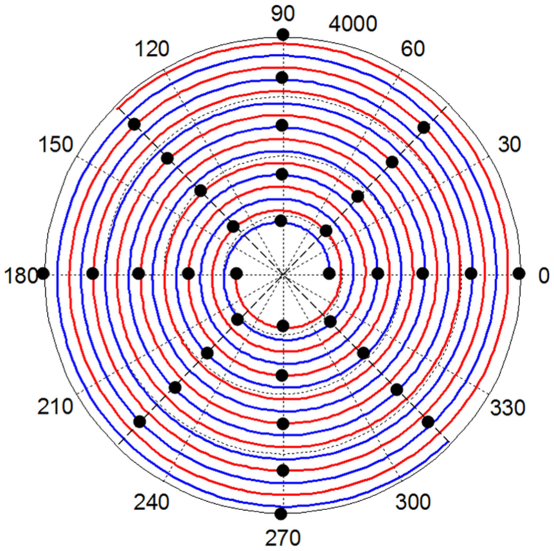
The double-helix and disc cutters layout.
Comparing wear before and after optimization.

It can be noticed in Table 1 and Figure 8 that the wear of disc cutters and variance distinctly decrease after optimization. Therefore, the life of disc cutters and tunnelling efficiency are improved, and the change frequency of disc cutters is declined.
Wear is compared before and after optimization.
The disc cutter layout based on balance of tool force
The analysis of disc cutter force
Disc cutters are key components of TBM on the continuous rotating cutter-head system. Disc cutters’ wear is closely related to the tunnelling forces in different directions. When the disc cutters are tunnelling, the forces on disc cutters will be divided into vertical force, the rolling force, inertial force and the lateral force, as shown in Figure 9.
Force models of disc cutters on cutter-head system.
The vertical force is a counterforce on working surface of rocks when disc cutters are tunnelling under the thrust forces. The relationship between vertical force and the plane of cutter-head is perpendicular to each other.
The equations of vertical force, rolling force and inertial force are expressed as follows

where m is the quality of disc cutters,
The vertical forces on disc cutters come from the thrust forces, but thrust forces derive from the TBM slewing hydraulic propulsion cylinder. And the structure and the number of disc cutters installed determine the maximum thrust forces. If the number of disc cutters installed on tools is fixed, each disc cutter can load increasing force, and consequently, the total thrust on tools can withstand greater forces. When the total rated thrust on boring machine is certain, much more disc cutters can be installed on the cutter disc, and vertical thrusts on each disc will correspondingly decrease, and the depth of breaking rock surface will decrease too. Therefore, the disc cutters installed on it should not be too low to ensure every cutter can obtain adequate thrust to breaking rocks. As the vertical forces on disc cutter, rolling force is the counterforce on cutters along rock surfaces on the disc cutter tunnel. The rolling force paralleling to the working face of the cutter and along the tangent direction along the disc cutter can produce torque on disc cutters but not generating excessive torques. The inertial forces from the relative motions on disc cutter can balance with each other. Inertia force generally in couple forms affects the cutter force balance when the disc cutters tunnel.
Force balance analysis of disc cutter
The layout of disc cutters should meet the requirements of project and balance the forces on disc cutter. To improve the stresses of disc cutter and decrease the vibration and the noise of machines in tunnelling, the overturning moment has to be considerably less so as to reduce radial forces on bearings to zero. The force balance of disc cutter in section i is expressed as follows
where
The radial unbalanced force on cutter-head system
The rolling force, inertia force and the lateral force acting on the disc cutters will generate unbalanced radial forces in the plane of the cutter-head or parallel to the plane cutter. In this situation, positive disc cutters are arranged on cutter-head system, so the radial unbalanced force produced by cutter is small, and it will not be considered. Then, the radial unbalance force of the disc cutter on the x shaft and y shaft should satisfy the following relations

where
Optimization of cutter-head system
The disc cutter layout optimization is usually considered in two ways which are cutter spacing and the installation phase angle. In this geological condition, the disc cutters’ cutter spacing being about 95 mm is appropriate. However, considering the tool wear, the tunnelling speed will get down. Therefore, mainly considering from the optimization of disc cutter installing angle issue, 100 mm is an adequate distance for original disc cutter without improvement. Due to the disc cutters in the spokes arranged at two sides of the slurry balance disc cutters and to maintain cabin pressure of cutters, it is inappropriate to arrange disc cutters on panels. Consequently, the disc cutters should be arranged and optimized.
The positive disc cutter layout is arranged on three Archimedes spiral curves. The layout of adjacent disc cutters is arranged in central symmetry manner without other parameter changing. The first and second Archimedes spiral clockwise arrangements are from 0° phase angle. The Archimedes spiral clockwise arrangement is from 0° phase angle. The third Archimedes spiral clockwise arrangement is from 180° phase angle. The equations can be expressed as follows

The optimized tool parameters are taken into equation (11) to check the radial unbalanced forces and overturning moments on disc cutter. It can be shown in Table 3 the comparison of optimized radial unbalanced forces and overturning moments on disc cutter and non-optimized ones. Accordingly, the overturning moments decrease greatly with partial load effect reducing on disc cutter. Therefore, the optimized layout of disc cutter wins over the original one (Figure 10).
Compared before and after optimization.


Layout of cutter-head system after optimization.
Kinematic/dynamic analysis and rock-breaking process
Kinematic/dynamic simulation of cutter-head system
ADAMS, as employed in this article, is one of the most popular VP platforms. Modelling in ADAMS/View directly is not only convenient and rapid but also helpful for mechanism on simulation and analysis. The cutter-head can be directly embedded in the solution in ADAMS. The establishment of disc cutters system is shown in Figure 11.

The disc cutter system in virtual prototype.
Taking the cutter system for example, first, the kinematics and dynamics simulations are proceeded under the initial conditions (which may be different from the practical situations). First step, the rotating speed of cutter driving system is increased to 100°/s. Then, the system makes a uniform rotation with this speed. Finally, the speed will decline to zero. The simulation of driving force proceeds in function form.
Figure 12 shows the curve of disc cutter linear speed as well as in the space and in the tool system. The angular velocities become gradually stable. But in the uniform moving progress, the speed curves of two directions are both in sinusoidal form. Through centrifugal force rules of calculation and analysis, the centrifugal force on blade increases with increasing radius (Figure 13). When edge scraper makes uniform rotating, the force curve is sinus 1. While in acceleration and deceleration, the centrifugal force rapidly changes, as shown in Figure 14. The forces are conducted in Figure 15. Distribution of shear stress and Misses equivalent stress distribution is obtained by the simulation analysis.

The curve of edge scraper’s linear speed in multi-direction and angular speed: (a) linear velocity and (b) angular velocity.

Displacement curves of disc cutters in different positions.
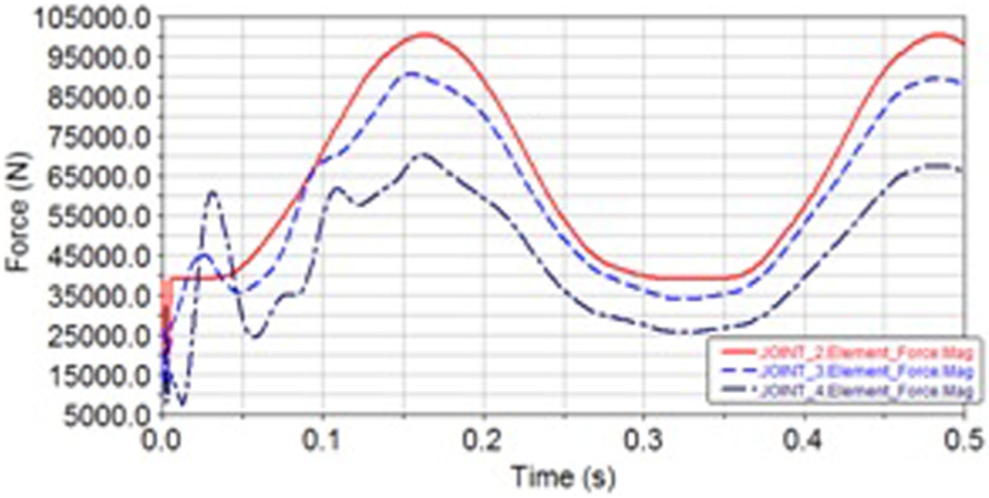
Force curves of disc cutters in different radii.
Simulation analysis of disc cutters: (a) the actual layout and distance of disc cutters, (b) distribution of shear stress and (c) Misses equivalent stress distribution.
The force measures in rock-breaking process
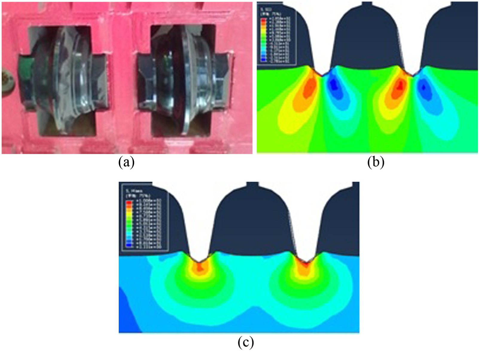
The longitudinal forces of disc cutters are measured on double-disc cutters. In conjunction with this work, theoretical and empirical models have been proposed to predict disc cutter forces. The disc-cutting tests were performed on the rock-breaking machine (Figure 16).
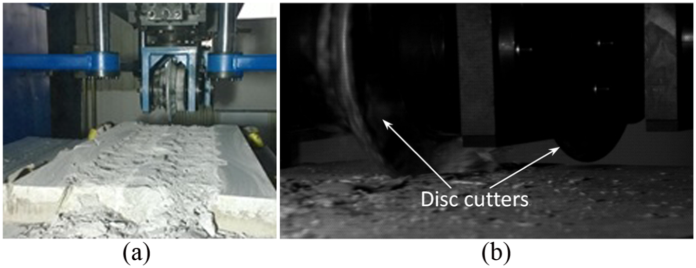
Rock-breaking process in experiment (the penetrations are 5 mm, cutting speed is 1.5 m/s and tools are 17 in).
It can be seen from Figure 17 that rock-breaking stresses increase with the disc cutters’ cutter spacing becoming larger. When the cutter spacing is small, a rock’s large part between two disc cutters is still in the crushed zone range and broken rock powder account for a higher proportion. Usually, damage and fractures are finite between two disc cutters and crack coalescence in certain depth then forming sheet rock. When the cutter spacing is increased, crack failure caused by single-disc cutters is difficult to expand, resulting in the intermediate formation of rock ridge, but there is still a part of the rock not broken, which cannot be separated completely from the original rock. When the cutter spacing is small, the rock is broken much too excessively between two disc cutters resulting in a deeper penetration of disc cutters. With the penetration increasing, the vertical force increases slowly. When the cutter spacing increases continuously, the growth trend of the vertical force becomes more obvious. The vertical force values close to the vertical force when two disc cutters are cutting separately.

Vertical boring forces with different cutting spaces.
Conclusion
The optimal layout of cutter-head system is proposed based on Archimedes spiral theory. The effect of installation radius of disc cutter on wear coefficient and tunnelling coefficient is analysed using equivalent life principle.
The force balance models of cutter-head system are established using optimization of cutter arrangement based on Archimedes spiral theory. The radius unbalance force is compensated after optimization.
The comparison between the simulation and experimental results shows that the kinematic and dynamic of cutter-head system are reasonable based on Archimedes spiral method. Therefore, the proposed integration method can offer a theoretical foundation and reference for dynamic optimal design for cutter-head system.
Footnotes
Handling Editor: Yangmin Li
Declaration of conflicting interests
The author(s) declared no potential conflicts of interest with respect to the research, authorship and/or publication of this article.
Funding
The author(s) disclosed receipt of the following financial support for the research, authorship and/or publication of this article: This project was sponsored by the Youth Program of the National Natural Science Foundation of China (grant nos 51502034 and 51505075), Liaoning Ministry of Education Research Fund (grant no. L20150169) and Liaoning Ministry of Science and Technology Doctoral Starting Fund (grant no. 201501147).