
Abstract
Rubble-mound foundations are commonly used in port-channel engineering and protection embankment. Heavy tamping is usually used to attain the required total compactness and bear capacity of such foundations. Monitoring and controlling the tamping-impact stresses is difficult because of the noncontinuous nature of the medium, particularly under the high impulse conditions (e.g. large-scale stresses and rapid attenuation) of the tamping process. In this research, a new instrument for measuring tamping stress incorporating a wide stress range and high sampling frequency was designed for use underwater and under dry conditions. Effects of different monitoring device radii were investigated by analyzing the tamping stresses obtained with different heavy-hammer falling distances. Results indicated that the monitoring device with a larger radius provided more stable test outcomes. We further verified the feasibility of the proposed monitoring device for monitoring heavy-hammer tamping stress. Testing data demonstrated that the dynamic-load monitoring instrument can achieve tamping stress values under heavy-hammer tamping under dry and wet conditions. The instrument also followed the same rule in accordance with compactness and settlement, thereby proving that the technique can be used to determine the foundation-bearing capacity.
Keywords
Introduction
Rubble-mound foundations are commonly used in engineering constructions, such as deep-water wharfs, port channels, and protection embankments. Foundations are easily constructed, provide effective resistance to sliding, and economical.1,2 To meet the bearing capacity requirements of a large tonnage pier, an external force is usually applied to increase the compactness of the rubble-mound foundation, such as heavy-hammer tamping compaction, vibratory compaction, and blasting ramming. Among these methods, heavy-hammer tamping compaction causes less damage to the environment in comparison to blasting tamping and is more effective than vibratory compaction.3–5 As such, heavy-hammer tamping has become the most commonly used method for foundation compaction.6–8
Contemporary research9,10 has demonstrated that heavy-hammer tamping compaction improves the compactness of a rubble-mound foundation and reduces settlement of the foundation bed after completion. Moreover, the dynamic stresses of heavy-hammer tamping exert a significant impact on the effects of compactness.11,12 Heavy-hammer tamping stresses are typically achieved through laboratory testing and theoretical derivation. Luo et al. 13 established some equations representative of the tamping stresses under different working conditions based on physical dimension analysis. Their prediction equation provides a new method for exploring the properties of rubble foundations after tamping. By using a heavy-hammer compaction model, Jafarzadeh 14 studied the influence of depth and the change rule of dynamic stress in the tamping process. Poran et al. 15 obtained design curves based on the test results involving the reinforcement of a foundation of Boston dry sand with heavy-hammer tamping in a model box of dimensions 122 cm × 122 cm × 122 cm. Beine 16 further proposed that dynamic stress decays exponentially with increased foundation depth based on laboratory tests. These aforementioned studies mostly focused on compactness tests of soil foundations in a laboratory setting using lightweight hammers not exceeding 1 ton.9,17 However, few field tests with high energy levels have been conducted because the hammer employed can be massive, reaching tens of tons in weight, and the applied stress typically exceeds the measurement ranges of commonly used instruments. In addition, the diameters of the employed riprap materials are usually controlled between 10 and 30 cm in practice; hence, the measured tamping-impact stresses show strong deviations owing to the noncontinuous nature of the medium. Consequently, studies on the relationship between compactness and tamping-impact stresses are limited. Few measurement instruments are also available for field tests. Given the lack of reliable and efficient methods for conducting tamping stress field tests involving the high-energy compaction of underwater rubble beds, only research data associated with theoretical and numerical simulation have been available.
In this work, a dynamic stress-monitoring instrument was designed, assembled, and deployed in accordance with the characteristics of rubble-mound foundations. Laboratory tests and underwater field tests were conducted to verify the feasibility of the proposed stress-testing technique. The time-stress history of the tamping process for different falling distances of heavy hammer and different thicknesses of rubble bed were recorded, and the obtained tamping stress values were analyzed. The proposed technique is discussed in detail to provide validation and a suitable reference for future-related research and engineering applications.
Underwater tamping stress–monitoring device
Tamping stress on a rubble-mound foundation used in harbor engineering shows substantial variation depending on whether the tamping is conducted underwater or under dry conditions. When conducting tamping tests underwater, protecting measurement instruments against water infiltration must be considered. The underwater deployment of measurement instruments also increases the complexity of the layout and positioning procedures. Therefore, underwater testing requires not only easy installation of measurement instruments, but also an improved capacity to resist external environmental factors.
Currently, most stress-monitoring devices can measure only low-strain-rate cases. They cannot capture immense and rapidly decaying tamping stresses. To evaluate the mechanical properties of an underwater rubble-mound foundation subjected to heavy-hammer tamping, the inherently peculiar characteristics of the foundation must be considered such as the large-impulse stresses applied, the brevity of the action time, and adaptations to the underwater environment. Therefore, a new tamping stress measurement instrument with a large measurement scale and high sampling frequency was designed.
Tamping stress–monitoring instrument
Piezoresistive pressure transducer is often used to measure stress change. If the pressure surrounding the transducer is changed, then the electrical signal data can be read from the transducer to a control computer. Hence, if the transducer is placed into a sealed bag full of liquid and which can deform freely, then the transducer can detect the pressure change, monitor the increment of liquid pressure, and transform it into tamping force as follows

where
Figure 1 shows the detailed tamping transfer procedure.

Mechanical principle of capturing tamping stress.
Based on the characteristics of an underwater rubble bed, an MPM426 W intelligent liquid-level transmitter is used to monitor the tamping stress. The said transmitter can monitor water pressure over a water-head range of 0–200 m, and it can measure a tamping stress range from 0 to 2000 kPa with an accuracy of 0.25% and a maximum sampling frequency of 100 Hz. Current field tests have shown that the action time associated with heavy-hammer tamping is about 0.026–0.1 s, suggesting that the loading sampling frequency of a suitable tamping stress–monitoring device is about 10–39 Hz. Said frequency lies between the working range of a transmitter, and other conditions (water-head and tamping stress ranges) are also within the scope of the instrument. A preliminary estimation of the required scope of the proposed monitoring instrument indicates that heavy-hammer tamping stresses can be adequately captured.
Modification and protection of the monitoring instrument
The rubble-mound foundation consists of noncontinuous irregularly shaped riprap. The bare intelligent liquid-level transmitter instrument cannot be directly placed among the riprap materials for three reasons. First, the intelligent liquid-level transmitter only monitors water pressure (from which the tamping stress is deduced) and must be immersed in liquid. Second, as the contacts act as block contact under the effect of heavy-hammer tamping, the instantaneous tamping stress is so significant that the contact force exceeds the bearing capacity of the liquid-level transmitter if it was directly placed among the riprap materials. Third, identifying a local contact force at a single contact point between riprap materials is pointless; a stable, uniform pressure over a particular range is more meaningful and practical for engineering control. Therefore, the intelligent liquid-level transmitter was encased within a steel-reinforced container to avoid damage during the tamping process while implementing tamping stress monitoring.
Considering that the liquid-level transmitter must be placed in a liquid medium, heavy-hammer tamping on the monitoring device would increase the internal liquid pressure monitored by the liquid-level transmitter, which is indirectly converted to tamping stress. This condition requires good sealing of the stress-monitoring device to ensure retention of the internal liquid under the effect of a tamping force. Given the considerable tamping stresses involved, steel materials with strong resistance to impact forces were chosen to protect the container. The stress-monitoring device was constructed with a circular cross section (Figure 2(a)). A wire net was used for fixing the position of the liquid-level transmitter to keep it stable and to prevent shaking. The incorporated grilling not only increases the strength of the device but also protects the liquid-level transmitter during the tamping process. As shown in Figure 2(b), a silicone sheet, used as the cover sealing material due to its good malleability and strength, is fixed to the container by steel reinforcement and screws. The container is filled with water through a water injection hole. To prevent the compression of air from affecting the tamping stress value obtained from the liquid-level transmitter, all air in the container must be discharged by squeezing the silicon sheet after water injection. Finally, the top lid is fitted to the container (Figure 2(c)), such that it does not make contact with the grilling under the influence of tamping stress, and a bolt is used to seal the water injection hole after air is expelled. Lubricating oil is smeared on the top lid and the lateral steel wall of the monitoring device (Figure 2(c)) to reduce friction between the top lid and the steel-reinforced wall. The slight gap between the top lid and the steel-reinforced wall must be carefully treated to exclude debris from the rubble bed and prevent the same from affecting the accuracy of the device. A sponge material of low stiffness and good compressibility was selected for filling the gap and is fixed in place with a plastic film (Figure 2(d)). In addition, wire netting is applied to the exterior of the monitoring device for further protection (Figure 2(e)). The transmission lines of the tamping monitoring device must be protected against damage from the tamping effect in the rubble-mound foundation. A high-pressure pipe having five layers of steel wire netting was chosen to protect the transmission lines (Figure 2(e)), and the high-pressure pipe and the monitoring device are bonded with a high-strength adhesive.

Tamping stress–monitoring device: (a) monitoring device base and intelligent liquid-level transmitter, (b) silicone seal and water injection device packaging, (c) top lid of the monitoring device, (d) protection of the top lid and the keel, (e) protection of the wire seal, and (f) intelligent liquid-level transmitter stress-monitoring device.
The tamping force propagates onto the top lid of the assembled measuring instrument through the adjacent riprap materials during heavy-hammer tamping, which is detected by the internal liquid-level transmitter as an increased water pressure in cells. A time history of tamping stress with heavy-hammer tamping on a rubble-mound foundation can then be obtained by transforming the water pressure data into stress data. The elastic modulus of the steel used in cells is 2.06 × 10¹¹ N/m3, and Poisson’s ratio is 0.3. Furthermore, the elastic modulus of the overall cells is 3.8 × 10⁷ N/m3, and the corresponding stiffness is around 6471 N/m. Notably, the size of monitoring device can be adjusted according to experiment demand.
Determining the size of the monitoring device
To verify the reliability of the measurement instrument and to determine whether the stress monitored by the device during the tamping process is reasonable, several tests were designed to obtain stress data under the effect of heavy-hammer impact. First, because the stress-monitoring device is self-contained and insulated, verification testing can be conducted under dry conditions. To explore the correlation between the radius size of the monitoring device and the reliability of the corresponding tamping stress value, two devices of different radii were compared. The instrument with a radius of 100 mm is shown in Figure 3(a) and its counterpart with a radius of 320 mm is shown in Figure 3(b).

Monitoring devices of different force radius values employed in the laboratory tests: (a) monitoring device with a radius of 100 mm, (b) monitoring device with a radius of 320 mm, and (c) the tamping test.
Test conditions
As fixed in harbor engineering, the rubbles used in practice should be kept within the range of 10–100 kg and from 100 to 300 mm in size, and the geometry should follow random distribution. In accordance with the requirement of engineering discipline, these experiments have the same size requirement. According to the similarity principle, the foundation thickness was established as 500 mm under dry conditions and the monitor device is placed on the bottom foundation. The monitoring device is situated at the bottom of the rubble-mound foundation, and the tamping hammer was positioned directly above the stress-monitoring device. Four laboratory tests were conducted with heavy-hammer falling distances of 600, 800, 1000, and 1500 mm. The weight of the tamping hammer is 0.33 tons, and the tamping area is 0.113 m2. The test arrangement is shown in Figure 3(c). The bottom side of foundation is made of concrete and can thus be regarded as rigid.
Test results
Given the noncontinuous nature of the rubble-mound medium, tamping was executed four times for each working condition test. The intelligent liquid-level transmitter generates the water-head height values during the process of tamping, which are transformed with the aid of a computer into the tamping stress values on the rubble-mound foundation. Plots of the tamping stress versus time for a falling distance of 600 mm are presented in Figures 4(a) and (b) for the two monitoring devices of different radii. The corresponding stress-monitoring values for each trial under different working conditions are listed in Tables 1 and 2. Comparing the tamping stress histories of Tables 1 and 2 under these conditions, the tamping stress-monitoring results obtained from the 100 mm radius monitoring device exhibit greater deviation than those obtained from the 320 mm radius monitoring device.

(a) Tamping stress curve of the 100 cm radius device with a falling distance of 600 mm. (b) Tamping stress curve of the 320 mm radius device with a falling distance of 600 mm. (c) The average tamping stresses for different falling distances on the rubble bed for the devices of different radii.
Monitoring results for the 100 mm radius device.

Monitoring results for the 320 mm radius device.
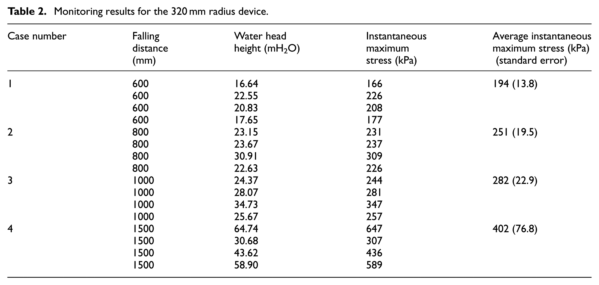
The reason for the observed deviations mostly lies in the noncontinuous nature of the rubble-mound foundation. The contact paths in a rubble-mound medium tend to be indirect and the impact force need not uniformly propagate directly downward to the monitoring device. The contact paths are also likely to change as the tamping continues. Thus, the smaller area device shows greater susceptibility to these conditions. Therefore, for the rubble size range of 10–100 kg, a larger area device is more appropriate for obtaining relatively stable results. The average tamping stresses for the four falling distances are presented in Figure 4(c) for the two monitoring devices of different radii. Tamping stress is found to increase with increased falling distance of the heavy hammer.
The error bar is used to represent one standard deviation of uncertainty, one standard error, or a certain confidence interval. It shows that the maximum standard error reached 108.3 with the monitoring results for the 100 mm radius device, whereas only 76.8 was obtained with the 320 mm radius device. Although the average tamping stresses of the monitoring devices show some deviation from the expected linear relationship, results demonstrate that the technique is feasible, particularly for the device with larger radius. Therefore, if the monitoring device is to be applied in engineering practice, a larger tamping force acting area is suggested (the radius of the larger device in this research is 320 mm).
Underwater tamping tests with wet condition
Laboratory results of testing under dry conditions verify that the proposed monitoring device provides stable and regular tamping stress values. However, further experimental studies are required to explore the nature of tamping stress propagation and ascertain whether the monitoring device can monitor the tamping stress within the complex environment of an underwater rubble bed. The field test was conducted on an incomplete underwater dock foundation about 24 m below the water surface, where the thickness of the rubble bed was 4 m. The riprap materials were in the range of 10–100 kg with a size range of 100–200 mm and had random geometric shapes according to national engineering standards. Ripraps are first packed to the natural bottom soil foundation bed under deadweight, and the initial compactness is about 0.55. The laboratory test results show that the monitoring device with larger radius provides more stable results. Hence, the 320 mm radius monitoring device was selected for this field test. A heavy hammer weighing 16.2 tons with a bottom diameter of 1.6 m was used. The ramming vessel and heavy hammer employed are shown in Figure 5(a).

Underwater field test set up: (a) ramming vessel and heavy hammer and (b) monitoring device layout.
Layout of monitoring devices
Four stress-monitoring devices with 320 mm radius were laid vertically within the rubble-mound bed each at 1 m, as shown in Figure 5(b). Before placing the monitoring devices, the surface of the riprap material was first leveled with the help of divers to ensure a level device installation for uniform monitoring results. Once a monitoring device was placed, the rubble mound was filled with additional riprap material to a thickness of 1 m using the construction vessel. The monitoring data were transferred by transmission lines laid along the shore bank. As the bottom side of the test foundation consists of natural soil layer, it can be regarded as a deformed constraint condition.
Rubble bed tamping compaction
After the four monitoring devices were installed in the vertical direction with a space of 1 m as shown in Figure 5, the ramming ship was moved to its specified location for positioning the heavy hammer directly above the monitoring devices. The heavy hammer was positioned above the top of the rubble mound for an initial falling distance of 4 m. Tamping stress values were simultaneously recorded from the four monitoring devices located within the rubble bed for a total of four tamping impacts. This initial hammer position was maintained regardless of the extent of rubble-mound settling that occurred during the tamping process.
Results of the underwater field tamping test
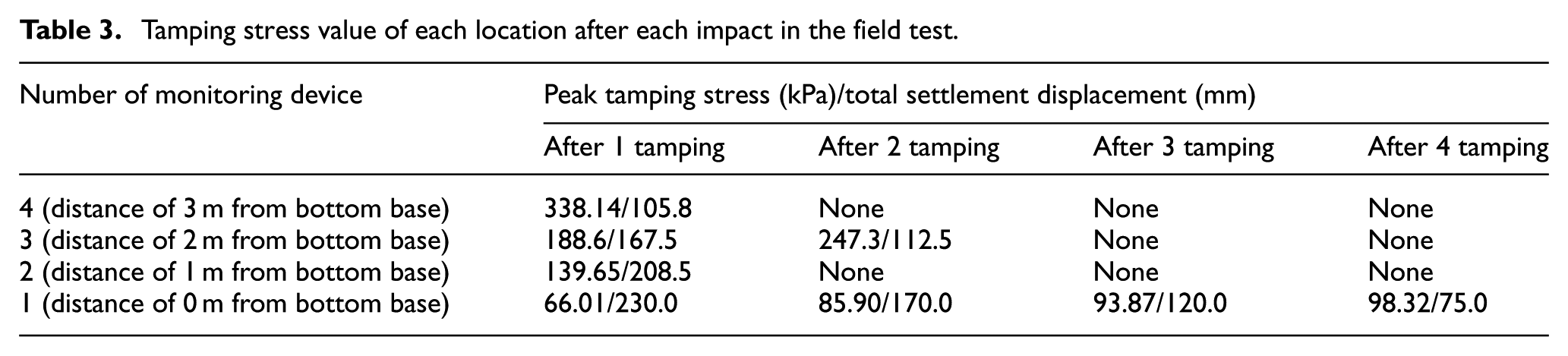
Figure 6 presents the tamping stresses obtained for the first tamping impact from the monitoring devices located at depths of (a) 1 m, (b) 2 m, (c) 3 m, and (d) 4 m from the surface of the rubble bed. The corresponding tamping stress values of each location during each tamping impact are summarized in Table 3. Figure 7(a) depicts the tamping stress values obtained for the first impact from the various monitoring devices. The data clearly indicate that the tamping stress value and the settlement decrease with an increase in distance from the top surface of the rubble bed. Moreover, an approximately logarithmic relation exists between the tamping stress (y) and the riprap material thickness (x), as shown in equation (2)


Tamping stress values obtained for the first impact from the monitoring devices located at depths of (a) 1 m, (b) 2 m, (c) 3 m, and (d) 4 m from the surface of the rubble bed.
Tamping stress value of each location after each impact in the field test.
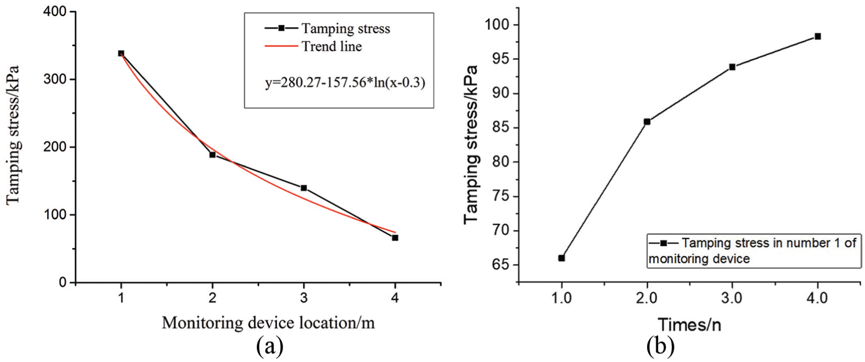
(a) Tamping stresses obtained for the first impact from the monitoring devices located at various distances from the surface of the rubble bed along with the line fit to equation (1). (b) Tamping stresses obtained for four consecutive impacts from the monitoring device located at a depth of 4 m.
As evident from Figure 7(b), the tamping stress value obtained from the monitoring device located at 4 m increases gradually with an increasing number of consecutive tamping impacts and the extent of the increase gradually reduces. One reason for this trend is that the tamping stress causes settlement of the rubble-mound bed during the heavy-hammer tamping, which ensures better propagation of the tamping force. Settlement also increases the hammer-falling distance, which indirectly increases tamping stress. However, with the repetition of the tamping impact, the rubble-mound base becomes increasingly compact, and the increase in the hammer-falling distance diminishes due to settling.
As shown in Table 3, the tamping stress is successfully monitored by all monitoring devices for the first tamping impact. However, after three tamping impacts, the 1, 2, and 3 m monitoring devices have ceased functioning due to damage. Therefore, only the monitoring device at 4 m provided continuous data. A variety of reasons can be given for the observed damage. The transmission lines which are protected by five layers of wire netting in a high-pressure pipe are unlikely to be cut during heavy-hammer tamping. Nevertheless, the said lines are susceptible to being pulled ruinously given the substantial pulling force caused by the extensive settlement of the rubble bed owing to the compaction process. The damage to the monitoring devices of the top three monitoring locations correlates with the greater settlement of the upper portion of the rubble bed relative to that of the lower rubble bed.
A comparison of the peak tamping stress with the total settlement indicates that they both exhibit a trend whereby tamping stress increases with tamping times, whereas the settlement increment of every tamping time decreases. For the four monitor points, the upper ones have greater settlement and stress in comparison to those of the lower two. The field test demonstrates that after four tampings, the compactness has reached 0.60 from the initial value of 0.55. This outcome suggests that the bearing capacity of rubble mound increases and the tamping stress can be used to reflect the foundation state. Furthermore, the said stress has the same rule as the displacement index.
Dimensional analysis of tamping stress
The additional stress right below the heavy hammer in the rubble-mound foundation can be considered to be related to the effective impact energy of the hammer, the area of action, and the depth of the measuring point. According to dimensional-analysis theory, the three basic quantities of mass, time, and length are denoted as [M], [T], and [L], respectively. The dimension of effective impact energy can be written as [ML2T−2], the dimension of action area is [L2], the dimension of measuring depth is [L], and the dimension of the additional stress of the measuring point is [ML−1T−2]. In a definite unit system, the dimensions of all physical quantities have the power product form of the basic dimensions. Thus, any additional stress has the following relationship with the effective tamping energy, the hammer tamping area, and the depth of the measuring point

where

According to the principle of dimensional analysis, when
Thus, equation (3) can be expressed as follows

where
Using the data of the model test (Table 2) and in situ underwater test (Table 3), the test stress, effective tamping energy, hammer action area, and depth of the measuring point are considered in equation (5). The nondimensional parameter

Calibration of coefficient
Using the data shown in Table 2, the only variation is the falling distance of the hammer, that is, only the effective tamper energy is changeable, and the coefficient
Thus, in the analysis of tamping rubble bed, attention should be focused on the relationship among effective compaction energy, hammer bottom area (action area), and depth of the measuring points. However, the nondimensional parameter
Discussion
The proposed stress-monitoring device used in the tamping of a rubble-mound foundation was designed in accordance with the underwater conditions of an actual engineering construction while accounting for the noncontinuous characteristics of a rubble bed. The laboratory tamping tests conducted considered different heavy-hammer falling distances and compared monitoring devices of unique surface areas. Field testing also examined the tamping stresses and relevant behaviors associated with different thicknesses of rubble bed. Consequently, the proposed monitoring device was demonstrated to be suitable for underwater and dry applications, and the experimental results conform to good engineering practice and have credibility. However, the test results also reflect some deficiencies as follows.
The proposed monitoring device was found to occasionally fail in the field tamping test. Based on the analysis presented, the reason for this occurrence was that the transmission lines were ruinously pulled out from the device due to rubble-mound settling under the high impact force of heavy-hammer tamping. Therefore, the transmission lines should be protected with steel tubes of larger diameter to protect them from being severed and pulled out.
The tamping stress values obtained in the field tests were monitored with rubble bed thicknesses of 1, 2, 3, and 4 m, which provided an approximate vertical tamping stress attenuation behavior. However, the layout was unable to measure tamping stress attenuation transversely along the rubble bed.
The proposed monitoring device is unrecoverable after conducting an underwater tamping field test. In addition, considerable time is required for confirming the tamping points because of the demands for high precision regarding the contact point of the heavy-hammer tamping.
Finally, the stability of the tamping stress data obtained with the designed stress-monitoring device maybe related to the riprap diameter, and results are expected to become increasingly unstable with increased riprap diameter. Therefore, tests using different riprap diameters and dissimilar monitoring device radii require further study.
Conclusion
Rubble mounds are a common foundation type used in practical engineering construction, and heavy-hammer compaction is commonly used to achieve the required bearing capacity. Conventional stress-monitoring instruments are of limited use because of the inherently large-scale stresses and rapid attenuation involved with heavy-hammer compaction, in addition to the underwater conditions frequently encountered. In this research, a new stress-monitoring device was designed to solve these problems, and the device performance was analyzed and verified through laboratory and field experiments. Thus, a larger size of the device radius is suggested because of the medium discreteness. Testing data demonstrate that the dynamic-load monitoring instrument can obtain tamping stress values under conditions of heavy-hammer tamping in both dry and wet conditions. Data also show the same rule in accordance with compactness and settlement, indicating that the monitoring instrument can be used to monitor the tamping process and reflect the foundation-bearing capacity.
Footnotes
Acknowledgements
We also thank Senior Engineer Bangyan Liang in CCCC Fourth Harbor Engineering Co., Ltd. for his kind help in the experiment conducted for this research.
Handling Editor: Xiaotun Qiu
Declaration of conflicting interests
The author(s) declared no potential conflicts of interest with respect to the research, authorship, and/or publication of this article.
Funding
The author(s) disclosed receipt of the following financial support for the research, authorship, and/or publication of this article: The work was supported by the National Basic Research Program of China (973 Program; Grant No. 2015CB057903), the National Natural Science Foundation of China (Grant Nos 51679071 and 51309089), the Natural Science Foundation of Jiangsu Province (Grant No. BK20171434), and the Fundamental Research Funds for the Central Universities (Grant No. 2017B20614).