
Abstract
The subject of this splitted article is the commissioning of a new application that may be part of a processing machine. Considering the example of the intermittent transport of small-sized goods, for example, chocolate bars, ideas for increasing the maximum performance are discussed. Starting from an analysis, disadvantages of a conventional motion approach are discussed, and thus, a new motion approach is presented. For realising this new motion approach, a virtual process model has to be built, which is the subject of this article. Therefore, the real process has to be abstracted, so only the main elements take attention in the modelling process. Following, important model parameters are determined and verified using virtual experiments. This finally leads to the possibility to calculate useful operating speed–dependent trajectories using the process model.
Keywords
Introduction
Modern processing machines are often characterised by the use of classical linkages in the combination of modern servo drives. For illustration purpose, an often used example of such an assembly is shown in Figure 1 which is a five-bar linkage with 2 degrees of freedom(2-DoF). The task of this linkage is to convey small-sized goods, for example, chocolate bars, with an intermittent motion. Thereby the goods are conveyed along a horizontal path with a rise to dwell motion. After the goods are transported, they stand still and the working tool of the linkage (the comb) realises a return stroke.

Intermittent transport of pieced goods along a horizontal path with a servo-driven five-bar linkage.
In the industry of producing consumer goods, a high-performance

whereby

Correlation of operating speed and performance. 2
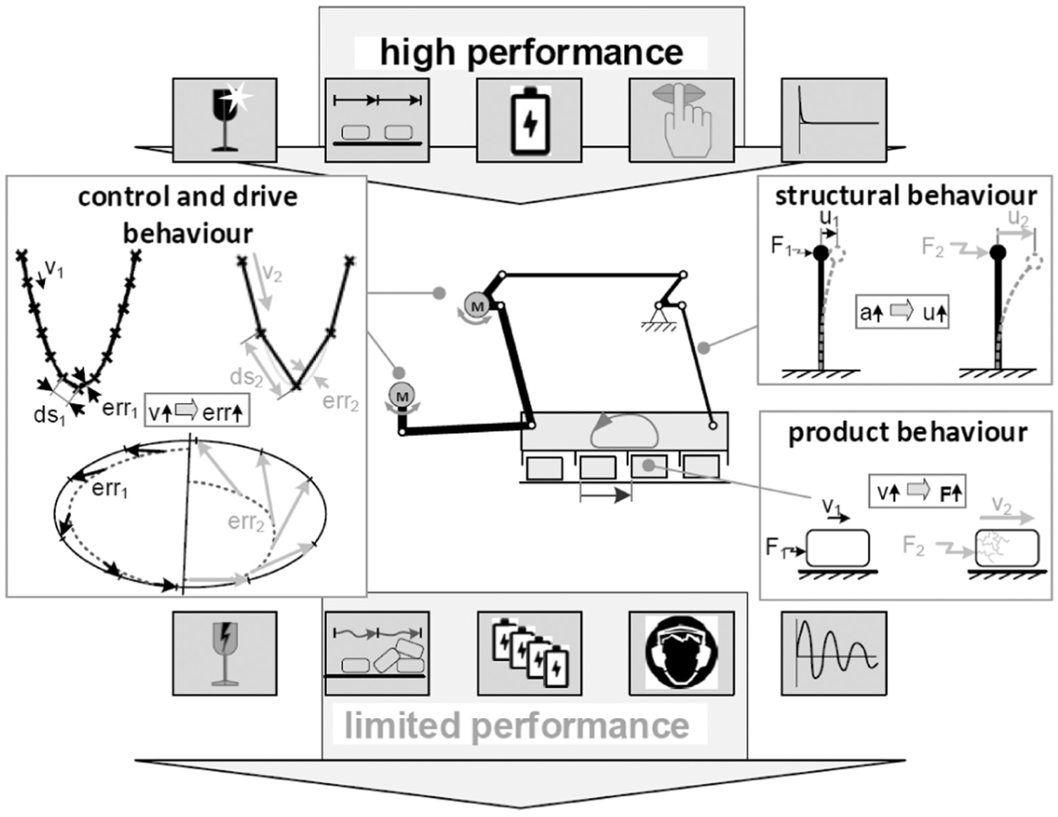
Reasons for limited performance of processing machines.
As shown, the maximum performance is, among others, limited by the control and drive behaviour of the machine. With increasing operating speed, the position error of the working tool rises and consequently the motion accuracy subsides. This results in less positioning accuracy of the product and may induce instabilities in the process behaviour. Another aspect is the increasing vibration of the mechanical structure which is caused by the progressive oscillating inertial forces in the structure. This leads to a less positioning accuracy of the working tool and rising noise, which can also be a limiting factor to the maximum performance. Eventually, the product behaviour has to be considered. With increasing operating speed, the velocity of the comb rises. This results in a higher stress for the product surface (e.g. a chocolate bar), which may breaks and so limits the maximum performance.
Thus, the maximum performance of the machine could be increased, if the motion of the working tool is changed in such a way that the product’s stress subsides. To investigate the interaction of the working tool with the product and hence determine the resulting product stress, the active unit in between them has to be observed. A possibility to realise such an observation is a computer simulation of the process as shown in literatures.3–5 Therefore, a model has to be built and verified, which finally enables one to simulate the product stress for different operating speeds, which offers the opportunity to investigate the disadvantages of the conventional realisation of the intermittent transport of pieced goods in processing machines as well as the synthesis of completely new motion approaches as described in Döring and Majschak. 6 To reveal that this model-based approach is expedient in practical manner, the simulated motions have to be tested on a test rig.
In the first part of this article, the process model building and verification is treated. An algorithm is discussed which generates process considering and operating speed–dependent motions for the working tool. The motions thus generated are experimentally investigated on a test rig in the second part of this paper, whereby necessary steps to realise the new synthesised motions with modern servo drives instead of cam follower mechanisms are presented.
Current state of technology
The conventional way of conveying pieced goods intermittently is to shove them over a slide surface using a multi-chamber transport comb, while a cam follower mechanism is used for setting the motion of the five-bar linkage. The disadvantage of this approach is that a cam only carries the information for one specific motion, which means that the motion of the working tool is principally the same for each operating speed, but always scaled to the targeted operating speed. The comb motion realised with the aid of a cam consists out of two parts. First, the product is moved from the start to the end position, while the comb rests at the beginning and the ending. Second, the comb moves back to the starting position performing a return stroke. These two parts build one motion cycle (see Figure 4(a)). Following, only the first part of the motion is considered: the transport phase. The easiest possibility for realising the transport phase is a rise to dwell motion. The corresponding basic velocity profile of the working tool and the product is shown in Figure 5(a).

Principles of (a) conventional motion and (b) new motion approach for the intermittent transport of pieced goods.

Ideal case velocity profiles of the working tool (comb) and the product over the path for (a) conventional and (b) new motion approach.
First, the boundary conditions of this realisation have to be considered. Because of product tolerances, it is not possible to realise a form closure transport. This would induce damage on the surface of the product. Thus, the gap between the two tines is greater than the product width. Therefrom, a constraint concerning the maximum reachable performance can be derived: the limitation of this motion approach is reasoned by the maximum deceleration of the comb
Following from that, a qualitative trend of the positioning error over the operating speed can be discussed (see Figure 6(a)). The product is well positioned for low operating speed because the maximum deceleration of the comb is always smaller than the friction deceleration of the slide surface. But with increase in the operating speed, the maximum deceleration of the comb gets larger than the friction-induced deceleration, and so, a positioning error of the product is expected. This positioning error increases with the operating speed quadratically. It is obvious that the positioning error gets greater than the allowed error at a critical operating speed

Trends of the product’s positioning error for (a) conventional and (b) new motion approach.
In practice, a higher maximum performance can be achieved by shifting the critical operating speed to a higher value. This can be realised by suppressing the presented detachment effect by additional friction forces on the product, for example, by increasing the friction forces with additional external loads. But this results in some disadvantages concerning the product load, for example, a higher compressive stress. Therefore, the question is whether a new motion approach is imaginable which allows a higher maximum performance with simultaneously lower product load compared to the conventional approach.
New model-based motion approach
A starting point for realising a new motion approach is the apparent disadvantage of the conventional motion approach: the unbounded free sliding of the product. The product detachment was identified as the main reason for the resulting positioning errors on higher operating speeds. But it seems to be a good idea to provoke this detachment of the product from the working tool and to use the products’ proper motion. The corresponding principle is shown in Figure 4(b). The product and the working tool are in rest and in contact at the beginning of the transport phase. Then, the product is accelerated by the comb. At the moment the comb decelerates, the product detaches from the comb and slides freely over the ground. Finally, the comb accelerates again and the second tine catches the product and decelerates it to the final position. For realising this motion approach, the basic velocity profile of the comb and the expected velocity profile of the product are shown in Figure 5(b).
Basically, two benefits of this new motion approach can be named: because of the free sliding phase of the product, the comb has to perform a smaller stroke with a constant transport distance of the process. This results from the additional gap between the two tines of the comb. The larger the gap, the lower the stroke. Other benefits are the smaller product loads. In theory, the product is only strained by the acceleration forces of the comb and the friction. Therefore, it is important that the second tine catches the product with the appropriate velocity and acceleration in the right moment. But if this transition conditions are not fulfilled, a positioning error occurs because of an impact between the product and the working tool. Thus, it is easy to see that because of the free sliding phase, the corresponding start and end velocities of this phase are not scalable to specific operating speeds. Hence, another positioning error over operating speed trend is expected than it was discussed for the current state of technology (see Figure 6(b)). If a known optimal motion for a specific operating speed is assumed, it is obvious that by scaling it to other operating speeds (regardless of whether higher or lower), a positioning error will occur.
Assuming a tolerable positioning error, there may be a range of operating speeds from
In theory, with this motion approach, the maximum performance can be increased with no limitation by the process. But there are still limits imposed by the machine, such as maximum drive torques. However, there is a lower limit for the feasible performance, since the new motion approach only works if the product detaches from the working tool. This detachment effect only occurs if the deceleration of the comb is larger than the friction-induced deceleration. For each applied motion profile, there is a specific operating speed
Summarising, the new motion approach enables one to achieve a higher maximum performance because the detachment problem of the conventional motion approach is avoided. Finally, the product’s load significantly subsides since the product is catched by the comb without any impacts. To realise this new motion approach, two steps are necessary: First of all, an algorithm has to be designed which allows the calculation of an optimal motion for a given operating speed. Because of the multiple process parameters, which influence the yet unknown optimal trajectory, a process model has to be built which will be used in a simulation. The results of the simulation will be an important part within the algorithm. Therein, the model is used to calculate different optimal motions for the working tool. Finally, it will be proven that this new process does not work with a single motion profile. Hence, this new approach is not suitable for traditional cam follower mechanisms, but for modern servo drives it allows the execution of speed-dependent motions.
Building the process model
In order to create the process model, an abstraction of the process is first necessary, so only the main effects and elements will take attention in the simulation. Therefore, the main interacting elements of the process are chosen (see Figure 7). The system to be simulated consists of the product, two slide surfaces and a quarter of the comb. Therefore, the abstracted comb is represented by 2 × 2 = 4 tines which are necessary to simulate one motion cycle. For implementing the model in a multi-body simulation, the joints between the local frames of the different elements (bodies) regarding the world frame

Main elements of the system to be simulated which have to be part of the model.
For realisation of the simulation, the model is implemented in MATLAB/Simulink and the Multibody Toolbox. This allows the easy implementation of three-dimensional (3D) bodies including their mass and inertia definitions. To initialise the model, the toolbox provides an import function for computer-aided design (CAD) parts with their specific rigid frames. By linking the body frames as described, as well as setting the initial positions, the model is fully built. While the simulation is running, the multibody equations are automatically solved, so the motions can be integrated accordingly. To realise the contact interaction, the Contact Forces Library is used. It allows the contact detection and calculation with the help of a Voigt–Kelvin model (see Figure 8) as it is used in the discrete element method (DEM). By the calculation of elastic impacts as well as frictions, it becomes possible to simulate rigid body interactions. The method was originally used to simulate molecular systems.
8
Therefore, spheres are still the means of choice because their contact is easy to detect by the calculated intersection

Principle of contact detection and normal force calculation in DEM with a Voigt–Kelvin model.
If a contact is detected (

This law can be used for simple applications, for example, contacts with small relative velocities. The disadvantage of this law is the fact that the coefficient of restitution

In practice, the coefficient of restitution is not constant because impacts are mostly related with plastic deformation, so with increasing relative velocity, the ratio of free kinetic energy to inner deformation energy changes. To describe this contact behaviour, the HertzianSpring-Dashpot model (HSD) was constructed and named after Hertz
10
(see equation (4)). Because of the parameters
Besides the calculation of normal forces

There are multiple ways to define the coefficient of friction

Possibilities of friction definition with respect to the relative velocity.
In the Contact Forces Library, case B is provided. A further advantage of this definition is the possibility to redefine the function
To implement the process model, all bodies are prepared in an external CAD system, so the import can be realised by simply setting the initial position as well as the density, hence the mass and the inertia tensor can be derived. For realising the body interactions, simple contact cases of the Contact Forces Library are used. As seen in Figure 10, the contact between the product and the sliding surface is implemented as a sphere-to-plane contact. The corresponding contact law can only be set after appropriate tests at the real active unit. For setting the size of the sphere radii


Modelling the contact between product and slide surface.
After these steps, the model is set up, and so, the first step of the simulation is done. While implementing the model, the necessary parameters were discussed, especially the contact parameters are decisive for the significance of the model. Therefore, the model has to be verified regarding these parameters.
Model verification
As described in Bossel 14 and Sargent, 15 the aim of the model verification is to check whether the model has been built right and thus works physically correct or not. One possibility to realise this is to check whether the model parameters induce the expected physical behaviour of the system. By comparing the expected (theoretical) model behaviour with the simulated behaviour, a quantification of the model goodness can be determined. Therefore, the main model parameters have to be selected and checked by executing virtual experiments. Following from the model building and the simulation task, the parameters that must be checked are the ones which are related to the active unit. So, the coefficients of restitution, static friction and kinetic friction are important. After a successful verification, the model goodness concerning the physical correctness can be claimed. In Malone and Xu, 16 experiments for the validation of a DEM model are described which can be used virtually to verify the model.
To evaluate the coefficient of static friction, the experiment of the inclined plane is consulted (Figure 11(a)). For a given coefficient of static friction


Experiment for determining the coefficient of static friction: (a) experiment and (b) product velocity.
For verification, the model parameter
To verify the coefficient of kinetic friction, an impact experiment is implemented. The product is in rest on a slide surface and gets an impact with a specific collision velocity

whereby

Results of the investigation of the coefficient of kinetic friction.
The coefficient of restitution is a parameter which cannot be set directly in the model. Thus, the elastic behaviour of a contact, which results out of the coefficient of restitution, is determined by the coefficients of the contact law

whereby

In Figure 13, the results of this experiment for different collision velocities are shown. Because of the assumed constant restitution behaviour, the expected product velocity is linear with respect to the collision velocity. As can be seen, the relative error of the simulated results related to the theoretical value (the given parameter
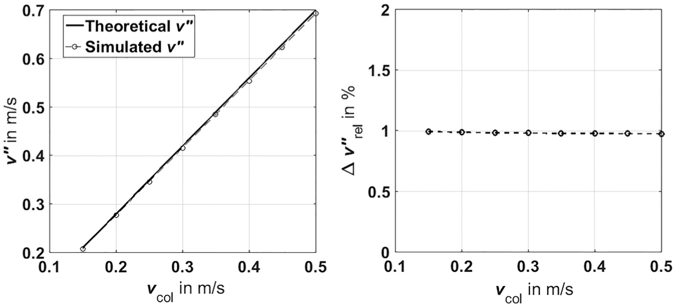
Results of the investigation of the coefficient of restitution.
Eventually, the verification of the model was successful. All parameters were tested in virtual experiments, while the results are satisfying. It is expected that the calculated errors resulting from the model are smaller than the inaccuracy of measurements which will occur while setting the real model parameters. Thus, the model can now be tested concerning the usability for trajectory planning within the new motion approach.
Model-based trajectory planning
For realising the new model-based motion approach, the necessary trajectory has to be planned. Therefore, a distinction of the path and the related velocity profile seems to be expedient. Because of the horizontal two-dimensional (2D) comb motion, the path is given by a line segment with the length of the comb distance. Much more interesting is the associated velocity profile of the motion. To fulfil the new motion approach, the profile has to have a certain shape. Therefore, the schematic profile of the velocity profile is shown in Figure 14.

Schematic velocity profile of the working tool with adjustable parameters.
For each considered operating speed, the transportation time
t = 0: at the beginning of the motion, the comb and the product are in rest, so the velocity and the acceleration are zero.
t = t1: this time is characterised by the beginning of the free sliding phase of the product. So, the acceleration
t = t2: at this time, the comb has to do a reversal acceleration motion, so it stops slowing down and starts to accelerate at a specific velocity value
t = t3: after the product slides freely between the comb gap, it has to get catched by the next tine. Thus, the comb has to have the same velocity and acceleration as the product to avoid an impact and realises a smooth catching.
t = ttr: at the end of the transport phase, the comb and the product are in rest.
To connect the specific events of the velocity profile, it seems to be useful to use a quintic function, 19 which has six free adjustable parameters, so all velocity and acceleration constraints are included and also a jerk continuity can be reached

For the synthesis of the complete velocity profile, the adjustable velocity and acceleration parameters for the three events have to be set. Therefore, an iterative algorithm was designed, which functionality can be seen in Figure 15. Starting with the initial values and the fixed values given by the reached operating speed, the four velocity segments are calculated and merged to the complete velocity profile. To meet the condition that the path ends in the moment

Iterative algorithm for calculating optimal velocity profiles.
The algorithm represents an iteratively working solver for a nonlinear system of equations. It is implemented with the gradient-based trust region algorithm 20 which minimises the residues. Therefore, it is important to choose valid initial values, so converge can be reached. With the help of the algorithm and the product model, it is possible to create an optimal velocity profile for each given operating speed. If at least two profiles are given, a characteristic map can be generated by interpolating the velocity profiles between them. For a free (but useful) choice of parameters, an exemplarily characteristic map is shown in Figure 16.

Characteristic map of the velocity profiles for different operating speeds
As it can be seen, the shape of the velocity profiles for each operating speed is different. This prove the necessary specification of different optimal motions for different given operating speeds
Summary
In this article, the maximum performance-limiting factors of a processing machine were discussed. As an example, the intermittent transport of pieced goods was observed and the disadvantages were illustrated. Therefrom, a new motion approach for the process was derived, which theoretically helps to increase the maximum machine performance. To realise this new approach, a process model with the help of a 3D multi-body simulation in addition with the appropriate contact realisation was built and verified. This process model was then used in an algorithm which calculates operating speed–dependent velocity profiles. These profiles can be assembled to a characteristic map, which is necessary to successfully realise the process for different operating speeds.
In the second part of this article, the model will be validated. This means that the model parameters are adjusted to the real active unit behaviour. This allows the calculation of optimal trajectories for the new motion approach. In addition, the sucess of these optimal motions is evaluated on a test rig, whereby the implementation of the speed dependency will be a main part. Furthermore, expedient possibilities of process observation and control will be discussed.
Footnotes
Handling Editor: Yong Chen
Declaration of conflicting interests
The author(s) declared no potential conflicts of interest with respect to the research, authorship and/or publication of this article.
Funding
The author(s) disclosed receipt of the following financial support for the research, authorship and/or publication of this article: This work was supported by the DFG (German Research Foundation) under the grant numbers GR 1458/ 47-2 and MA 4550/3-2. Furthermore, the publishing of this article is supported by the German Research Foundation and the Open Access Publication Funds of the TU Dresden.