
Abstract
Marine power rear transmission system is a constant power system under specific working condition, which relies on alternating meshing gears to transfer the movement and torque. It is difficult to accurately determine the actual thermal stress and thermal deformation for time-varying distribution using the traditional methods. Elastic structural mechanics modeling and method details of thermal expansion deformation are presented and analyzed. Both the actual reflection thermoelastic contact condition for meshing gears and the coupling effect results of the practical loading process of marine power rear transmission system carried out on alternating meshing gear surfaces are also detailed. In this article, the changes in gear meshing angles of several key meshing positions are presented. The 16 meshing positions of contact stresses and loaded deformation approach are analytically evaluated in terms of the rotation range of driving spur gear (35°) and driving helical gear (36°). The purpose of this study is to confirm the significant stress concentration areas of gear meshing in and meshing out and to obtain that the deformation amounts of gear meshing impact positions within selected zones. The aim of this article is to reach gear deformation on the basis of theoretical conception.
Keywords
Introduction
Gears subjected to large loading and high speeds are very often used in marine power rear transmission system; regularly in the process of alternating meshing, thermal expansion elastic deformation occurs.1,2 When the teeth profile is deviated from the standard involute, the strong impact and vibration may occur in the meshing gear process.3,4 A great deal of studies5,6 have considered that the size and distribution of contact pressure on teeth surface would directly affect the frictional heat flow on meshing teeth surface and made a decisive influence on the temperature of gear body. Moreover, some researchers7,8 have pointed out that the temperature field, stress field, and displacement field of gears should be mutually coupled. Therefore, it is important to study the thermomechanical coupled analysis of marine gears under large loading and high speed of transmission system.9,10
Some studies11,12 are proved that coupled field finite element analysis processes have to be formulated based on the interaction and mutual coupling of two or more physical fields, such as thermo-structural, thermo-electrification, and thermo-magnetic couplings. It is important when the engineering structure is heated or cooled, and then, expansion or contraction may occur.13,14 If the expansion and contraction levels of various parts of the structure are different, the expansion and contraction of the structure are limited. Then, thermal stresses are generated.15,16 To find out the maximum time point of temperature variation gradient and the node temperature at this point in this time is a fundamental feature of the structural contact stress analysis. 17 Thermal expansion elastic deformation and structural contact stress are considered simultaneously.18,19 The models of structural contact analysis and thermal expansion elastic deformation have similar meshing partitions to ensure that the thermal and structural elements have the same number of nodes. 20 In marine gear contact analysis, the contact stress of multiple meshing positions should be calculated in order to obtain the force distributions on gear pair in the entire meshing process.
The thermal expansion elastic deformation analysis would be transformed into structural contact analysis and is attractive for applications in warship system engineering. In this study, a pair of meshing gear is simplified into a spring–damper–mass system and a linear analysis. Several typical examples of thermal coupling analysis from spur gears and helical gears are presented.
Analysis model and numerical simulation
Analysis model of marine power rear transmission system
The structural coupling system of marine cylindrical gear is obtained by simplifying power rear transmission system into the elastic system affected by thermal expansion and thermal deformation. Figure 1 presents the model of gear contact coupling to follow the influence of the thermal expansion and thermal deformation during the meshing process. The basic assumptions of the conception are listed as follows:
High rigidity contributes to a mechanical strength support for power rear transmission system.
Contacts with sliding and rolling movements between meshing gear teeth surface. 21
The meshing reactions between gear teeth surface always act on meshing line. 22

Coupling model of MPRT system with thermal expansion elastic deformation.
As illustrated in Figure 1, Tx and Ty denote the stiffness coefficients of meshing thermal expansion of driving and driven gears, respectively. Ks and Kg are the elastic deformation coefficients of driving and driven gears, respectively. Ms and Mg are the driving and driven gear meshing damping coefficients, respectively. Es is the gear meshing impact coefficient. Qp and Qg are the driving and driven gear angular positions related to the torques. Tp and T are the torques of driving and driven gears, respectively. Ip and I are the inertia moments of driving and driven gears. Q is the gear meshing torque. Rp and Rg are the radii of driving and driven gears, respectively. With respect to a very small value of the inelastic deformation between gear meshing teeth, the expression employed in the model can be written as follows

In order to reach the structure contact characteristics of marine power rear transmission (MPRT) system, using generalized coordinates x1 = Ms or Mg and x2 = Q − Qg, equation (1) should be presented in the following form

Numerical simulation of MPRT system
Considering the thermal expansion stiffness coefficient of driving gear meshing under the same loading sharing excitation, the influence of gear pair impact of coupling contact is very significant. In this article, the Runge–Kutta method 23 with five- to six-order adaptive step sizes are used to solve equation (2). The numerical solution of meshing gear coupling contact of MPRT system is presented. Table 1 presents the parameters of herringbone gears. When Tx = 0.02 as shown in Figure 2(a) and Tx = 0.07 as illustrated in Figure 2(b), Tx = 0.12 as expressed in Figure 2(c).
The parameters of herringbone gear pairs.


(a) Input contact characteristics numerical simulation
Teeth surface structural contact characteristics of meshing region from the whole meshing cycle can be reached using the numerical analysis. As illustrated in Figure 2, with the increase in meshing thermal expansion stiffness coefficient, the convergence speed of teeth surface meshing phase is decreased. This indicates that meshing thermal expansion stiffness coefficient could not effectively suppress contact impact, but can improve the instability of MPRT system. Therefore, it is crucial to analyze marine meshing gear thermodynamic coupling of power rear transmission system.
Thermomechanical coupled analysis of MPRT system
The structural contact analysis units should be rebuilt after conversion into thermal structure by the use of the model. Selection of the structural units’ nodes is done with respect to the temperature field elements’ nodes. It enabled to define structural material properties and add thermal expansion coefficients in this analysis. Marine gear alternate meshing area division of power rear transmission system is shown in Figure 3.

Marine gear alternate meshing area division of power rear system.
Thermomechanical coupled analysis of spur gear
As illustrated in Figure 4, the thermal expansion stiffness coefficient of the driving gear was considered to evaluate the performance of gear teeth surface coupling. The range for the rotation angle was from 0° to 35°. Selected values of the angle were employed to follow the gear behavior at 16 meshing positions. The parameters of spur gears are listed in Table 2.

(a) Position 1 meshed-in impact point, rotation angle is 1. (b) Position 2 double-tooth meshing transition to single-tooth C point. (c) Position 3 single-tooth meshing area, rotation angle is 18.5. (d) Position 4 single-tooth meshing transition to doubleteeth D point. (e) Position 5 meshed-out impact point, rotation angle is 35°.
The parameters of spur gear pairs.

The values of contact thermal stress of the double-teeth surface meshing coupled were increased rapidly and achieved the alternating meshing steady state of mutual conversion. In the initial stage of gears meshed, the thermal stress values at position 1 were greater than those for the other cases considered. Therefore, the influence of meshed gears during impact at position 1 for the thermomechanical coupled contact is most obvious (Figure 4(a)).
The elastic deformation and damping coefficients of the gear meshing conversion progress of double teeth to single tooth are considered (Figure 4(b)). The values of contact thermal stress of the alternating meshing steady state of mutual conversion are presented. These magnitude values at position 2 were smaller.
The values of contact thermal stress of the single-tooth meshing steady state are analyzed. The results at position 3 were bigger than the values for position 2. The values of contact thermal stress of the double teeth and above alternating meshing area are presented in Figure 4(d). The data at position 3 reached higher values than at position 4. However, the effect of thermoelastic deformation of position 4 is more prominent.
As shown in Figure 4(e), the values of contact thermal stress of position 5 are greater than those noticed for positions 2 and 4. The effect of thermoelastic deformation of position 4 is also more prominent.
Therefore, meshed-in and meshed-in impacts and thermal expansion deformations are modern approaches for the problem considered. For key point D, where the meshing area of single tooth converts into that of double teeth and above, this position is analyzed in detail in the following manner. As illustrated in Figure 5, the value of thermal contact stress changes significantly and has the maximum value of 761.6 MPa.
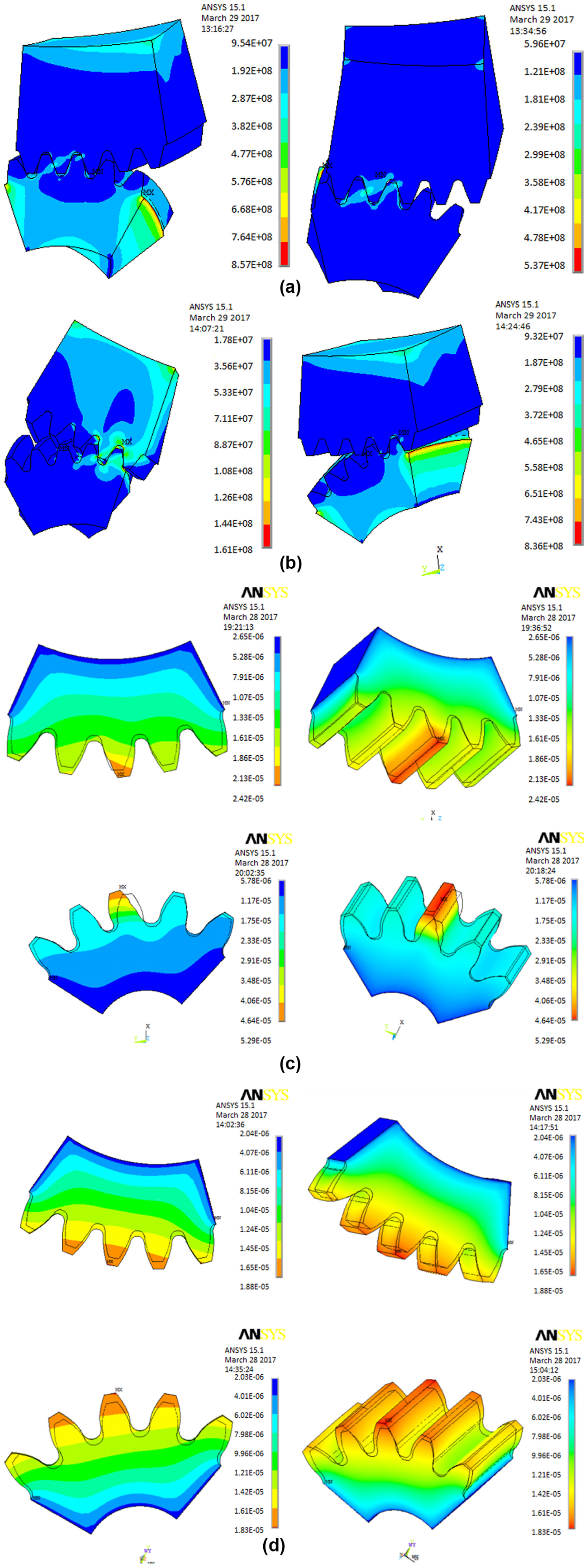
(a) Thermoelastic deformation and elastic contact stress. (b) Thermoelastic deformation and elastic contact stress. (c) Driven gear thermal expansion deformation. (d) Driving gear thermal expansion elastic deformation.
When the single-tooth meshing is just converted into the double-teeth meshing, the calculation of thermal expansion deformation of driven gear can be proposed (Figure 5(a)). When a pair of single teeth is ready to end the meshed-out, the calculation of thermal expansion elastic deformation of driving gear is created (Figure 5(b)). It is more clearly seen in Figure 5(c) and (d) that the thermal expansion elastic deformation is enlarged along the tooth height values and reached a maximum value of 51.3 μm.
Thermomechanical coupled analysis of helical gear
Using the same operating conditions, the influence of the elastic deformation and damping coefficients of the alternating meshing steady state of mutual conversion, the contact stress of thermoelastic coupling of helical gear teeth surface was analyzed (Figure 6). The angle of rotation was from 0° to 36° and nine meshing positions were followed.

(a) Position 1: meshing-in impact point, rotation angle is 1, meshing joint node number is 224, and joint node number of distance from addendum is 0. (b) Position 2: double-teeth meshing transition to single-tooth meshing C point, rotation angle is 16.5, meshing joint node number is 257, and joint node number of distance from addendum is 35. (c) Position 3: single-tooth meshing area, rotation angle is 18.5, meshing joint node number is 254, and joint node number of distance from addendum is 38. (d) Position 4: single-tooth meshing transition to double-teeth meshing D point, rotation angle is 21.5, meshing joint node number is 250, and joint node number of distance from addendum is 42. (e) Position 5: meshing-out impact point, rotation angle is 36, meshing joint node number is 235, and joint node number of distance from addendum is 56, and the contact stress rises when the gear is about to end meshing.
As illustrated in Figure 6, the left figures are the nephogram of thermodynamically coupled deformation and the right figures are the nephogram of elastic deformation. As it can be seen, the contact thermal stress of the addenda of driving and driven gears with being meshed-in and meshed-out in alternate meshing area is concerned. Considering the mutual influence of adjacent teeth, the finite element analysis models of five pairs of helical gear teeth surfaces are presented.
Taking into account the thermo-structural coupling calculation through the analysis models, the contact coupled thermal stress of the helical gear at each position along meshing line under the influence of thermal expansion elastic deformation was obtained (Figure 7).

Contact stress on target surfaces: (a) meshing positions 1, 2, and 3; (b) meshing positions 4, 5, and 6; and (c) meshing positions 7, 9, and 11.
The trend of contact stress is close to the value of 203 MPa, which creates an opposite conclusion. BC and DE segments are in alternate position of single-tooth meshing area and double-teeth meshing area, where the contact stress changes significantly. When meshing gears are in the CD section, the contact stress of single tooth is much bigger than that of double teeth (Figure 8).

Contact stress of helical gears along meshing line on points.
As can be observed from Figure 9(a) and (b), distribution of thermoelastic deformation at meshing point and thermal expansion on the teeth surface are clearly evidenced. The value of thermal expansion elastic deformation is not uniform and has the maximum value of 233.4 μm.

(a) Helical gear elastic deformation amount and (b) helical gear thermoelastic deformation amount.
In two or three pair’s teeth and the alternate meshing process of helical gears, a certain amount of thermal expansion and elastic deformation at meshing contact zones appears. Worth to notice that meshing with other teeth will not produce the influence of thermal elastic deformation and thermal expansion. It is necessary to propose conception on thermal expansion and elastic deformation during gear meshing of the MPRT system.
Conclusion
Thermal expansion deformation is difficult to study in the process of the MPRT system gear alternating meshing. Typical theory does not enable to perform correct calculations, unless certain assumptions are used. When meshing gears lose the contact, then the maximum stress occurs at teeth root of driving gear (driven gear teeth tip). To avoid this effect, dedendum or addendum needs to be modified.
Thermal deformation causes expansion effect in meshing teeth, leading to increase in tooth thickness and outward expansion of working teeth, which compensates for teeth deformation and reduces contact area deformation. During single-tooth meshing cycle, teeth contact stress varies with meshing position. For alternate position of single-tooth meshing area and double-teeth meshing area, significant changes for meshing contact stress occur. The thermal expansion and elastic deformation are important features of the MPRT system and may be evaluated applying numerical approaches.
Footnotes
Acknowledgements
The authors gratefully acknowledge the support from the Harbin Institute of Technology (HIT) as well as the Harbin University of Science and Technology (HUST).
Handling Editor: Michal Kuciej
Declaration of conflicting interests
The author(s) declared no potential conflicts of interest with respect to the research, authorship, and/or publication of this article.
Funding
The author(s) disclosed receipt of the following financial support for the research, authorship, and/or publication of this article: This work is supported by pre-research project in Ship Research Institute of China (grant no. MAPT 27042016). Part of simulation works were performed on Dawning-TC5000 system in Supercomputing Center, Shenzhen Institutes of Advanced Technology, CAS, China.