
Abstract
Gantry systems in which two linear motors are used to drive a single axis provide flexible and efficient solutions for a wide range of material handling applications. It is an important issue to find a way to drive the parallel stage to achieve a synchronous motion effectively and precisely. In this research, the proportional–integral–derivative–type fuzzy controller structure is presented for precision trajectory tracking control in synchronized XY motion gantry stage system. Three proportional–integral–derivative–type fuzzy controllers are designed for each axis, and the complete membership functions and rule table are developed to fulfill the better tracking capability. The controller parameters, which include the scaling factor of fuzzy rules and proportional–integral structures, are searched using the cross-mixing global artificial bee colony algorithm. The algorithm can optimize these parameters based on the integral of the time-weighted absolute error criterion. MATLAB system identification tool is used to find the equivalent coupled transfer functions of the gantry system. The proposed cross-mixing global artificial bee colony algorithm is utilized to offer the better convergence speed and avoid the local optimal solution in the searching process. The simulation results and experimental results on star and circle reference contours are presented to show that the proposed cross-mixing global artificial bee colony–based fuzzy controller indeed accomplish the better tracking performances in motion control application.
Keywords
Introduction
The precision XY gantry motion control1–4 is widely used for many industry apparatuses, such as various machine tools, computer numerical control (CNC) machine, printed circuit board, laser-/water-jet cutting machines, loading and unloading machine, pick and place, and positioning stages. The gantry system can be applied in the applications which require carrying a heavy load in multiple axes or need an open space below the area of motion. Also, it needs to provide the properties of high-dynamic and high-precision Cartesian movement. Precision motion of multiple axes stage that it is controlled in synchronous manner considered an important and essential problem for modern control system. A high-resolution and high-performance servo system that provides excellent gantry control and accurate positioning control is the basic and critical requirement.
The synchronous motion techniques1–4 can be categorized as master–slave motion control method, cross-coupling technique, biaxial cross-coupled technique, and relative dynamic stiffness motion control method. The synchronous control scheme for a single-axis stage driven by dual parallel ball screws motors was proposed. 5 A closed-loop identification technique for the coupled and decoupled models was presented, and the synchronous proportional (P) compensator was incorporated in the position loop. With the advantages of high force density, rapid dynamic response, low thermal noise, and a simple structure, the permanent magnet linear synchronous motor (PMLSM) 6 was applied for the motion control. The linear motor can directly transmit to the payload without the mechanical interface such as gears and lead screw. According to the above description, it is beneficial to drive the stage of a large single-feed axis with two linear motors which are arranged in parallel to provide a joint thrust in the same direction. This would significantly increase the system rigidity and overall thrust for driving the stage. The parallel synchronous control scheme7,8 was presented to build two-port model of linear motor–driven gantry system. The authors designed the proportional–integral (PI)-type synchronous compensator to verify the positioning accuracy. However, the conventional PI control is not suitable to tackle many problems such as steady state error, speed changes, and load disturbances.
Several advance intelligent and adaptive control methods, such as fuzzy method,9–12 neural network,9,13–15 particle swarm optimization (PSO), 16 and artificial bee colony (ABC)12,16,17 algorithm, were proposed. A digital signal processor (DSP)-based cross-coupled intelligent complementary sliding mode control (ICSMC) system 14 was presented for the synchronous control of a dual linear motor servo system in a gantry position stage. The Takagi–Sugeno–Kang (TSK)–type fuzzy neural network (FNN) estimator with superior approximated ability was applied to estimate the unknown lumped uncertainty online. The convergence of both the position tracking and synchronous errors of the dual linear motor servo system were obtained. Using the global optimization method, it has been made possible to search the optimal values of the design parameters systematically. The effective proportional–integral–derivative–fuzzy logic controllers (PID-FLC) structure10,11 was developed to control the multi-input multi-output (MIMO) active magnetic bearing system. The controller design parameters are optimized using genetic algorithms (GA), PSO, and gray wolf optimizer (GWO) meta-heuristic optimization algorithms. This optimal fuzzy controller can provide remarkably superior performances in MIMO system.
The fuzzy-based PID controller design 12 of the electrolyzer was presented for microgrid stabilization. The bee colony optimization is used to tune the scale factors, membership functions (MFs), and control rules to obtain the superior stabilizing effect and high robustness. The main advantages of the ABC algorithm over other optimization methods for solving optimization are simplicity, high flexibility, strong robustness,17–20 few control parameters, ease of combination with other methods, and fast convergence on both exploration and exploitation. ABC method is considered as highly flexible, since it only requires two control parameters of maximum cycle number and colony size. Therefore, adding and removing bees can be done without need to reinitialize the algorithm.
In this research, the PID-type fuzzy controller structure is proposed for precision trajectory tracking control in synchronized XY motion gantry stage system. Two PMLSMs, which are mounted on two parallel rails in the Y-direction, move simultaneously a beam. The head assembly on the beam moves in the X-direction. The controller parameters are searched using cross-mixing global artificial bee colony algorithm (CGABC). The algorithm searches the optimized parameters based on the integral of the time-weighted absolute error (ITAE) criterion. MATLAB system identification tool is used to find the transfer function of the system according to the superposition theorem. The proposed CGABC method can not only converge in a short time but also avoid the local optimum solution in the searching process. The simulation results and experimental results on star and circle reference contours are presented to show that the proposed CGABC-based controller indeed accomplish the better the tracking performances.
System model
PMLSM model
The typical mathematical modeling of the PMLSM2,6,15 can be derived here. Figure 1 shows the equivalent block diagram of PMLSM system, and the vector control method is applied for the XY gantry stage. The d–q control voltages2,6 is given as
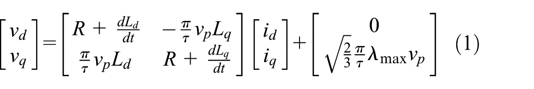
where

The equivalent model of PMLSM system.
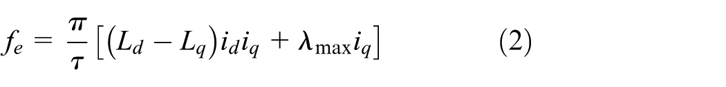
The mechanical dynamic equation is expressed as

where M denotes the mass of the motion table, B denotes the viscous friction coefficient, x is the stage displacement, and

where

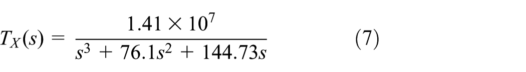
Transfer function of the drive system between the voltage command
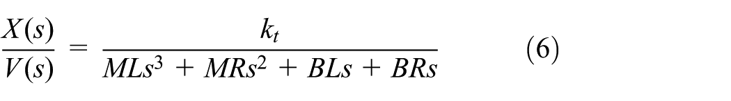
where
Proposed system and identification method
Figure 2 shows the experimental gantry type platform for our motion control application. The controlled system consists of one linear servo mechanism in X-axis, and two parallel linear servo motors in the Y-axis with mechanical coupling. The position information of each axis can be measured by optical encoder sensors. Both control and feedback signals are manipulated by a D/A converter card and one encoder card. It is shown the gantry type control system for XY stage, which is actuated by a PWM digital servo driver controller COR-5/230 from Elmo motion company, and three CPC-CLS-PM4 PMLSMs manufactured by Chieftek Precision Co., Ltd. The specifications of continuous force, peak force, continuous current, and magnetic pole pitch of the controlled PMLSM motor are 18.5 N, 74 N, 5 A, and 15 mm, respectively. The optical shaft encoder is used to measure the position information, and the resolution of the encoders is set to 1 μm. Our system is designed using a personal computer (PC)-based controller with sampling rate of 1 kHz. The stage consists of a 225 mm effective travel for X-axis, and two 225 mm effective travels for Y-axis. In the Y-axis, two parallel PMLSM mechanisms with mechanical coupling are considered here.

The experimental XY gantry platform system.
Figure 3 shows the equivalent block diagram of two-axis XY gantry platform. The coupled twin-parallel linear servo mechanism is adopted to model the Y-axis structure.7,8 First, the master Y-axis linear motor is fed with a unit step voltage command
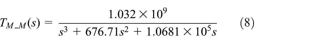


where

The equivalent block diagram of two-axis XY gantry platform.

Block diagram of mathematical identification model architecture.
Proposed PID-type fuzzy controller
The PID-type fuzzy controller is designed to actuate the PMLSM for precision motion control. Figure 5(a) shows the structure of our proposed fuzzy controller. The parameters

where

(a) Block diagram of fuzzy controller and (b) the proposed PID-type fuzzy control XY gantry system.
The inputs and outputs of the fuzzy inference system 9 are transformed into five linguistic variables; they are NB (negative big), NS (negative small), Z (zero), PS (positive small), and PB (positive big). The complete MFs and rule table for fuzzy controllers are shown in Figure 6.When the error variables become large, the fuzzy outputs can increase adaptively and perform rapid tracking performance. The triangular-shaped MFs for the input variables are chosen, and singleton function for output variable is shown in Figure 6. The inference mechanism based on the Mamdani algorithm 9 is utilized here. Fuzzy rule tables providing the knowledge base to the controller are illustrated in Figure 6(d). These rules are expressed as

with

where

where

Membership functions and rule table for fuzzy logic controllers.
The objective function
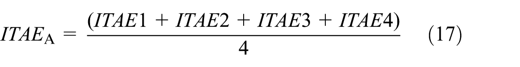
Based on the identification model of the XY gantry system, the developed fuzzy synchronous control architecture is shown in Figure 5(b). It consists of the two subsystems, those are (a) X-axis fuzzy controller for one linear servo motor and (b) master and slave Y-axis fuzzy controllers for two parallel linear servo motors. The objective of the modeling and control is to minimize the tracking error for each axis and synchronous error between the two parallel axes. The fitness function to be minimized is the integral of time-weighted absolute error (ITAE) performance criterion. 11 The ITAE criterion is defined as

where
with

where
ABC algorithm
ABC algorithm17,18 mimics the food foraging behavior of swarms of honey bee. ABC method is an optimization algorithm inspired by the nature of bees foraging behavior to find the best nectar. The way the bees transmit information is through the dancing of the body, which is called waggle dance. Honey bees can apply some mechanisms like waggle dance to find food source and search new ones. The ABC consists of three groups of bees to search foods, which are the employed bees, the onlookers, and the scouts. The employed bees search a food source within the neighborhood of the food source in their memory. The onlooker can select good food sources from those found by the employed bees, and they also search the foods around the selected food source. The scouts are the explorers of the colony to find the new of food sources. Because the bees do not have any nectar information and experience, all bees are the role of scout bees at beginning. Let
where

where

where
The employed bees and onlooker bees are replaced by scout bees to find the new nectar. The update equation of scout bee is as follows

where
CGABC algorithm
ABC continues to attract the interest of researchers from various fields, and it can result in several modification or enhancement to the basic algorithm. The researches have been conducted, and new versions have been released for ABC algorithm in order to improve its convergence property, success rate, accuracy, and exploration capability. The guided artificial bee colony (GABC) algorithm 18 is proposed to improve the exploitation and take the information of the global best solution in the search process. The update equation is described as follows

where the third term
The cross operation is added in the CGABC method
18
to improve both exploitation and exploration. First, a uniform random number

where
where
The design procedure
The CGABC optimization technique is used due to its requirement for less number of adjustable parameters and its capability to produce global optimal solutions. The parameters of the scaling factors in fuzzy controller are trained using ABC optimization algorithm. Figure 7 shows the flowchart of the proposed design procedure. The overall CGABC algorithm of the proposed PID-type fuzzy control for solving the trajectory tracking problem is as follows:
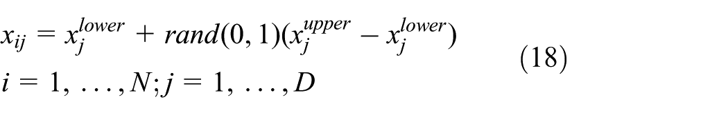
Step 1: Initialize food sources and select parameters for the CGABC algorithm;
Step 2: Derive the equivalent PMLSM model and identify the gantry system model with mechanical coupling effect by equations (7)–(11);
Step 3: Design the fuzzy MFs, rule tables, and scaling factors
Step 4: Perform the specific contour tracking for XY gantry system and compute the
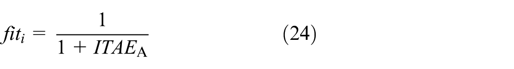
Step 5: Calculate the fitness function by equation (24), set the initial food sources as the best solution, and set the iteration counter to one;
Step 6: Determine the new position (scaling factors) for employed bees by equation (23);
Step 7: Perform the specific contour tracking for XY gantry system and computed the
Step 8: Calculate the fitness function corresponding to the new position of the employed bee;
Step 9: Compare the new value of the fitness function with the best one before and replace the new position if the new fitness function is the smaller one;
Step 10: If not all onlooker bees are distributed to food sources, the new position is updated by onlooker bee and return to Step 7;
Step 11: Determine unimproved food sources when the number of Limit is exceeded;
Step 12: If the food sources are not improved further, the scout bee is reinitialized to find the food source. The contour tracking is performed, and the fitness function value is computed;
Step 13: Update the best food source position and the corresponding fitness function value;
Step 14: If the maximum number of iterations is not reached, increase the iteration counter and return to Step 6.

The flowchart of our proposed design procedure.
Experimental results
In this research, two contour shapes are compared, that is, (a) star contour and (d) circular contour, to evaluate the performance of the proposed biaxial motion control system. We select a control sampling frequency of 1 kHz for the trajectory tracking loop. The contour trajectories are depicted as follows:
1. Star contour—the star contour includes five segments as shown in Figure 8(a). The trajectories a–e is given as


where
2. Circle contour—the circular outline is plotted in Figure 8(b), and it is expressed as

where R is the circle radius, and

The reference trajectories: (a) star trajectory and (b) circular trajectory (1 pulse = 1 µm).
The effectiveness of our developed method is examined to confirm the tracking characteristics. Two metrics 21 are employed to demonstrate the motion performances. They are defined as follows:
Average tracking error (ATE)

with
where
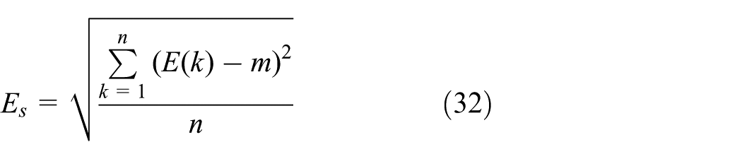
Tracking error standard deviation (TESD)
MATLAB software is utilized to simulate the developed XY gantry stage system. Based on the plant model obtained from system identification, simulation results are conducted and demonstrated for the gantry platform and optimized synchronous architecture, respectively. Three kinds of optimization methods, (a) PSO method, (b) conventional ABC method, and (c) the proposed CGABC method, are developed to learn the scaling factors
PSO method—the population size N is 30, and the leaning parameters are
Conventional ABC method—the colony size is set as 80, the employed bee number is 40, the onlooker number is 40, and the parameter Limit is set as 5. The upper bound
CGABC method—the colony size is set as 80, the employed bee number is 40, the onlooker number is 40, and the parameter Limit is set as 5. The upper bound
As shown in Figure 8(a), the reference star can be divided into five path segments of 50 mm side length. Figure 9(a)–(c) show the learning curves of the optimization process based on the
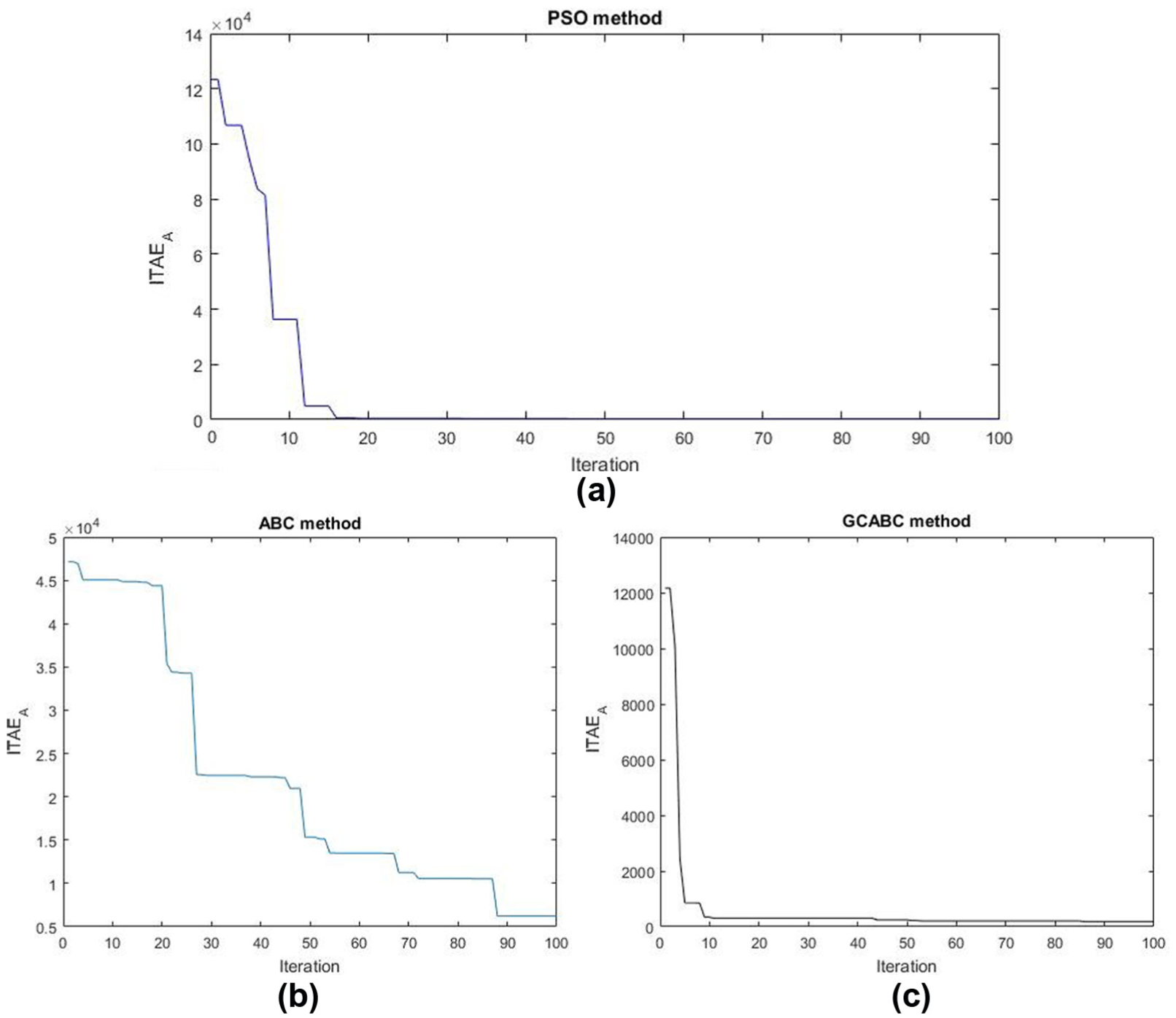
The learning curves of the optimization search in star trajectory using: (a) PSO method, (b) ABC method, and (c) CGABC method.
The optimal parameters of scaling factors for star trajectory.

ABC: artificial bee colony; PSO: particle swarm optimization; CGABC: cross-mixing global artificial bee colony algorithm.
The simulation results of star trajectory tracking error.

ABC: artificial bee colony; PSO: particle swarm optimization; CGABC: cross-mixing global artificial bee colony algorithm; ITAE: integral of the time-weighted absolute error.
Figure 8(b) illustrates the responses of circular outline with a diameter of 50 mm. It shows that the learning curves of the optimization process based on the

The learning curves of the optimization search in circle trajectory using: (a) PSO method, (b) ABC method, and (c) CGABC method.
The optimal parameters for circle trajectory.

ABC: artificial bee colony; PSO: particle swarm optimization; CGABC: cross-mixing global artificial bee colony algorithm.
The simulation results of circle trajectory tracking error.
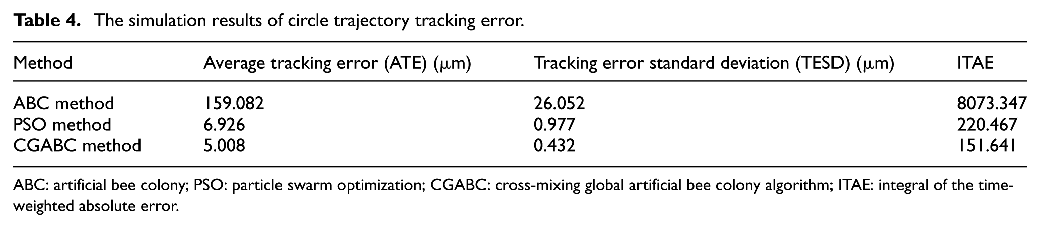
ABC: artificial bee colony; PSO: particle swarm optimization; CGABC: cross-mixing global artificial bee colony algorithm; ITAE: integral of the time-weighted absolute error.
Next, real-time control experiments are demonstrated to verify the results. Figure 11(a)–(d) show the X-axis position error, master Y-axis, slave Y-axis position errors, the synchronous error, and star trajectory, respectively. The results illustrate the smooth contour and smaller steady state errors for our gantry system. As can be seen, the synchronization error is always within 28 µm and can decrease gradually shown in Figure 11(c). Figure 12 shows the tracking error of the X-axis position, the associated master and slave Y-axis errors, synchronous error, and circular contour trajectory, respectively. The tracking errors in each axis can be substantially decreased, and our structure can accomplish better performance at steady state.

Experimental results of displacement response for the star contour tracking: (a) X-axis position tracking error, (b) master Y-axis and slave Y-axis position tracking errors, (c) the synchronous tracking error, and (d) star contour tracking trajectory.

Experimental results of displacement response for the circle contour tracking: (a) X-axis position tracking error, (b) master Y-axis and slave Y-axis position tracking errors, (c) the synchronous tracking error, and (d) circle contour tracking trajectory.
Table 5 lists the ATE and TESD tracking capabilities for star/circular reference contours. On average, the proposed fuzzy controller structure provides the 19.7965 µm in ATE, 27.864 µm in TESD, and 794.397 in
The experimental results trajectory tracking error.
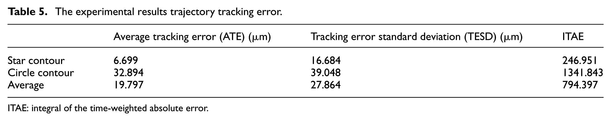
ITAE: integral of the time-weighted absolute error.
Conclusion
In this article, the fuzzy-based controller structure is proposed for precision trajectory tracking control in synchronized XY motion gantry stage system. An accurate identification process of PMLSM model with mechanical coupling effect has been investigated to verify the effectiveness of the developed architecture. The PID-type fuzzy architecture with simple structure and better approximation property is applied to improve the tracking performance of two-axis position system. The controller parameters are searched and optimized using CGABC algorithm to compensate the tracking error and synchronization error between the master and slave Y-axis motors. The CGABC algorithm with cross operation can take advantage of the information of global best solution and guide the search of new candidate solution to improve the property of exploration. Two motion trajectories are considered, that is, star and circular contours, to present the effectiveness of the developed system. The simulated and experimental results of star and circle reference contours are presented to show that the proposed CGABC-based fuzzy controller indeed accomplish the better tracking performances in terms of ATE and TESD indices. Our proposed method with fuzzy method is shown to be a feasible solution in practical implementation.
Footnotes
Handling Editor: James Barufaldi
Declaration of conflicting interests
The author(s) declared no potential conflicts of interest with respect to the research, authorship, and/or publication of this article.
Funding
The author(s) disclosed receipt of the following financial support for the research, authorship, and/or publication of this article: They would like to thank the Ministry of Science and Technology of the Republic of China, Taiwan, for financially supporting this research under contract no. MOST 105-2622-E-224-010–CC3, MOST 105-2622-E-224-017-CC3, and MOST 105-2218-E-150-004.