
Abstract
Temperature cracks commonly occur during mass concrete construction. Research shows that changes in temperature and peripheral constraints mainly cause crack formation in concrete. Engineers who lack experience often build structures prone to concrete cracks. Dams built in the high-altitude areas of Tibet are examples of such structure. Climatic conditions, such as large temperature variation and strong solar radiation, disrupt temperature control and crack prevention in concrete. In this study, we explored the measures for temperature control and crack prevention that are suitable for concrete structures, especially those built in high-altitude areas with large temperature variation and strong constraint zones. The study was performed in a steep slope dam section and stilling basin in Tibet. The finite element method was used to guide the engineering construction in the area. These methods could be applied to the construction of similar projects in other high-altitude areas.
Keywords
Foreword
Mass concrete has been extensively used in various infrastructure projects, such as water conservancy and hydropower projects, bridges, ports, and concrete dams. However, crack formation in these infrastructures remains to be a persistent problem.1–3 Since the 1930s, a set of theoretical systems for temperature control and crack prevention has been developed, along with several measures against crack formation in concrete; these measures include improving the crack resistance of concrete, blocking of concrete dams, pipe cooling, and preserving surface heat.4–7 However, no dam at home and abroad is free from crack, and such condition severely affects the durability and safety of structures. Engineering experience indicates that the difficulty in avoiding cracks is due to insufficient understanding of the mechanism of crack formation, the randomness of hydrometeorological conditions, and the failure of material parameters in reflecting actual engineering conditions; in addition, crack formation occurs because of the absence of timely and reasonable measures for temperature control that are tailored to the actual conditions of specific projects.8–13 Therefore, in the current condition in which a major breakthrough in the theory of temperature control is difficult to achieve,14–24 crack prevention should still be focused on the selection of timely and reasonable measures for temperature control.
The large-scale water resource development center in China has shifted their focus to high-altitude areas such as Sichuan and Tibet, where water resources are abundant and the development value is high but climatic conditions are complex, particularly featuring dry climate, large diurnal range of temperature, low average temperature, and strong solar radiation.25–27 These conditions render temperature control and crack prevention in projects difficult. As for the structures of steep slope dam sections and stilling basins, the strong constraints from the foundation are evident because of the special structural characteristics and location. Therefore, concrete construction in high-altitude areas faces great pressure in the prevention of crack formation. In the current work, we investigated the measures for temperature control and crack prevention, which are suitable for concrete construction in high-altitude areas with large temperature variation and strong constraint zones. The study was conducted in the context of a steep slope dam section and stilling basin in Tibet. The finite element method was utilized to guide engineering construction. The selected dam belongs to the steep slope section. By increasing the height of its simultaneous cooling zone (SCZ), controlling the water pipe cooling mode, and coordinating water flow time, the mutual constraints and shrinkage deformation of concrete can be reduced. Consequently, dam stress and cracking risk are minimized. Satisfactory results were obtained during dam construction. The proposed measures provide direction to the construction of similar projects in high-altitude areas.
Theory of numerical calculation
Finite element method of temperature field
At any point in the calculation field R, the unstable temperature field T (x, y, z, t) must satisfy the following continuous thermal conduction equation

where T is the temperature of concrete (°C), a is the temperature conduction factor (m2·h−1), θ is the adiabatic temperature rise (°C), τ is the age (day), and t is the time (day).
Using the variational principle as basis, the solution to the unstable temperature field differential control equation (1) under definite conditions is equivalent to the following functional extremum

The region R is discretized into a finite number of elements. At any point in each element, the temperature interpolation formula is

After substituting equation (3) into equation (2), the functional extreme conditions

where


Finite element method of stress field
Stress increments of concrete under a complex stress state include the elastic stress increment, creep stress increment, temperature and stress increment, dry shrinkage stress increment, and self-grown volume stress increment. Thus, we obtain

where
Concrete temperature strain increment

where
The concrete drying and shrinkage strain increment


where
At any time


By employing a physical equation, geometric equation, and equilibrium equation, we can obtain the finite element control equation at any time section

where
By using the above equations, we can obtain the displacement increment

We can obtain the displacement field and stress field at any time by accumulating the displacement increment and stress increment in each time section


Formation mechanism and contributing factors of mass concrete cracks
Formation mechanism of cracks
The causes of crack formation in concrete structures are complex. Material characteristics are the main internal factors of cracks, and the quality of construction, external environment temperature, and measures for temperature control are closely related to cracks.
Immediately after the pouring of concrete, the temperature of concrete rises due to the hydration reaction of cement. As a result of the effect of environmental temperature, the surface temperature of the structure is low, whereas the internal temperature is high. This condition results in variations of the internal and external temperature and temperature gradient. Interactive constraints subsequently occur in concrete. Therefore, a large temperature gradient equates to ease of crack formation. This phenomenon is particularly evident in high-altitude areas with large temperature variations. During the cooling stage, cracks easily form because the temperature drops. The shrinkage of concrete is subjected to the strong constraints from within the concrete, the upper and lower layers of concrete, and the foundation. Cracks generally form in the middle section inside a structure.
Research shows that when concrete temperature rapidly changes, the temperature difference is high, and the temperature drops sharply, the constraints that concrete is subjected are strong, and cracks easily form. Therefore, the measures for temperature control should be able to control the highest temperature, reduce the temperature difference, coordinate deformation, and reduce constraints, particularly for the structure of steep slope dams and stilling basins, which are subjected to strong constraints.
Measures for temperature control and crack prevention
Under the precondition that material characteristics, construction quality, and the factors of the external environment are increasingly difficult to control, improving the measures and standards for temperature control and crack prevention is essential. In high-altitude areas with dry climate, large diurnal range of temperature, low average temperature, and strong solar radiation, the measures for temperature control must be tested to ensure that they are timely and reasonable.
Surface heat preservation is an important measure for temperature control and crack prevention. The selection of insulation materials, insulation thickness, time to start heat preservation, and duration are all particularly important.
The principle of water pipe cooling is to furnish the cooling pipes inside the concrete to dissipate heat from hydration via the running cooling water.1,4,5 Pipe cooling can reduce the temperature difference between the internal and external sections of a structure and the temperature gradient, prevent surface crack formation at the early stage with an evident “reducing difference” effect, decrease the maximum temperature of the concrete, reduce the range of temperature drop, and prevent crack formation with a remarkable “cutting peak” effect. The double effect of “reducing difference” and “cutting peak” exceeds that of other measures, and the effect on crack prevention is apparent.
Further research shows that the objective to reduce mutual constraints and temperature stress can be realized through the unified management of all cooling pipes in a project, reasonable control of water cooling time and flow, coordination of cooling at various concrete layers, and further control of the cooling rate.
Numerical calculation model
Calculation model
A gravity dam is composed of multiple dam sections. This setup enables the dam to bear stress alone and maintain its balance by its own gravity. In this study, a steep slope dam section was selected as the research target. Considering a given range of foundations, we then established a three-dimensional (3D) structural model. Given that concrete is assumed to be a continuous homogeneous isotropic material, a 3D finite element method was adopted. The element was a hexahedral isoparametric element. Figure 1(a) presents a general calculation model that includes a dam section and a foundation. Figure 1(b) shows the dam zoning map of materials. The model was divided into 227,398 elements and 250,541 nodes.

Model and grid for calculation of no. 13 steep dam section: (a) general calculation model (b) dam material zoning.
The calculation model for the stilling basin is shown in Figure 2. Figure 2(a) illustrates the general model and pouring layers, including the stilling basin and fundament. Figure 2(b) is the model of the stilling basin itself.

Calculation model and grid of stilling basin: (a) general calculation model and pouring layers; (b) section of stilling basin grid.
Boundary conditions
During temperature field calculation, the upstream face of the dam is the third-class boundary before water storage and the first one after water storage; the downstream face is the third class. The result with sun radiation considered is shown in Figure 3(a).

Simulative calculation temperatures and stress boundary conditions of no. 13 steep dam section: (a) temperature boundary conditions and (b) stress boundary conditions.
During stress field calculation, the rock bottom is constrained in all three directions, and each side of the bedrock is constrained in a single direction; no constraint exists on top of the bedrock and dam (Figure 3(b)).
The boundary conditions for the temperature and stress calculation of the stilling basin model are the same as those of the dam (Figure 4).

Simulative temperature and stress boundary conditions of the stilling basin: (a) temperature boundary conditions and (b) stress boundary condition.
Positions of characteristic points
The amount of resultant data of the finite element method is huge, and the node for each moment generates its own calculation result. To further illustrate the problem, we selected the calculation results of several characteristic points for analysis. These results are expected to not only reflect the maximum stress value but also show the moment of the maximum value. This condition is reflected with the feature point process line. The feature points of the central section of the steep dam section and stilling basin are shown in Figure 5.

Typical points of central section: (a) steep dam section and (b) stilling basin.
Parameter model
The concrete of the dam body is four-graded concrete. (The gradation of concrete is divided according to the gradation of the aggregate. The aggregate of four-graded concrete features four particle sizes: 5–20, 20–40, 40–80, and 80–120 mm; the maximum particle size is 120 mm. Pumping concrete and non-mass concrete can only use one or two gradations. Concrete gravity dam and arch dam use four gradations.) Depending on the experimental data (Table 1), the formula of the adiabatic temperature rise of concrete is fitted in equation (19). Similarly, the fitting formula of elastic modulus is shown in equation (20) based on the experimental data (Table 2).


Experimental data on the adiabatic temperature rise of concrete.

Days of elasticity modulus test of concrete.

Self-grown volume deformation model
Directly inputting the experimental data (Table 3) of each age in the program and the deformation values between ages is achieved by spline function interpolation.
Days of self-grown volume test for concrete.

A negative value means that self-grown volume deformation is of shrinkage type.
Temperature-control measures during the construction of steep slope dam
This section presents the study on the temperature stress conditions of dam concrete under different temperature-control measures. Considering space limitations, we present three schemes on the basis of past engineering experience with special high-altitude climatic conditions. The difference between the former two schemes is the high level of SCZ, and the difference between two schemes is the pouring temperature. On the basis of this study, we obtain economical and reasonable measures for temperature control and crack prevention that are suitable to the selected area. The calculation scheme is shown in Table 4.
Operating mode sheet for no. 13 dam section.

(1) Concreting in summer; (2) to control the temperature at the end of first-phase cooling until the start of intermediate-phase cooling; when intermediate-phase cooling reaches the target temperature, temperature control begins until the end of second-phase cooling; (3) the temperature drop rate at the first phase is less than 0.5°C·d−1, and that at the intermediate phase is less than 0.3°C·d−1; (4) 12-13-14 represents the concreting temperatures at the strong constraint zone, weak constraint zone, and free zone, that is, 12°C, 13°C, and 14°C, respectively; the same is used hereafter.
Influence of the height of SCZ and cooling mode on temperature stress
This section presents the study on the influence of the height of the SCZ at the constraint zone of the foundation on the temperature of the dam concrete and stress. Operating modes 1 and 2 differ in terms of number and height of cooling zones (Table 4). Table 5 lists the results on the influence of the number and height of cooling zones on the temperature stress of the dam concrete. Figures 6 and 7 illustrate the temperature and stress process line at the characteristic points of different operating modes.
Influence of the number and height of SCZs on temperature stress.
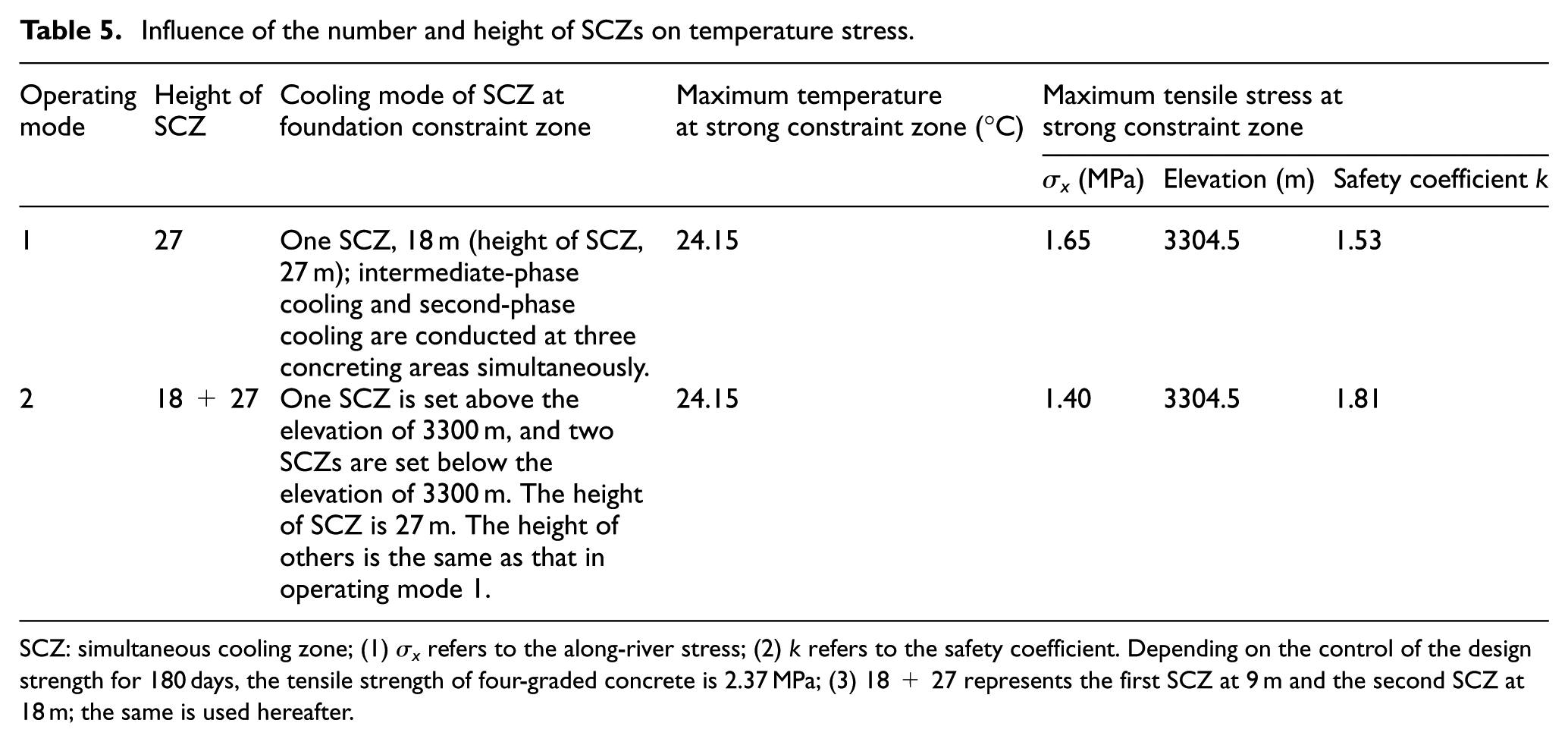
SCZ: simultaneous cooling zone; (1) σx refers to the along-river stress; (2) k refers to the safety coefficient. Depending on the control of the design strength for 180 days, the tensile strength of four-graded concrete is 2.37 MPa; (3) 18 + 27 represents the first SCZ at 9 m and the second SCZ at 18 m; the same is used hereafter.

Comparison chart of temperature process lines of different operating modes.
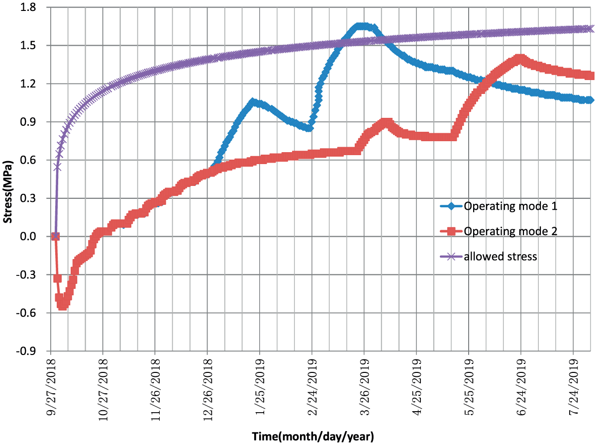
Comparison chart of along-river stress processes of different operating modes.
The diagrams demonstrate the following:
The height of the SCZ and the different cooling means have little effect on the maximum temperature. The highest temperature in the scheme for the SCZ is generally 24.15°C.
The height of the SCZ is 27 m, and the simultaneous cooling scheme begins at the intermediate-phase cooling. As a result of the small temperature difference and synchronous deformation between the upper and lower concreting areas, the constraint reaction on the concrete foundation is relatively small. However, given that the constraint zone of such dam foundation is steep and slopes with a 43 m axial height exist in the axial and along-river directions, the foundation constraint surface significantly increases. Furthermore, the foundation constraint reacting on the dam body is evident, and the along-river stress at the middle of the strong constraint zone is high with the maximum stress being 1.65 MPa, and the safety coefficient is 1.53.
Two SCZs are set above the elevation of 3300 m with a height of 27 m, which is basically within the slope range, starting from the intermediate-phase cooling. Changes in the height and cooling mode cause significant variations in the maximum stress at the middle of the strong constraint zone. As a result, the maximum stress falls to 1.40 MPa with a safety factor of 1.81, which increases evidently in comparison with that at operating mode 1.
The influence of the height and number of SCZs on concrete stress is evident, especially for steep dam sections such as the no. 13 dam section. SCZs can substantially affect concrete stress. The number and height of SCZs at this steep dam section should be increased as much as possible to wrap up the slope height and decrease the temperature stress. The result is the reduction in stress at the strong constraint zone and at the end of the second-phase cooling.
Influence of concreting temperature on temperature stress
In this section, the influence of different concreting temperatures on the temperature stress of the dam body is studied. Table 6 shows the results of the temperature stress of the dam body concrete at different concreting temperatures. Figures 8 and 9 illustrate the temperature and stress process line at the characteristic points of different operating modes, respectively:
When the concrete lift thickness at the strong constraint zone is 1.5 m, the temperature of the concrete poured during summer and the concreting temperature are 12°C and 14°C, respectively. Whenever the concreting temperature rises by 2°C, the maximum temperature of the dam concrete increases by approximately 0.8°C, the maximum stress increases from 1.40 to 1.45 MPa at 0.05 MPa increments, and the safety coefficient of crack resistance decreases from 1.81 to 1.74.
When the concrete lift thickness at the weak constraint zone and free zone is 3.0 m and the concreting temperature increases by 2°C, the maximum temperature of the dam concrete increases by approximately 1.48°C, and the maximum stress at the free zone increases by about 0.02 MPa. This change is due to the cooling pipe interval becoming 1.5 × 3.0.
Under the same conditions of the temperature-control measures, the increase in the maximum temperature caused by the increase in concreting temperature causes increases in the maximum temperature of the concrete, temperature difference at the foundation, and maximum tensile stress. Reducing the concreting temperature can result in improved temperature control.
Influence of different concreting temperatures on temperature stress.

12-13-14 refers to the concreting temperatures at the strong constraint zone, weak constraint zone, and free zone, respectively.

Comparison chart of temperature process lines of different operating modes.

Comparison chart of along-river stress processes of different operating modes.
Temperature control and crack prevention for stilling basin
Basic operating mode
The height of the stilling basin is relatively small. The entire structure falls within the scope of the strong constraint area of the bedrock. The requirements for temperature control and crack prevention measures are stringent. In this section, we present three schemes for temperature stress analysis. We establish Scheme 1 depending on engineering experience. On the basis of this scheme, the approach to water cooling is adjusted to achieve economical and optimal temperature control and crack prevention. The calculation schemes of the stilling basin are shown in Table 7.
Operating mode calculation sheet for stilling basin.

(1) Concreting at high temperature during summer; (2) the intermediate-cooling operating mode, which begins at the end of the first-phase cooling; (3) the temperature drop rate of the first-phase cooling is less than 0.5°C·d−1. The temperature drop rate of the intermediate-phase cooling is less than 0.3°C·d−1; (4) the structure of the stilling basin is located within the strong constraint zone.
Absence of water cooling
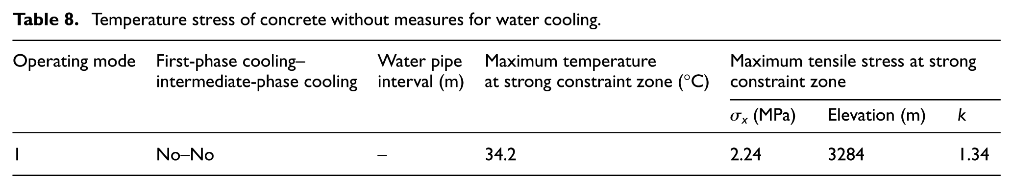
Table 7 shows the specific schemes for exploring the distribution law of concrete temperature and stress without water cooling. Table 8 presents the results of temperature stress. Figures 10 and 11 present the temperature and along-river stress process lines of concrete, respectively.
Temperature stress of concrete without measures for water cooling.

Temperature process line of concrete.

Along-river stress process line of concrete.
The diagrams indicate the following:
When no water cooling measures are available, the maximum temperature of the concrete reaches 34.2°C and the maximum stress is 2.24 MPa. These conditions occur when the concrete temperature decreases to the stable temperature. The safety coefficient is only 1.34.
The stilling basin concrete is a mass concrete structure because of its large thickness (>8 m). By contrast, the stilling basin structure is located at the strong constraint zone, and the stress caused by the shrinkage resulting from the temperature drop is large. Therefore, the measures for water cooling should be considered to reduce the temperature and its variation at the foundation.
Setup of first-phase cooling
Given that no measure for temperature control is available, the maximum temperature inside the concrete, the temperature difference at the foundation, and the concrete shrinkage stress carry large values, whereas the safety coefficient has a low value. The addition of first-phase cooling measures for temperature control is studied in this section to cut the peak of the concrete temperature and reduce stress.
Table 9 presents the results of the temperature of the dam body without first-phase cooling. Figures 12 and 13 show the temperature and along-river stress process lines under different operating modes.
Influence of first-phase cooling measures on the temperature stress of concrete.


Comparison of the temperature process lines of different operating modes.

Comparison of along-river stress process lines of different operating modes.
The diagrams indicate the following:
When the first-phase cooling is added, the maximum temperature decreases from 34.2°C to 27.1°C. With a temperature difference of 4.1°C, the maximum along-river stress decreases from 2.24 to 1.54 MPa, and the safety coefficient increases from 1.34 to 1.95. The first-phase cooling can effectively cut the temperature peak, reduce the temperature difference at the foundation, and reduce the maximum tensile stress.
Setup of intermediate-phase cooling
Given that concrete temperature rebound is high when first-phase cooling is set up, intermediate-phase cooling is planned to be set up in such a way that its effect on temperature and stress can be easily studied. Table 10 presents the comparison of the effects of the presence and absence of intermediate-phase cooling on temperature and stress. Figures 14 and 15 illustrate the comparison of temperature and stress process lines, respectively.
Influence of first-phase cooling measures on concrete stress.


Comparison of temperature process lines of different operating modes.

Comparison of stress process lines of different operating modes.
The diagrams indicate the following:
When intermediate-phase cooling is added, the stress at the later stage declines. When no intermediate-phase cooling is added, the maximum stress at the strong constraint zone is 1.54 MPa, and the safety coefficient is 1.95. When intermediate-phase cooling is added, the maximum stress at the strong constraint zone decreases to 1.38 MPa, while the safety coefficient increases to 2.17. Although the stress at the early stage increases to a certain extent, it remains within the allowed limit with a high safety coefficient.
In terms of the concrete of the stilling basin, the optimal temperature-control effect can be achieved by reducing the maximum temperature, the temperature difference at the foundation, and cooling as early as possible.
Conclusion
The climatic conditions in high-altitude areas in Tibet are complex. In particular, these areas experience dry climate, large diurnal range of temperature, low average temperature, and strong solar radiation. These characteristics make temperature control and crack prevention for mass concrete difficult to achieve. Given that the construction of steep slope dams and stilling basins in such areas is subjected to foundation constraints, crack prevention is a serious challenge.
For the reduction of stress in concrete at a strong constraint zone, the height of the SCZ should be increased as much as possible to coordinate the temperature difference and deformation between the concrete lifts and reduce the temperature stress. One SCZ at the height of 27 m should be set up at the foundation constraint zone above the elevation of 3300 m along with simultaneous cooling at the beginning of the intermediate-phase cooling. Reducing the concreting temperature can achieve optimal temperature control.
Stilling basin concrete is a mass concrete because its thickness is >8 m. It is subjected to strong foundation constraints. If no measure for temperature control is available, the stress becomes large and may cause large cracks. When first-phase cooling is performed, the temperature peak is likely to be cut, the temperature difference at the foundation decreases, and the maximum tensile stress decreases significantly. When intermediate-phase cooling is added, the stress at the later stage can be reduced, and the safety coefficient can be significantly increased for a large safety margin.
Footnotes
Handling Editor: Farzad Ebrahimi
Declaration of conflicting interests
The author(s) declared no potential conflicts of interest with respect to the research, authorship, and/or publication of this article.
Funding
The author(s) disclosed receipt of the following financial support for the research, authorship, and/or publication of this article: This study was supported by the National Natural Science Foundation of China (grant nos. 51579252, 51578544, and 51439005), the National Basic Research Program of China (973 Program 2013CB036406 and 2013CB032904), the 35th Science and Technology Support Project (2016YFC0401608), IWHR, and the Basin Water Cycle Simulation and Regulation of State Key Laboratory Special Research Foundation.