
Abstract
In this article, a new type of magnetorheological brake is designed and its torque characteristics are investigated experimentally. The proposed magnetorheological brake consists of an outer housing, a rotating drum, magnetorheological fluid, and a copper wire coiled magnetic core to generate a magnetic field. At first, the structural configurations of the magnetorheological brakes are presented with conventional and modified magnetic core shape. To achieve enhanced braking torque under limited small size, a modified magnetic core shape is adopted in the proposed magnetorheological brake. After manufacturing the magnetorheological brakes and measurement of braking torque, it is verified that the proposed magnetorheological brake with modified magnetic core shape has improved braking torque compared to conventional-type magnetorheological brake. For the actuator application, the dynamic characteristics, such as rising time, settling time, and falling time, of the proposed magnetorheological brake is also experimentally evaluated by observing the step response. In addition, the torque tracking control performance is also investigated by adopting fuzzy–proportional–integral–derivative control algorithm for desired input of sinusoidal and multi-magnitude step input. It is demonstrated that the proposed magnetorheological brake can be successfully used as an actuator with limited small size.
Keywords
Introduction
Magnetorheological (MR) fluid is a kind of smart material, and its rheological property is changeable in response to an external magnetic field because MR fluid is composed of ferromagnetic particles and carrier fluid such as mineral, hydrocarbon, and silicone oil. By applying magnetic field, the particles combine to form chain structures aligned with the magnetic flux lines. These chain structures interfere with the fluid flow, and shear stress of MR fluid can be obtained. The change in rheological property of MR fluid is reversible and the response time is very small in milliseconds. The magnitude of shear yield stress is related to the bond strength of the chain structure and can be continuously controlled by the magnitude of the external applied magnetic field. MR fluid has great potential for many mechanical engineering fields that require an electromechanical interface. Among many applications, MR damper for suspension system of ground vehicle is a most widely investigated device. 1 Other types of MR devices for vehicle applications also have attracted much attention such as seat damper, engine mount, clutch and brakes.2–5
Among the mechanical MR devices, MR brake is one of the widely studied devices that have capability of reducing and stopping the rotational speed of a shaft using MR effect. Many research works have been carried out for the design and control of MR brake. Design and model of MR brakes has been reviewed by Imaduddin et al. 6 In the review, MR brake was classified into three types according to its structural design, drum type, disc type, and hybrid type. The characteristics of each type of MR brake were identified and mathematical modeling techniques were reviewed in detail. Most studies have focused on achievement of high-torque output with a compact structure. Then, many research works have been conducted for design parameter optimization and proposal of a new structural configuration. Nguyen and Choi 7 reported the optimal design of different types of MR brake constrained in a specific volume. Suleman’s group proposed an optimal design for two-disc MR brake for vehicle application, and wheel slip control performance was evaluated by adopting sliding mode control algorithm. 8 They also studied about circuit optimization and material selection for the MR brake components. 9 Sohn et al. 10 carried out design parameter optimization of MR brake for a mid-sized motorcycle, and the mechanical characteristics, such as response time, braking torque, and temperature variation, were evaluated via experiment. Wu et al. 11 proposed a new MR brake with multi-pole and dual-gap configuration to increase the range of controllable transmission torque as well as the output torque while maintaining a compact structure.
In recent days, many research works have been reported for the MR brake with a haptic actuator application. Liu et al. 12 studied the design, modeling and experimental performance evaluation of MR brake, and the applicability to the haptic actuator was verified. Li et al. 13 proposed a new MR fluid-based two degree-of-freedom (2-DOF) haptic joystick and applied to virtual reality demonstration with typical 2D and 3D interface examples. Senkal and Gurocak 14 proposed a design of an MR spherical brake as a multi-DOF actuator for haptic application, and experimental identification was conducted for virtual wall collision, damping, and Coulomb friction simulations. Nguyen and Choi 15 proposed an optimal design of bi-directional MR brake for medical haptic system, and its performance was validated via experiment. The proposed bi-directional MR brake can transmit generated active and semi-active braking torque. Song et al. 16 proposed a new design of 4-DOF haptic master device using MR clutches for the application to a robot-assisted minimally invasive surgery system. The proposed master consists of two actuators: an MR bi-directional clutch associated with a planetary gear system and an MR clutch with a bevel gear system. However, in haptic actuator application, most research works for MR brake have focused on the performance improvements of high braking torque. In this case, in order to obtain sufficient performance as desired, the size of the brake becomes large. Especially, in such a case, it is difficult to apply to real systems because compact size and simple structure are also important issues for successful applications for practical application systems.
The main technical contribution of this work is to propose a new type of MR brake whose structure is simple and compact, but braking control performance is excellent. A new type of MR brake which increases the area where the MR effect is generated by modifying the shape of the magnetic core is designed and it is demonstrated through experiments that the proposed MR brake has better performance than the conventional MR brake. As a first step to achieve this goal, a structural configuration of the proposed MR brake is presented and basic operating concept of the proposed MR brake is explained in detail. After manufacturing both conventional and the proposed MR brakes, braking torques are measured according to input current and compared to each other. To identify the actuator performance, dynamic characteristics of the proposed MR brake is identified by observing time step response. In addition, torque tracking control performance for desired torque profile is evaluated by adopting fuzzy-proportional–integral–derivative (PID) control algorithm. It is demonstrated that the proposed MR brake can provide enhanced braking performance and can be successfully applied to the haptic actuator under limited small size.
System model
According to its structural configuration, MR brakes can be classified into two types, disc-type and drum-type brake. For a disc-type MR brake, the rotor is thin and the braking torque is mainly generated between the MR fluid and top/bottom surface of the disc. For a drum-type MR brake, the rotor is thicker and the torque is generated between the MR fluid and the outer radius of the rotor. The controllable torque generated from MR effect can be expressed as following two equations for disc-type and drum-type MR brake, respectively


where

Structural configuration of the MR brake.
The total braking torque of the proposed MR brake can be expressed as follows

here,


where
In this work, to satisfy the design constraint of small-sized MR brake, a drum type is selected and to achieve high braking torque, modified magnetic core shape is proposed. The basic design concept of the proposed modified magnetic core shape can be explained based on Figure 2. The conventional magnetic core shape and the proposed modified magnetic core shape are shown in Figure 2(a) and (b), respectively. In the sectional view of MR brake, the conventional and the modified magnetic core has square and trapezoidal cross section, respectively. By adopting the modified magnetic core shape, the path of magnetic flux is enlarged and the length of area (presented in blue color in Figure 2) where the occurred MR effect is increased as shown in Figure 2(b). Of course, the shear stress can be reduced to a certain degree because the magnetic flux density B generated in the MR fluid region may be decreased. If the increment of the length d of region where MR effect occurs is greater than the decrement of shear stress, the variable

Schematic diagram of magnetic circuit: (a) conventional type and (b) proposed type.
The geometric dimensions of the conventional and the proposed MR brake are presented in Figure 3(a) and (b), respectively. The outer radius and height of MR brake are determined as 35 and 54 mm, respectively. Under the consideration of grasping by human hand in the applications, the diameter of MR brake is determined as 70 mm, and it is a little bit bigger than that of beverage can. The radius of rotating drum is 20 mm, and the gap between rotor and magnetic core is 1 mm. The height of magnetic core is 24 mm and the width of magnetic core is 7 mm. As shown in Figure 3(b), the proposed magnetic core has trapezoidal cross section.

Geometry of the MR brakes: (a) conventional type and (b) proposed type.
Results and discussions
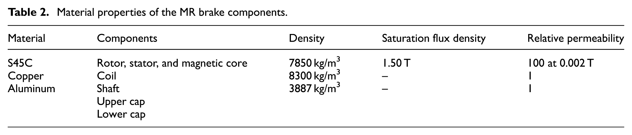
The manufactured MR brakes are presented in Figure 4(a)–(c) for components of conventional type, components of the proposed type, and assembly, respectively. As shown in Figure 4(a) and (b), the shape of magnetic core is different and other components are the same. A rotating drum made of magnetic steel is fastened to a shaft made of aluminum. A bobbin-less magnetic core made of magnetic steel is fixed housing and upper and lower end capes. To reduce the total volume of MR brake, bobbin-less-type magnetic core was adopted in this work. A copper wire is directly wound around the magnetic core. It was shown that there is no performance change for with and without bobbin in magnetic core. 17 The diameter of copper wire is 0.5 mm and the number of turns is 320. The space between the drum and the magnetic core is filled with MR fluid. MR fluid of model MRF-132DG of Lord Corporation is used in this work. The material properties of MR fluid and components of MR brake are listed in Tables 1 and 2, respectively. To evaluate the performance of the MR brakes, experimental setup is prepared as shown in Figure 5. A direct current (DC) motor is used to generate driving torque to rotate the shaft and connected to the shaft of the manufactured MR brake. Between the driving motor and MR brake, a torque transducer is installed to measure the generated torque from the MR brake. By applying electric current to coils, a magnetic field is produced in the MR brake, increasing yield stress of the fluid. Thus, the rotating drum is forced to slow down or brake according to the magnitude of the applied current. Both the measured braking torques according to applied electric currents for conventional and the proposed MR brake is presented in Figure 6. It is definitely observed that the proposed-type MR brake can generate about 10% larger braking torque compared with conventional-type MR brake for each applied current from 0.5 to 2.0 A. About 4.1 N m of braking torque is generated from the proposed MR brake at 2.0 A of input current. It is clearly verified that the proposed-type MR brake can generate enhanced braking torque compared to conventional-type MR brake. It is also observed that the zero-state braking torque, without applying current, is about 0.3 N m, and it is caused from the torques by viscosity of MR fluid and mechanical frictions. It is noted that human cannot feel any resistance to rotate the shaft by human hand against to 0.3 Nm of braking torque.
Rheological properties of MR fluid (132-DG).

Material properties of the MR brake components.

Manufactured MR brakes: (a) components of the conventional type, (b) components of the proposed type, and (c) photograph of assembly.

Experimental setup.

Measured braking torques according to input current.
To investigate dynamic characteristics of the proposed MR brake, step response of the MR brake is measured and the result is presented in Figure 7. After 5 s, 0.5 A of current is applied to the MR brake for 10 s and then removed. The 63% rising time, 2% settling time, and falling time is 60, 350, and 150 ms, respectively. The steady state error is measured as 0.026 N m.

Measured step response of the MR brake.
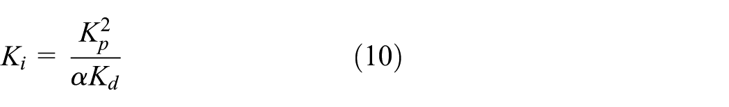
To evaluate the torque tracking control performance of the proposed MR brake, fuzzy-PID control algorithm is designed and implemented to the system. The control gains of PID controller are determined based on the fuzzy algorithm. Control input of discrete-time PID controller,


where

here,


The torque tracking control performances are evaluated experimentally for the desired inputs such as sinusoidal input and multi-magnitude square input, and the results are presented in Figure 8. As shown in Figure 8(a), the desired torque profile is designed as 1 Hz of sinusoidal signal and the magnitude is set from 0.5 to 2.5 N m to remove the effect of zero-state torque. It is observed that the generated braking torque with red solid line is well matched to the desired braking torque with black dashed line. For the square input with multi-magnitude desired input, the generated braking torque is tracking the desired input perfectly, as shown in Figure 8(b). The control input currents for torque tracking control in Figure 8(a) and (b) are also presented in Figure 9(a) and (b), respectively. From those results, it is verified that the proposed MR brake has good torque tracking control performance and can be successfully applied to medical haptic actuator.

Tracking control performance: (a) sinusoidal input of 1 Hz and (b) square input with multi-magnitude.

Control input currents: (a) sinusoidal input of 1 Hz and (b) square input with multi-magnitude.
Conclusion
In this work, a new type of MR brake has been designed for a haptic actuator application, and its performances have been evaluated experimentally. For the proposed MR brake, the shape of magnetic core was modified to achieve high braking torque compared with the conventional MR brake. After manufacturing both the conventional and the proposed MR brakes, actuating torque was measured and it was observed that more than 10% of larger torque was obtained for the proposed MR brake. To evaluate the dynamic characteristics of the proposed MR brake, step response was observed and the transient specifications such as rise time, settling time, overshoot, and falling time were identified. For example, the rise time and settling time of the proposed MR brake were identified by 60 and 350 ms, respectively. In addition, by adopting the fuzzy-PID control algorithm, torque tracking control performances were evaluated for the sinusoidal and square desired trajectories. The suitability of the proposed MR brake to application of a haptic actuator was clearly demonstrated by the results. Since the braking performance depends on MR fluid type, the evaluation of braking performance according to MR fluid type will be also carried out in the next step of this study. It is finally noted that after undertaking parameter optimization, the proposed MR brake will be installed to a haptic master device for the teleoperation and the field tests will be undertaken as a second phase of this work.
Footnotes
Handling Editor: Filippo Berto
Declaration of conflicting interests
The author(s) declared no potential conflicts of interest with respect to the research, authorship, and/or publication of this article.
Funding
The author(s) disclosed receipt of the following financial support for the research, authorship, and/or publication of this article: This paper was supported by Research Fund from Kumoh National Institute of Technology.