
Abstract
To enhance the braking torque, this study proposes a multi-arc cylindrical magnetorheological fluid brake. Firstly, the structure and operational principle of the multi-arc cylindrical magnetorheological fluid brake is described in detail. Through finite element magnetic field analysis, the influence of arc radius variations and excitation current levels on flux density distribution are investigated. It is found that a larger arc radius in the multi-arc working gap leads to a lower average magnetic field strength. Then, a theoretical model is subsequently established to calculate braking torque within the working gap of a multi-arc magnetorheological fluid brake. The comparative evaluation of braking torque between the multi-arc configuration and conventional cylindrical counterparts demonstrate more than 42.20% torque enhancement under equivalent magnetic flux density conditions. To validate the theoretical predictions, a dedicated test platform was developed, with experimental measurements showing less than 5% deviation from theoretical data at magnetic saturation. These findings establish fundamental guidelines for optimizing magnetorheological brake geometries and provide actionable insights for industrial applications requiring high-torque compact braking solutions.
Introduction
As a novel smart material, magnetorheological fluid (MRF) exhibits unique rheological properties in response to an applied magnetic field. 1 MRF are composed of micrometer-sized magnetizable particles dispersed in appropriate carrier liquids. In the absence of a magnetic field, MRF exhibits as a Newtonian fluid. However, when subjected to an external magnetic field, its structure and properties undergo remarkable transformations. 2 The particles acquire large magnetic moments aligned with the magnetic field direction, giving rise to strong magnetic interactions. This subsequently leads to the formation of complex particle aggregation networks. 3 The MRF rapidly transforms from a Newtonian fluid into a solid-like material within milliseconds, under an applied magnetic field. 4 This causes MRF to lose fluid mobility and exhibit Bingham plastic behavior characterized by a specific shear yield stress. 5 As the strength of the applied magnetic field increases, the yield stress of MRF also increases. The yield stress of MRF can be continuously adjusted by the intensity of the applied magnetic field. 6 Due to these mechanical properties, MRF has broad application prospects in automotive, construction, machinery, aviation, medical, and other fields. 7 There are series of MRF devices have been developed, including MRF brakes, 8 clutches, 9 couplers, 10 shock absorbers, 11 dampers, 12 polishing machines, 13 valves, 14 and other related devices. 15
Based on the reversible and rapid response characteristics of the magnetorheological effect, researchers have successfully applied MRF in the domain of brake device. 16 For example, Wu et al. 17 introduced the main structure and operational principle of MR brakes and clutches, based on the operational modes of MRF. It also provides a summary of the structural configurations of MR brakes and clutches, developed over the past 15 years. Huang et al. 18 investigated the design method of a cylindrical MRF brake and derived the corresponding torque equation. Kikuchi and Kobayashi 19 designed a cylindrical magnetorheological fluid brake with a maximum torque of 10 N m. The braking torque was compared with the estimated torque using finite element software, a magnetostatic analysis was carried out, and a mathematical model of the magnetorheological fluid was proposed. Wang et al. 20 developed a new MRF brake with capable of generating high torque and used water cooling to facilitate heat dissipation. In order to promote the application of MRF devices, scholars are committed to improving their transmission torque. Wu et al. 21 substituted a single-disk MRF device by a multi-disk one and demonstrated that the maximum output torque of the multi-disk device could achieve 1880 N m. Qin et al. 22 substituted a single-cylinder MRF device by a stacked-cylinder one, with the capability to attain a maximum torque of 403 N m. However, changing from a single-disk to a multi-disk configuration and from a single-cylinder to a stacked-cylinder design leads to considerable heat production within the device. This heightened thermal output will deteriorates the transmission performance of the MRF, ultimately affecting the overall efficiency of the MRF device as temperatures rise. 23 It has been found that the shape of the MRF working gap also has an impact on the transmission performance of the MRF device. Sun et al. 24 developed a novel high-torque arcuate multi-disk MRF coupling structure and formulated a corresponding mechanical torque transmission model. Pilon et al. 25 designed a MRF clutch with a helical fluid flow path, enhancing its durability by 42%. Sun et al. 26 introduced a pendulum corrugated MRF coupling based on the MRF shear-pressure mixing mode. This design optimizes the formation of magnetic chains through a curved magnetic guiding surface, thereby improving the device’s dynamic torque transmission capability.
To enhance the braking performance of MRF brakes, this study presents an innovative multi-arc MRF braking system. The proposed design incorporates a multi-arc shape for the MRF working gap, significantly expanding the effective working interface. Through finite element analysis, the magnetic field characteristics were investigated under three key parameters: (1) arc radius variation within fixed device dimensions, (2) comparative analysis between arc-shaped and conventional cylindrical configurations, and (3) current intensity effects on magnetic field generation. The relationship between braking torque with arc curvature, magnetic field intensity, and the speed of the driving shaft was established. The theoretical results were analyzed for multi-arc configurations, with quantitative comparisons against traditional cylindrical designs. Ultimately, experimental verification is performed. This investigation not only demonstrates the performance advantages of arc-optimized MRF brakes but also provides a design methodology for next-generation smart braking systems.
Work principle
Figure 1 presents the structure of the multi-arc cylindrical MRF brake. The device primarily consists of a driving shaft, excitation coils, a stationary cylinder, bearing end caps, and specially designed working gap. The arc-shaped cylindrical working gap between the driving and stationary cylinder is filled with MRF and configured as multiple arc-shaped channels to enhance magnetic field utilization.

Two-dimensional structural diagram of the multi-arc cylindrical MRF brake.
The operational principle of the device unfolds in three distinct stages. In the initial standby state, there is no magnetic field generated in the excitation coil, the minimal viscous torque produced by the MRF is insufficient to effectively braking the driving shaft. When the excitation coil is energized, a perpendicular magnetic field permeates the multi-arc MRF working gap. Consequently, the magnetic particles within the MRF align along the magnetic field lines, forming chain-like structures that generate shear stress. This shear stress, in turn, produces a braking torque. During brake disengagement, the current supply to the coil is cut off, the magnetic field dissipates instantaneously, causing the MRF to revert to its Newtonian fluid state and resulting in the complete cessation of braking torque. Notably, the braking torque can be accurately controlled by adjusting the input current to the excitation coil.
Finite element analysis of magnetic field
To maximize the braking torque output of the MRF brake, the working gap of the MRF is designed in a multi-arc cylindrical shape consisting of multiple arcuate surfaces. A two-dimensional axisymmetric steady-state magnetic field analysis was implemented through finite element modeling to evaluate the structural design efficacy of this multi-arc geometry. Figure 2 and Table 1 illustrate the simplified finite element analysis model and the detailed dimensions of the MRF brake device, respectively.

Finite element analysis model of MRF brake.
Structural parameters (mm).

To verify the braking performance of the multi-arc cylindrical MRF brake proposed in this study, the shape of the MRF working gap was modified while keeping all other structural dimensions identical to those of the traditional MRF brake. Huang et al. 18 proposed that an effective working gap thickness h = 1 mm for MRF maximizes the utilization of its rheological properties. To ensure consistent structural dimensions and overall design rationality between the multi-arc cylindrical MRF brake and the traditional counterpart, the radii of the individual arcs were set to 1, 2, and 3 mm, respectively.
The driving shaft and the driven part are made of Steel-1010 and Steel-1030, respectively. Meanwhile, the coil and isolation ring are made of copper. The MRF-J01T is specifically selected for its field-responsive properties. The manufacturer of MRF-J01T is Chongqing Materials Research Institute. The material properties of MRF-J01T as shown in the Table 2.
Material parameters of MRF-J01T.

The shear yield stress curve of MRF-J01T approximated through polynomial fitting. 27

Where,
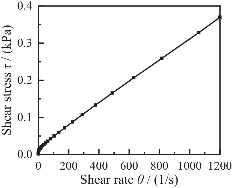
The shear stress-shear rate curve of MRF-J01T.
Effect of arc radius on the magnetic field
To investigate the impact of arc radius on the magnetic field, the arc radii are setted to 1, 2, and 3 mm respectively, meanwhile maintaining a constant 1 mm thickness for the MRF working gap. Figure 4 illustrates the magnetic flux density distribution within the localized MRF working region under a 3.0 A excitation current.

Magnetic field contour plots of the MRF working gap with different arc radii: (a) cylinder shape, (b)
Figure 4 shows that the magnetic field distribution within the multi-arc working gap is more inhomogeneity compared to that in the cylindrical working gap. The arc structure creates a sharp point at the juncture of two arcs, resulting in significant variations in magnetoresistance around this point. As a result, the magnetic flux density at this location differs from that in its surroundings, leading to an uneven magnetic field distribution. By comparing the magnetic field distributions in (b) to (d) of Figure 4, it can be observed that the radius of the arc has a significant influence on the uniformity of the magnetic field distribution. It can be found that the larger of the arc radius, the more influence of the sharp part of the arc transition on the magnetic field distribution of the working gap. Moreover, the magnetic field lines in the MRF working area of the upper and lower surfaces are deflected, which is due to the difference in relative permeability of the material surfaces on both sides. Figure 5 shows the average magnetic field intensity for each arc transmitted from left to right, and Table 3 presents the range of magnetic field intensity variation across the MRF working gap area.

Variation in average magnetic field intensity within a single arc: (a)
Variation in magnetic field intensity within multi-arc shape working gap (I = 3 A).

As shown in Figure 5, the average magnetic field intensity exhibits a consistent trend across different arc radii. The intensity distribution within each arc area is largely symmetrical along the geometric axis, with peak values occurring in the working gap adjacent to the excitation coil.
Table 3 indicates that when the arc radius r = 1.0 mm, and the average magnetic field intensity in the working gap is higher. Given that magnetic particle chain formation in MRF depends on magnetic field intensity, increased magnetic field intensity can enhance braking performance. 28 Based on these findings, the arc radius is selected as r = 1.0 mm.
Effect of current on magnetic field
In addition to analyzing the impact of arc radius on the magnetic field, this study will also investigates the influence of coil current (I) on the magnetic field. The coil current is continuously varied from 0 to 3.5 A. Figure 6(a) and (b) respectively show the magnetic field distribution for the multi-arc shape and cylindrical shape at I = 3.0 A. It is clear from Figure 6 that when the current is relatively high, magnetic saturation occurs in the MRF working gap. Therefore, I = 3.0 A is selected for finite element analysis of the magnetic field in MRF brake as shown in Figure 6. The magnetic flux density along the axial direction is higher at both ends and lower in the middle. For an axial working gap length of 100 mm, the effective working gap lengths for the multi-arc and cylinder are 157 and 100 mm, respectively. The average magnetic field intensities in these regions at different currents are shown in Figure 7(a) and (b).
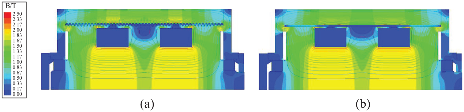
Magnetic field contour plots of the MRF working gap with different shape (I = 3.0 A): (a) multi-arc shape and (b) cylinder shape.

Variation in magnetic field intensity of MRF working gap with different shape: (a) multi-arc shape and (b) cylinder shape.
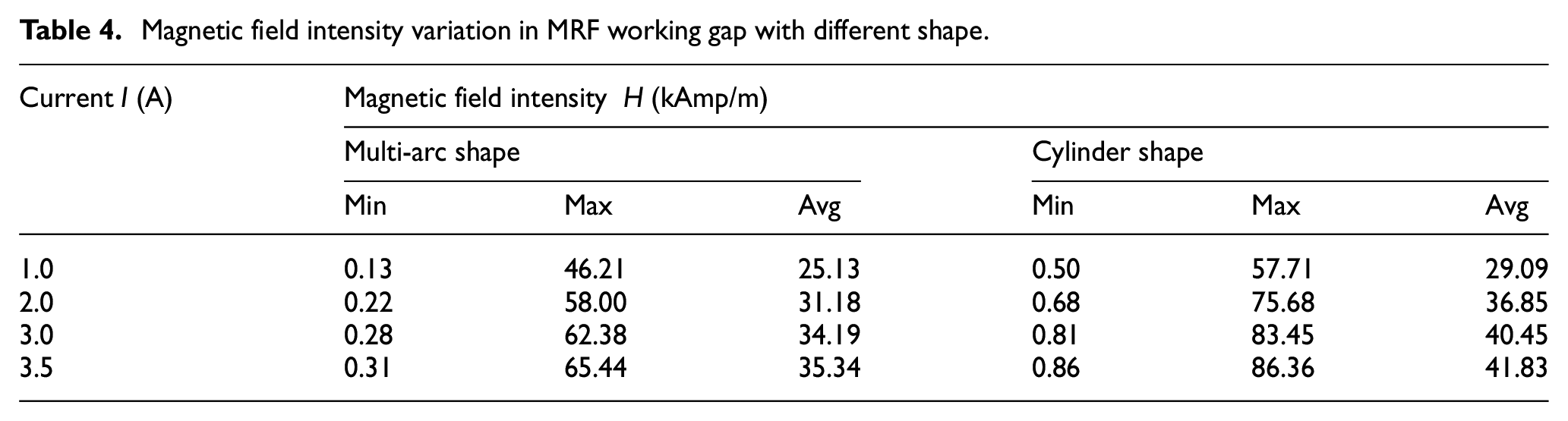
Figure 7 indicates that due to the symmetrical arrangement of coils within the MRF brake, the magnetic field generated by the coils decreases with increasing distance from the coils. The lowest intensity is at the spacer ring, and the highest is at the contact point between the magnetic material and the driving cylinder. Table 4 presents the magnetic field intensity (H) in the working gap. According to Table 4, the magnetic field intensity in the MRF working gap gradually increases with the increase in current, but the increase rate decreases over current. Specifically, when the current is increased from 1 to 2 A, from 2.0 to 3.0 A, and from 3.0 to 3.5 A, the increase rates of average magnetic field strength in the multi-arc shape working gap are 24.07%, 9.65%, and 3.36%, respectively. Additionally, the traditional cylindrical shaped working gap exhibits increase rates of 26.68%, 9.77%, and 3.41%, respectively. Although the average value and increase rate of magnetic field strength in the multi-arc shape working gap are lower than those in the traditional cylindrical shaped working gap, the effective length of multi-arc shape working gap is 57% longer than that of traditional cylindrical shaped working gap.
Magnetic field intensity variation in MRF working gap with different shape.
Theoretical model of MRF braking torque
To derive the theoretical model of braking torque for a multi-arc MRF brake, the MR torque within a single semicircular gap was analyzed in cylindrical coordinates (ρ, θ, z), as illustrated in Figure 8.

Illustration of the single semicircular working gap.
The Bingham model is used to characterize the rheological properties of MRF, with the constitutive relationship formulated as follows 29 :

Where,
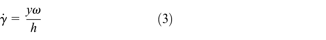
Where,

Where,

Where,

The braking torque generated by the MRF in an infinitesimal arc (

Integrating equation (7) allows us to obtain an expression for the braking torque

The total braking torque, denoted as
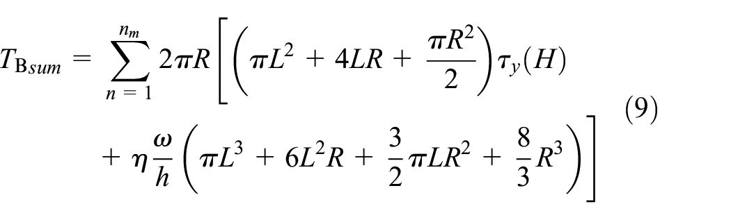
Where,
To analyze the multi-arc MRF braking system, its structural and operational parameters are defined. The multi-arc MRF braking system has a radial length L = 40 mm, a working gap thickness h = 1 mm, a viscosity of MRF η = 0.9 Pa s, an angular velocity
The magnetic field intensities in the multi-arc and traditional cylindrical MRF working gaps, obtained from Figure 7(a) and (b), are inserted into equation (1). This enables the determination of the corresponding shear yield stress for multi-arc and traditional cylindrical working gaps, respectively. Subsequently, the braking torque of the multi-arc MRF braking system is calculated using equation (9). The calculated torque is then compared with the theoretical torque of the traditional cylindrical MRF brake using the formula derived in Gong et al., 31 as depicted in Figure 9.
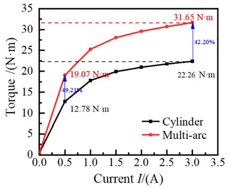
Comparison of working gap torque for shaped MRF device.
Figure 9 shows that the torque provided by the MRF brake exhibits a nonlinear increase with the current both multi-arc and traditional cylindrical working gap. Specifically, when the current increases from 0.5 to 3.0 A, the torque of the traditional cylindrical MRF brake grows from 12.78 to 22.26 N m, with a growth rate of 75.35%. Meanwhile, the torque for the multi-arc MRF brake rises from 19.07 to 31.65 N m, showing a growth rate of 65.97%. At currents of both 0.5 and 3.0 A, the torque for the multi-arc MRF brake exceeds that of the traditional cylindrical type by 49.21% and 42.20%, respectively. This indicates that, for MRF brakes of the same overall size, the multi-arc configuration provides better braking performance than the traditional cylindrical configuration.
Experimental analysis of braking performance
Experimental system
The experimental system designed to evaluate the braking performance of the multi-arc MRF brake is illustrated in Figure 10. The system primarily comprises an AC electromagnetic speed-regulating motor (YCT160-4B, 120–1200 r/min), worm gear reducer, LDN-08D speed/torque sensor (200 N m capacity, 0–4000 r/min range), DC power supply, and MCK-S dynamic torque display meter (200 N m range). During the experimental process, the multi-arc MRF brake prototype is rigidly secured to the test bench. The AC motor is then initiated and its rotational speed stabilized at 60 r/min using closed-loop control. Subsequently, the DC power supply is activated to energize the excitation coil, with current systematically adjusted from 0 to maximum while torque outputs are recorded at each intensity using the sensor-display system. This controlled approach enables direct measurement of torque-current relationships under steady-state operational conditions.

The experimental system for evaluating the braking performance of the multi-arc MRF brake: (a) physical model of MRF brake and (b) overall structure of experimental apparatus.
Experimental results
In the multi-arc MRF torque experiments, each test followed a standardized protocol: first, the motor rotational speed was stabilized at 60 r/min using closed-loop control before energizing the excitation coil; second, the coil current (the sole independent variable) was systematically adjusted across predefined increments; finally, the braking torque display was allowed to reach steady-state before recording the stabilized output. As illustrated in Figure 11, the braking torque of the multi-arc MRF brake exhibited a monotonic increase with coil current, peaking at 30.25 N m when the current reached 3 A. This experimental maximum demonstrated less than 5% deviation from theoretical predictions, indicating strong consistency between the measured trend and theoretical predictions. Minor discrepancies were primarily attributed to variations in MRF material properties and simplifying assumptions in the theoretical model, such as nonlinear rheological behaviors of the fluid.

The relationship between torque and current for multi-arc shape MRF brake.
Conclusion
This paper presents a design methodology for a multi-arc cylindrical MRF brake, which enhances braking torque by optimizing the geometry of the MRF working gap. The performance of the multi-arc cylindrical MRF brake was analyzed through experiments, theories, and the finite element method. The findings indicate that:
Keep the current in the coil constant, a larger arc radius in the multi-arc working gap leads to a lower average magnetic field strength. With increasing the current enhances the average magnetic field strength in the working gap.
At a current of 3 A in the coil, the braking torque is 22.26 N m for the traditional cylindrical MRF brake and 31.65 N m for the multi-arc device, reflecting a 42.20% increase in torque for the multi-arc device, confirming its superior performance under the same magnetic field strength.
In the multi-arc MRF torque experiment, when the number of coil turns is 200 and the current in the coil is 3 A current, the device generated 30.25 N m of torque, with 0.90 N m less than the theoretical prediction of 31.15 N m. This close agreement between experimental and theoretical results validates the accuracy of the proposed model.
Footnotes
Handling Editor: Mahdi Mofidian
Funding
The author(s) disclosed receipt of the following financial support for the research, authorship, and/or publication of this article: This research was funded by Natural Science Foundation of Chongqing, grant numbers CSTB2022NSCQ-MSX0501 and CSTB2022NSCQ-MSX1291; the Research Project of Chongqing Polytechnic of Engineering, grant number 2024KJA01004; the PhD Fund Project of Chongqing Industry Polytechnic College, grant number 2022GZYBSZK1-007; the Project of Science and Technology Research Program of Chongqing Education Commission of China, grant numbers KJZD-K202203701, KJ QN202303227, and KJQN202203210; the National Natural Science Foundation of China, grant number 51875068.
Declaration of conflicting interests
The author(s) declared no potential conflicts of interest with respect to the research, authorship, and/or publication of this article.