
Abstract
As a result of the inadequate carrying capacity and poor meshing performance of gears with a few teeth, the reasonable and optimal choice of parameters is a key step in design. Aiming at this problem, the stress equation for gear pairs with a few teeth was derived and it is discovered that the main failure mode of gears with a few teeth is pitting on contacting surface. At the same time, the results of theoretic analysis were also verified by strength test. A new optimization method of parameters which aimed at minimizing the contact stress was presented based on equal bending fatigue life at the tooth root of pinion and gear. The equation was solved by the genetic algorithm and reasonable design parameters are obtained. Tooth contact analysis based on finite element method is carried out and the results demonstrated that the method presented was an effective way to enhance the carrying capacity and meshing performance of gear pair with a few teeth. The study in this article laid a solid foundation for the further promotion of gear transmission with a few teeth.
Introduction
In general, the teeth number of gear with a few teeth is 2 to 6. In recent years, with the increasing application requirements of miniaturization, weight reduction, and the improvements of manufacturing technology, gear pairs with a few teeth are increasingly being used in aerospace, precision instruments, and other transmission devices which have large transmission ratio and special requirements for spatial position. However, gears with a few teeth are mainly used for transmitting motion rather than power due to the decrease of strength and rigidity and bad meshing performance in gear transmission with a few teeth. To improve the power of gear transmission with a few teeth, it is crucial to solve the tooth design problem to enhance the carrying capacity.
I Akira and Y Hidehiro 1 studied the radial modification of gear pair and it showed that over large radial modification coefficient would lead to pointed teeth, short tooth height, and small contact ratio which have a great effect on its carrying capacity. Chien-Fa and Chung-Biau, 2 who combined radial modification of gear with tooth profile modification of rack cutter, proposed the design and manufacturing method of gears with a few teeth that have no undercut, high contact ratio, and high strength. Tangential modification based on radial modification changes the tooth thickness of rack cutter to change tooth thickness and tooth height of machined gears, presented in Jun, 3 is a good reference for improving the bearing capacity of gear pair. However, no further research and quantization were conducted. Aiming at solving the problem of low strength of involute gears with a few teeth, in Yuehai et al., 4 the tangential and radial modifications were studied and a design method of equal bending fatigue strength was presented. In view of bad transmission performance, undercut, and other issues of gears with a few teeth, the selection of radial modification coefficients and helix angles were studied and appropriate design parameters were obtained in Pan-Feng et al. 5 These studies have solved some problems of gear transmission with a few teeth. However, the main failure mode of gear pair with a few teeth and the key factors affecting its carrying capacity were not obtained. Considering the deficiency of involute tooth profile of gears with a few teeth, some scholars proposed that arc tooth profile, LogiX tooth profile, and S-shaped tooth profile could be applied to them,6–9 which can not only change the meshing form but also improve the bearing capacity of gear pair, but complex tooth profile increases the complexity of gear manufacturing. A non-standard, optimal alternative involute gear design has been presented in Spitas and Spitas, 10 which has the same pitting resistance as the standard involute gears but exhibits maximum resistance to bending. The results indicate that optimal designs can achieve up to 8.5% reduction of the fillet stress. Other extreme design as asymmetric gear has been studied by some investigators. The basic geometric theory of the gears with asymmetric teeth has been developed in Kapelevich 11 and provided a method of research and design of gears that enables to increase load capacity, reduce weight, size, and vibration level. And Cavdar et al. 12 presented a method of computer-aided analysis of bending strength of involute spur gears with asymmetric profile. These comprehensive methodologies based on optimization theory and computer aided are efficient and useful in improving gear strength, which can also be applied in gear with a few teeth.
Based on theoretical analysis and experimental verification, the main failure mode of gear transmission with a few teeth was analyzed and the design method of tooth profile and the check theory of gear pair with a few teeth were studied in this article. In order to improve the bearing capacity of gear pair with a few teeth and reduce the contact stress, a constrained nonlinear optimization mathematical model based on the equal tooth root bending fatigue life of gears with two-way modifications was established. An exterior penalty function was adopted and the model was transformed to an unconstrained optimization problem with penalty. The genetic algorithm was used to optimize the calculation and the design parameters of tooth profile of gear pair with 4 to 60 teeth were derived. Finally, the finite element method was used to compare and analyze the results. The results show that the bearing capacity and the meshing performance of gear pair with a few teeth have been greatly improved after the optimization.
Strength analysis of gear pair with a few teeth
The main failure modes of gear transmission are pitting on contacting surface and fatigue failure on teeth. For gears with a few teeth, it is also essential to calculate contact fatigue strength and bending fatigue strength. Gear pair with a few teeth has the characteristics of pointed teeth on pinion and meshing beyond pitch point. Hence, the traditional calculating method is no longer applicable, and it is necessary to study the equation for calculating the strength. To ensure that the transmission is continuous, gears with a few teeth are generally helical. Hence, this article is based on involute cylindrical helical gear with a few teeth.
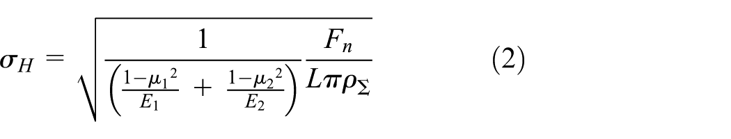
Calculation of contact stress
The traditional strength analysis of involute gear is based on the fact that pitting occurs in the section near the pitch line on one side of tooth root, and generally, the pitch point is selected to calculate the contact stress. But the contact ratio of gear pair with a few teeth is generally less than 1 and the actual meshing line is within gear pitch circle, 4 which makes the pitch point no longer suitable for calculating the contact stress. Hence, it is necessary to find the position of the meshing point with maximum contact stress in transmission process. The meshing point where the comprehensive curvature radius is the smallest is the position where the contact stress is the largest. The equation of comprehensive curvature radius is

where
The curvature of each point on the involute profile is different, and the contact stress at each point along the working tooth profile is also different. According to equation (1), the figure of comprehensive curvature along the meshing line was obtained (e.g. Figure 1). It can be seen that the meshing point
where

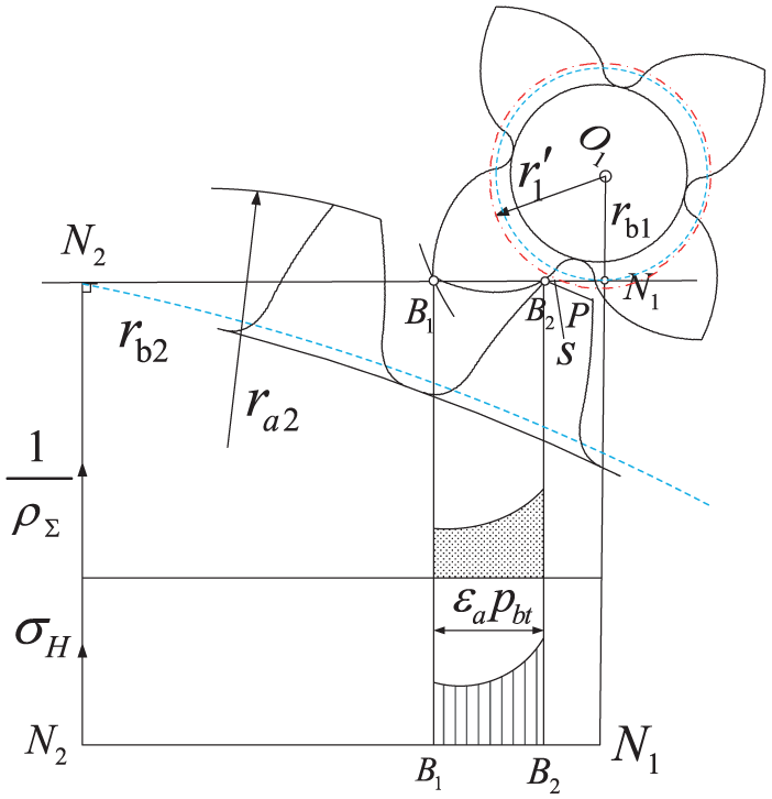
Comprehensive curvature of the meshing point.
The addendum circle of gear with a few teeth is smaller than the theoretical addendum circle calculated by the conventional formula because it is sharpened. The pressure angle

It is necessary to calculate the comprehensive curvature radius of the point


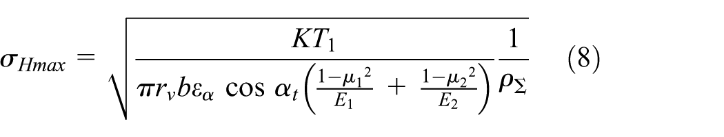
Substituting equation (7) into equation (2), the maximum contact stress can be calculated as follows
Calculation of bending stress
To calculate bending stress of involute gear pair with a few teeth, the effect of pointed teeth and tangential modification on pinion should be considered and the traditional equations for designing and calculating should be modified as well. The position of dangerous section on the root of pinion was obtained by the finite element method in Yuehai et al.
4
(e.g. Figure 2). The equations for calculating the distance from the force acting point to the dangerous section


where


Dangerous section on tooth root of pinion.
According to the stress principle of cantilever beam in Mechanics of Materials, the stress equation of tooth bending fatigue is


where
The teeth number in the figure of tooth form factor

Tooth form factor
The stress equation for bending fatigue (Figure 4) of gear is


Dangerous section on tooth root of gear.
When using

Tooth form factor
Strength analysis of gear pair with a few teeth
Using the equation for contact stress or bending stress to select parameters is determined by the main failure mode of gear pair with a few teeth; further analysis will be made here.
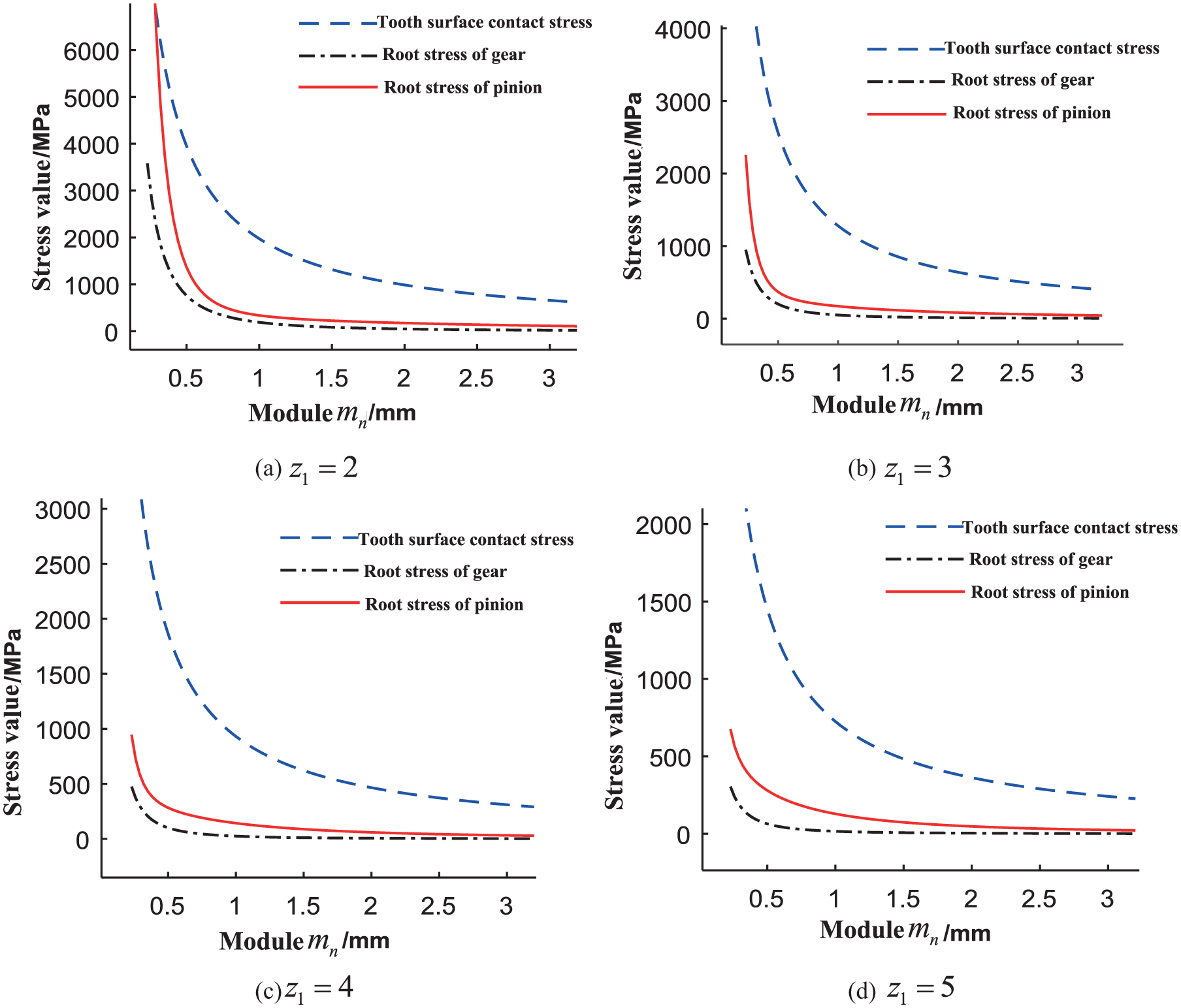
By the equations for contact stress and bending stress, the change rule of contact stress and bending stress of gear pair with 2 to 5 teeth with module is obtained (e.g. Figure 6). In the equations, the pressure angle
Strength analysis of gears with a few teeth with different modules.
By the above numerical analysis, the following conclusions are obtained:
The contact fatigue is the key factor affecting the bearing capacity of gear with a few teeth and it is the main failure mode of gear pair with a few teeth.
The tooth contact stress and bending stress increase sharply when gear module is less than 0.5.
The value of bending stress of pinion is larger than that of gear when the module value varies from 0.5 to 2.5.
In order to verify the theoretical analysis, the strength test of few teeth gear pair whose parameters are shown in Table 1 is carried out. The test-bed and test results are shown in Figures 7 and 8, respectively. Specifically, Figure 8(a) shows that micro pitting appeared on the gear teeth after 16.6 h of operating time under the test condition of 50 N m and 1000 r/min. Figure 8(b) shows that the pinion shaft with 2 teeth was broken off after 31.2 h of operating time under the same test condition. Figure 8(c) shows that wear and micro pitting appeared on the gear teeth after 28.5 h of operating time under the test condition of 60 N m and 1000 r/min.
Parameters of the test gear.


Gear strength test-bed.

Strength test results for gear pair with gear ratios of 2/60 and 4/60: (a) pitting appeared, (b) the pinion shaft was broken, and (c) teeth wear and pitting appeared.
After the test of gear pair, pitting and a small amount of bonding areas appeared on tooth surface of pinion and the shaft with 2 teeth was broken off. The teeth wear on the surface of gear was obvious and plastic deformation and bonding areas appeared on some of its tooth surface.
The theoretical analysis and experimental verification show that the contact fatigue pitting is the main failure mode of gear transmission with a few teeth. Hence, in parameters design of gear pair with a few teeth, the parameters should be selected by the equation of contact fatigue strength and the results should be checked by the equation of bending fatigue strength. The number of stress cycles of pinion is far more than that of gear because of the large transmission ratio of the pair. Hence, pinion is the weak link of the gear pair. To prevent the shaft of pinion from bending or torsional fracture, it is also necessary to check the bending and torsional strength of it.
Optimal design of tooth shape
Because of the small teeth number of pinion, the traditional design method of parameters is no longer applicable. Based on the analysis in chapter of strength analysis of gear pair with a few teeth, an optimal design that strikes a balance of tooth bending fatigue life between pinion and gear and reduces the contact stress is proposed in this article. With reasonable choice of design parameters, the bearing capacity and meshing performance of gear pair with a few teeth are improved.15–17
Design variables
The basic gear-shaped parameters are module, teeth number, pressure angle, and modification coefficient. In general, the design parameters are standardized to meet the requirements of process ease and interchangeability. In the case of given center distance and teeth number, factors affecting the design parameters are radial modification coefficient, tangential modification coefficient, and pressure angle of pinion and gear. In order to get better tooth shape to improve the bearing capacity, the optimal design variables are introduced

where
Objective function
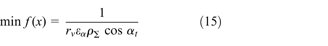
The key problem to be solved in gear transmission with a few teeth is the low bearing capacity of the gear pair. And the low contact strength of the teeth is the key factor affecting the bearing capacity. Hence, the maximum contact stress is taken as the objective function in the optimal design of gear-shaped parameters; the simplified objective function obtained by equation (8) is
Constraints
Equal tooth root bending fatigue life
For the balance of tooth bending fatigue strength of pinion and gear, the bending fatigue life of them should be equal

The stress cycles of pinion and gear within the tooth bending fatigue life are respectively


where
By the equation 17 of finite fatigue life limit and stress cycles, equations (19) and (20) are obtained


where
Then substituting equations (11), (13), and (17)–(20) into equation (16) and ignoring the effect of stress correction coefficient, the constraint of equal tooth root bending fatigue life is obtained

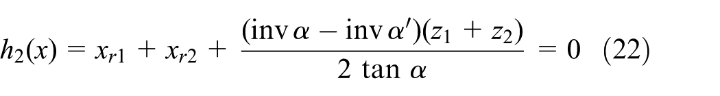
Meshing engagement without backlash
Gear pair with a few teeth is designed to satisfy the condition of meshing engagement without backlash
where
Tooth top thickness of gear
For the balance of bending fatigue life, the tooth bending strength of pinion should be improved and that of gear should be reduced. Hence, pinion has the positive tangential modification and its tooth thickness becomes larger and gear has the negative tangential modification and its tooth thickness becomes smaller, which is shown in Figure 9. To ensure that the effective meshing areas on tooth surface are no longer reduced and to avoid addendum pointing on gear, the tooth top thickness should be larger than 0. Hence, inequality constraints are constructed as follows

where

Gear with tangential modification.
Prevention of undercutting
The teeth number of pinion is generally 2 to 6 and an inequality constraint is constructed to prevent undercutting

Optimal design example
The constrained nonlinear optimization model was transformed into an unconstrained optimization problem with penalty by the exterior point penalty function. Then the problem was optimized by genetic algorithm. After constraints are processed, the optimal mathematical model of tooth profile of gear pair with a few teeth is

where
The basic parameters of gear pair with a few teeth are shown in Table 2.
The basic parameters of gear pair.

The materials of pinion and gear are both carburizing and quenching alloy steels 20CrMnTiA. The ultimate bending fatigue stress
Based on the design experience, the upper and lower bounds of each design variable are defined as
The punishment factor

The optimization results are rounded as:
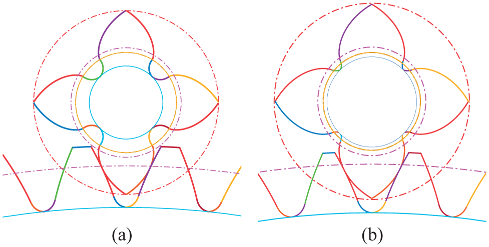
The section model of gear pair before and after optimization: (a) before optimization and (b) after optimization.
It can be seen that after optimization, the tooth height and tooth thickness of the gear with a few teeth increase. On one hand, the effective contact area of the gear pair increases; on the other hand, larger section area effectively improves the situation of severe bending and torsional deformation on pinion shaft.
To compare the contact stress on tooth profile before and after optimization, the loaded tooth contact analysis (LTCA)18–22 of the gear pair was carried out by the finite element software before and after optimization. Only the rotational degrees of freedom of pinion and gear axes were retained, the rotational angular velocity of pinion axis was set to 0.5 rad/s, and a torque of 6 N·m was applied to gear axis. Material properties: The elastic modulus

The finite element model: (a) before optimization and (b) after optimization.
The stress distributions on tooth profile before and after optimization are shown in Figures 12 and 13. It can be seen that the tooth shape optimization method is useful and effective.

Stress distribution before optimization: (a) engaging-in, (b) engaging in middle position, and (c) engaging-out.

Stress distribution after optimization: (a) engaging-in, (b) engaging in middle position, and (c) engaging-out.
The three-dimensional dynamic finite element stress analysis was conducted to obtain the transmission performance for gear pair after optimization, the torque

The axial stress distribution before optimization: (a) stress distribution of pinion and (b) stress distribution of gear.

The axial stress distribution after optimization: (a) stress distribution of pinion and (b) stress distribution of gear.

Comparison of transmission error.
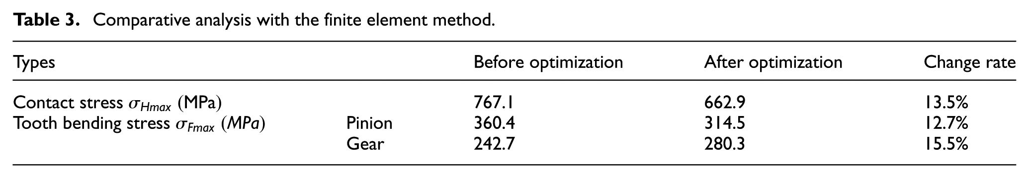
According to the above analysis and comparative analysis in Table 3, it was found that the maximum contact stress appears at the addendum of gear and the root of pinion when contact points on the edge are removed. After optimization, the contact stress of gear pair decreases effectively, and the accuracy of the point selected in 2.1 for calculating contact stress of gear pair with a few teeth is verified. With tangential modification, the tooth of gear becomes thinner; thus, it has larger flexibility to keep balance with the slender shaft of pinion which has large flexibility, even distribution of contact load on tooth surface and better meshing performance.
Comparative analysis with the finite element method.
Conclusion
Through theoretical analysis, it is found that a numerical method can be used to calculate the maximum contact stress of gear with a few teeth and the contact fatigue on tooth surface is the key factor affecting the bearing capacity and the main failure mode of gear pair, which are verified by test. A strength calculating method of gear pair is established.
An optimal mathematical model for tooth profile with the minimum contact stress on tooth surface is established under the condition of equal bending fatigue life.
An optimization algorithm is applied to optimize the design parameters in the example and LTCA is carried out by finite element method before and after optimization. The results show that the optimized gear pair with a few teeth significantly does better in enhancing bearing capacity and meshing performance, providing a method to select the parameters of gears with a few teeth.
Footnotes
Handling Editor: Davood Younesian
Declaration of conflicting interests
The author(s) declared no potential conflicts of interest with respect to the research, authorship, and/or publication of this article.
Funding
The author(s) disclosed receipt of the following financial support for the research, authorship, and/or publication of this article: The authors gratefully acknowledge the financial support provided to this study by the National Natural Science Foundation of China under grant no. 51175369.