
Abstract
To meet space science experiments in micro-gravity environment, micro-spacecraft vibration isolation technology was developed in recent years. A new kind of 2-degree-of-freedom electromagnetic actuator based on Lorentz principle was developed in this article. The composition and working principle of the actuator were introduced, the parametric model for electromagnetic actuator was established, the structural optimization was carried out with the help of genetic algorithm in the MATLAB toolbox, and the final optimal structural parameters were obtained. For achieving the magnetic induction intensity in radial and axial directions, theoretical model for electromagnetic characteristics of the 2-degree-of-freedom actuator was established, and the expression for electromagnetic force was obtained. A static electric–magnetic coupling simulation of the whole actuator and also the experiments for measuring magnetic induction and magnetic force were carried out, and the correctness of theoretical model was verified.
Keywords
Introduction
A turbulence caused by high-speed periodic motion and alternating temperature always happens to the spacecraft, and a micro-vibration with small amplitude and lower frequency was taken to the spacecraft. In micro-gravity environment, this kind of micro-vibration will cause the negative influence on the imaging quality of high-resolution observation on the earth, measurement accuracy of gravity gradient, and experimental results of micro-gravity in space. 1 More seriously, it may even lead to the failure of some space tasks. Therefore, more and more attention has been paid to the study on the technology of micro-vibration suppression and isolation.
Although the conventional contact passive isolation device has the advantages of simple structure and good reliability, it is only suitable for the isolation of medium- and high-frequency vibrations. Gravity acceleration is less than 10−3 g in the micro-gravity environment, and the vibration on the components and the equipments of the spacecraft is approximately 0.01–30 Hz of the low-frequency range. 2 The non-contact vibration isolation device can isolate the vibration of low frequency or ultralow frequency between the platform and the payload. So, it can ensure that the payloads always work in a super static environment.
As the key component of the micro-vibration isolation system, the electromagnetic actuator based on the principle of Lorentz force aroused great interest of researchers for high efficiency, fast response, high energy density, and large range of travel. At present, the research on electromagnetic actuator used in space vibration isolation has just one single degree of freedom (DOF), the research on the 2-DOF electromagnetic actuator is still in a starting stage, and the research results are very limited.
In view of the advantages of optimal distribution, low system costs, and low weight for the large vibration isolation system, the research on the 2-DOF electromagnetic actuator for micro-vibration isolation in space environment should be carried out as soon as possible.
Structural design of 2-DOF electromagnetic actuator
The actuator configuration
It can be seen from the relevant literature that most of the electromagnetic actuators are rectangular structures as shown in Figure 1(a). The direction of magnetization of the permanent magnet (PM) was shown as the solid arrow. And, the direction of the current in the coil was shown as the dashed arrow. The driving force was only generated in the wires of which the current direction was perpendicular to the magnetization direction of the PM. Although the other wires do not generate driving force, they will increase the mass and the heat consumption. In order to make the whole coil in the magnetic field play a role of driving, an improved actuator configuration composed of annular PM and annular coil is proposed as shown in Figure 1(b).

Shape and structure of actuator: (a) rectangular structure and (b) ring structure.
When the coil is energized, the current of the wire in the magnetic field is perpendicular to the magnetization direction of the PM, and the driving force can be generated by all the wires. According to the movement mode, the electromagnetic actuator can be divided into the moving coil type (MCT) and the moving magnet type (MMT). The MCT is that the moving load connects with the cell, and the MMT is that the moving load connects with the PM. The working state of the MCT coil is stable, the heat dissipation is good and the allowable current is large, but the PM is little for a light moving part leading to the magnetic field is weak. For the MMT cell, its high-frequency response is better owing to lightweight. Furthermore, much limitation of magnetic circuit design could be ignored because the PM is fixed, thus the PM is larger with high-intensity magnetic field; however, MMT’s disadvantages are (1) transmission line of cell is easy to break, (2) the heat dissipation was bad for the limitation of structure, and (3) the allowable current is little.
For determining the actuator’s configuration, different schemes are compared. For the PM array, the magnetic field in the inner space is far stronger than the outer side. In order to get a larger driving force, the coil should be placed inside the PM array. Accordingly, the design of the PM array structure based on the MCT and the MMT configuration is shown in Figure 2.

Array structure of PM: (a) moving coil type and (b) moving magnet type.
It can be seen from Figure 2 that if the gaps between the PMs and the coil of the MCT and the MMT are the same, the two structures have the same driving force, the mass of the coil of the MCT is much smaller than the MMT, and the MCT has more allowable load. When the layout of cell is designed, the parallel winding is used to reduce the heat consumption, of the coil, so the problem of heat dissipation could be solved. 3
To sum up, the MCT is taken in the design of the 2-DOF electromagnetic actuator.
The design of structure of the actuator
Based on aforementioned analysis, for presented 2-DOF electromagnetic actuator, Halbach array is adopted for PMs and parallel connection is adopted for coils in the actuator; the whole actuator uses the MCT configuration and the basic shape, and the current direction of the coil will be determined in the next step.
The magnetic field lines of the PM array of the actuator are shown in Figure 3(a). The solid arrow indicates the direction of magnetization of the PM, and the dashed arrow indicates the direction of the magnetic field in the inner space of the PM array.

Schematic diagram of 2-DOF electromagnetic actuator: (a) magnetic lines of PM and (b) force lines on energized coil.
Although the PM can significantly enhance the magnetic field strength with Halbach array, the direction of the magnetic field is changed regularly. 4 If the direction of the current in the coil is the same with the direction of magnetic field, then no magnetic force could be produced between coil and PM. Therefore, the direction of the current should be determined according to the direction of the magnetic field of the coil. When the actuator starts to work, the direction of current in the coil and the force on the coil are shown in Figure 3(b).
It can be seen from Figure 3 that current direction in the coils 1 and 2, which are applied vertical force, is opposite, so is with the coils 5 and 6; thus, the coils 1 and 2 (or 5 and 6) can be designed as a whole cyclic coil. Applied horizontal force, the current direction in coils 3 and 4 (or coils 7 and 8) is the same; therefore, the coils 3 and 4 (or coils 7 and 8) are just in the form of two half-ring coils. Based on the analysis above, the configuration of the 2-DOF electromagnetic actuator is shown in Figure 4.

Configuration of 2-DOF electromagnetic actuator: (a) breakdown, (b) profile, (c) half-ring coil, and (d) ring coil.
It can be seen from Figure 4 that the actuator is composed of the float and the stator. The float is made up of six coils (two ring coils and four half-ring coils), gaskets, and a load platform. For each ring coil, series connection is adopted in each layer, and parallel connection is adopted among layers. For each half-ring coil, only parallel connection is adopted in each layer and among layers. The stator consists the magnetic yoke, the bottom plate, and four circular PMs arranged in the arrangement of Halbach.
The magnetic yoke can form the magnetic path better and reduce the magnetic leakage. The Halbach arrangement can enhance the magnetic field intensity applied to coils. In Figure 5, the action of the actuator is based on the principle of Lorentz force.

Working principle of 2-DOF electromagnetic actuator: (a) drive in vertical direction and (b) drive in horizontal direction.
When the current in the ring coils is switched on as shown in Figure 5(a) and the other coils are not energized, a vertical Lorentz force can be generated, which can drive the float moving upward. If the direction of the current is changed, the float can be driven moving downward. In the same way, when the current in the half-ring coils is energized as shown in Figure 5(b) and the other coils are not energized, a horizontal Lorentz force can be generated, which can drive the float moving leftward. According to the above principle, the direction of current of the coils is shown in Figure 5, a compound motion of vertical motion and horizontal motion can be generated. Therefore, the actuator could have the motion of two DOFs by switching on/off the current or changing the current direction of coils.
Theoretical modeling of electromagnetic characteristics of the 2-DOF electromagnetic actuator
According to the molecular circulation hypothesis, when one PM is magnetized uniformly, the effect of molecular current in inner part of the PM is counteracted. Thus, the magnetic field at any point in the outer space of the PM can be equivalent to the excitation from the surface of the PM, so the magnetic field generated by the surface current can be equal to the space magnetic field of the PM.
The actuator in this article is composed of some ring PMs, which including two types of radial magnetization and axial magnetization. And, when the magnetic field model is built, the two types are discussed separately, then the analytical model should be obtained by superposition principle.5–8
Modeling of the magnetic field of PM in radial direction
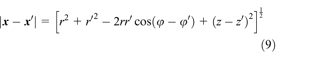
Cylindrical coordinate system is built, and the coordinate origin is located at the center of the PM. Arrows r and z denote the radius direction and the vertical direction, respectively. The magnetic field model which is generated by surface current is shown in Figure 6. In the model, inner radius is r(1), outer radius is r(2), the Z coordinate of the bottom is Z(1), and the Z coordinate of the top surface is Z(2). The initial angle is

Magnetize surface current model in radial direction.
By the theory, magnetic induction is a vector with divergence zero, so it can be expressed as a curl of a vector field. This article introduces the magnetic vector potential

The differential form of the magnetic flux’s continuity equation is known as

The differential form of ampere circuit law is known as

The definition of magnetic field intensity is

where

where
For PM with uniform magnetization, there is no equivalent volume current density inside the PM with only surface current density, so

If an infinite and uniform material is defined, Green’s function

According to Figure 6, equation (7) can be transferred as following by coordinate transformation

When equation (8) is transformed into the expression in the cylindrical coordinate, then
The component of magnetic vector potential at any point in space can be expressed as following


where Ar is the magnetic vector potential in radial direction, Aφ is the magnetic vector potential in angel direction, Az is the magnetic vector potential in axial direction,
Substituting equations (9)–(11) into equation (1), the expressions for magnetic induction intensity in radial and axial direction are


Modeling of the magnetic field of PM in axial direction
When the magnetization direction of the PM is along the axial direction, the magnetic field model can be obtained using surface current model, and it can be seen in Figure 7.

Magnetize surface current model in axial direction.
In the same way, the magnetic vector potential at any point in space in this situation can be expressed as following


where
Modeling of electromagnetic force of the 2-DOF electromagnetic actuator
According to the array model of PM, the magnetic field model based on surface current model is shown in Figure 8.

The surface current model of the actuator.
The magnetic induction intensity in radial direction of the PM1 and PM3 can be expressed as following

The magnetic induction intensity in radial direction is
In the same way, the magnetic induction intensity in radial direction of the PM2 and PM4 can be expressed as following

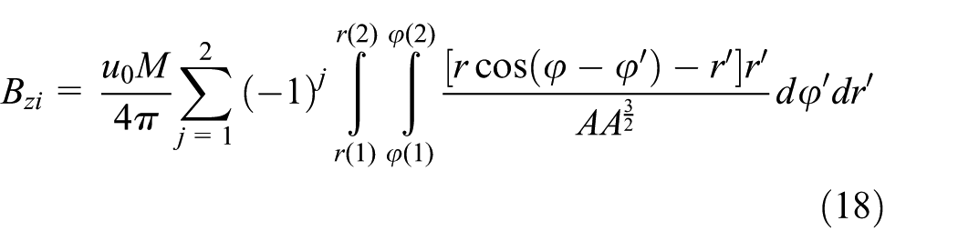
And the magnetic induction intensity in axial direction is

Therefore, for this configuration of PM, magnetic induction intensity for any point in space can be written as

where i is the number for PMs. According to the Lorentz principle, the output force of the whole actuator is as following


where Frk is the output force in radial direction, and Fzk is the output force in axial direction. Therefore, the Lorentz force for this 2-DOF actuator can be expressed as

where k is the number for coils.
Parametric modeling and optimization of the 2-DOF electromagnetic actuator
Parameterized modeling and optimization of the PM
The parameterized model and the structural parameters of the actuator can be seen in Figure 9. In Figure 9, wcoil is the width of the coil, dcoil is the inner diameter of the coil, hcoil is the height of the coil, α is the angel of the coil unit, p is the space between PM and coil, x1 is the allowable diameter of the whole actuator, and x2 is the allowable height of the whole actuator.

Parameterized model of the actuator: (a) parameterized model of coil and (b) position parameters between PM and coil.
The maximum of the radial component and the vertical component are both taken as optimization objective function with dimension constraint. So, the optimization model is as following


where Br is the magnetic induction intensity in radial direction, Bz is the magnetic induction intensity in axial direction, dm is the diameter of the magnet, hm is the height of the magnet, and wm is the width of the magnet.
According to the requirement of design, the initial value of diameter, width, and thickness are chosen as L0 = (120,15,0). The relationship between magnetic induction intensity and thickness of PM with different diameter and width values are obtained by means of MATLAB, shown in Figure 10.

Optimal structural parameters: (a) magnetic induction intensity in radial direction and (b) magnetic induction intensity in axial direction.
According to the results, the optimal parameters are chosen as L0 = (120,25,0).
Structural modeling and optimization of the electromagnetic actuator
Based on the optimal size of the PM, a size optimization is brought to the cell. The minimal mass of the cell and the minimal heat consumption are taken as optimization objective function. The relative position parameters between the PM and the coil are taken as constraints. And it is necessary to ensure that the coil is located in the magnetic field within the travel range, the optimization model is as following


Based on the genetic algorithm, the optimization is carried out by the means of the optimal toolbox of the MATLAB, and the results are as shown in Figure 11. It can be obtained that when the internal diameter of the cell is 20 mm, smaller values of the mass and the heat consumption can be obtained.

Optimization of size of coil.
Based on the above optimization, the initial values and the optimal values of the structural parameters of the electromagnetic actuator are listed in Table 1.
Initial value and optimal value of structure parameters.
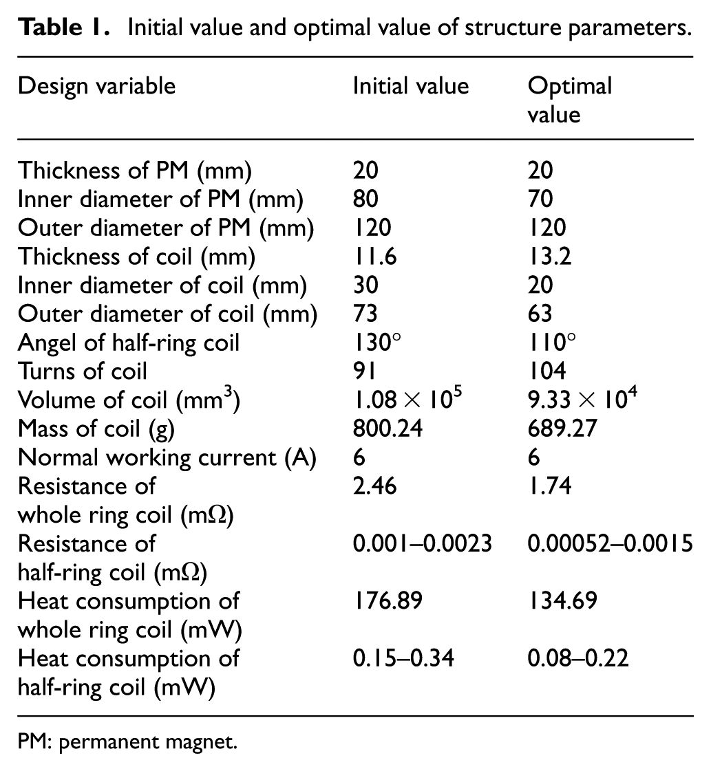
PM: permanent magnet.
It can be seen from the comparison, after the size optimization, a great reduction takes place in the mass of the cell and the heat consumption of the actuator, and the design requirements of lightweight, small size and low consumption for electromagnetic actuator are satisfied.
The static electric–magnetic coupling simulation on the 2-DOF actuator
To verify the electromagnetic model and the model of magnetic induction intensity of PM using the Halbach array, a simulation is carried out by means of Maxwell. Because the electric and the magnetism are both involved in the simulation, the solver of static magnetic field is taken for the solution of three-dimensional (3D) static magnetic field and the parameterization solution of electromagnetic force.9–11
The material of the PM is set as NdFeB, whose model is N38H in simulation software. The simulation parameters of the PM are listed in Table 2, and the simulation results of the magnetic field in the PM are shown in Figure 12.
PM material properties.

PM: permanent magnet.

Simulation of magnetic field in the PM.
The analytical values of magnetic induction intensity on track AB is calculated by MATLAB, and the comparison between analytical result and simulation result is shown in Figure 13.
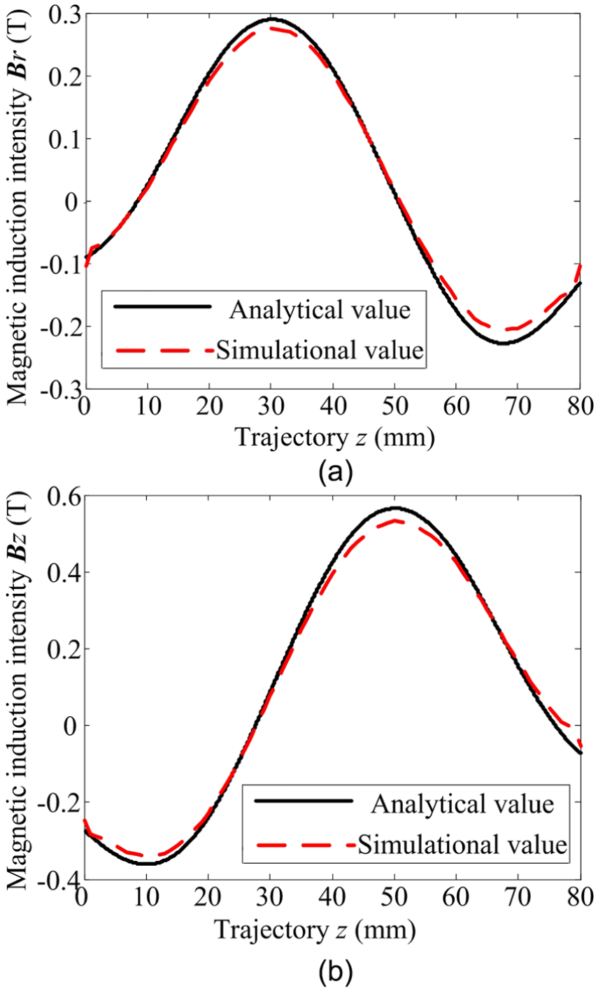
Comparison between analytical result and simulation result of magnetic induction intensity of Halbach array: (a) magnetic induction intensity in radial direction and (b) magnetic induction intensity in axial direction.
It can be seen from the comparison that the simulation results are similar to the analytical results, and the error is less than 5%. The reason is that the magnetic saturation of the PM is ignored, and the theoretical value is greater than the simulation value.
In the same way, the analytical value of the electromagnetic force on the coil is calculated by MATLAB, and it is also compared with the simulation results, which is shown in Figure 14.

Comparison between analytical result and simulation result of electromagnetic force: (a) horizontal electromagnetic force and (b) vertical electromagnetic force.
It can be seen from the comparison that the simulation results and the calculation results are similar to each other, and the error is less than 5%. The reason is that the thickness of the insulation layer and the gap between the conductors are ignored when the current density is calculated, thus the theoretical value is greater than the simulation value.
Experiment on the 2-DOF electromagnetic actuator
Test on the displacement of the 2-DOF electromagnetic actuator
The experimental prototype of the 2-DOF electromagnetic actuator is developed as shown in Figure 15.

Prototype of 2-DOF electromagnetic actuator: (a) prototype of stator and (b) prototype of float.
The stator of the actuator is shown in Figure 15(a), which is composed of the PM, the magnetic yoke, and the bottom plate. The material of the magnetic yoke is pure iron for the good magnetic properties. The material of the bottom plate is aluminum alloy for its low density. The float of the actuator is shown in Figure 15(b), which is composed of the coil, the gasket, and the load platform. The material of the gasket and the load platform was the PEEK, which has high temperature resistance and wear resistance, and at the same time the, eddy current can be eliminated by the PEEK.
The environmental simulation of micro-gravity is carried out by the suspension method for the working prosperity in the space of the actuator. The gravity compensation device and the displacement test platform are shown in Figure 16.12,13

Displacement test platform.
The vertical displacement and the horizontal displacement of the actuator testing using this platform are as shown in Figures 17 and 18, respectively.

Experimental results of vertical displacement: (a) upward movement and (b) downward movement.
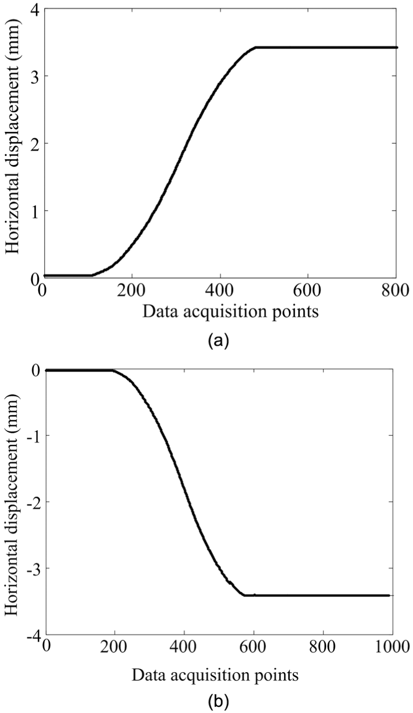
Experimental results of horizontal displacement: (a) right movement and (b) left movement.
It can be seen from the experimental results that the design requirement that the displacements of the electromagnetic actuator in horizontal direction and in vertical direction are both 3 mm is satisfied. Meanwhile, the 2-DOF motion of the actuator can be controlled by the break and the direction change of the current in the cell.
Test on the magnetic induction intensity
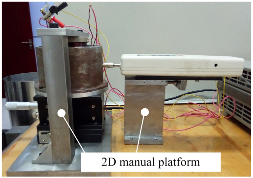
In order to test the performance of PM array, the test on the magnetic induction intensity is carried out. Meanwhile, the electromagnetic model in this article is verified further. The stator of the actuator is fixed on a two-dimensional (2D) manual platform. Accuracy of the manual platform is 0.01 mm, and the allowable load is 15 kg, which is satisfied to the requirement. The digital Gauss meter BST200 is used, of which the accuracy is 0.1 mT and the range is 2T. The whole test device is shown in Figure 19.

Test device of the magnetic induction intensity.
The experimental results are compared with the theoretical/simulation results, as shown in Figure 20. It can be seen that the three results have the same trend, and the experimental result is a little less than others, especially in the two ends of the PM array, maximum of which is 8%. The sources of error are relative position error of sensor pen and PM, gap between PMs, and magnetic leakage of PM.
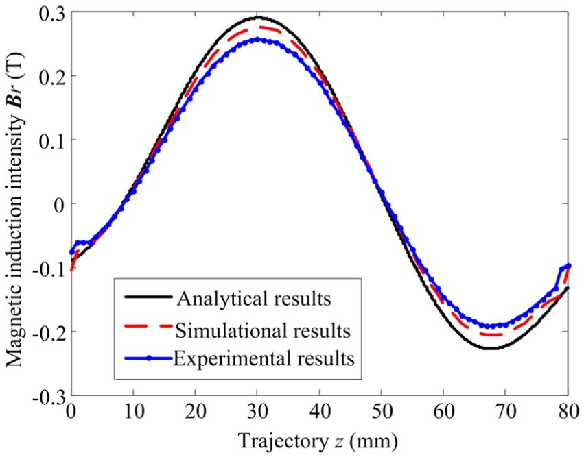
Comparison among theoretical results, simulation results, and experimental results of magnetic field distribution of PM.
Test on the electromagnetic force of the 2-DOF electromagnetic actuator
Test on the electromagnetic force in vertical direction
Force output is an important performance index for the electromagnetic actuator, a test on the electromagnetic force should be carried out.
The test device is composed of push–pull meter, displacement platform, and magnetic seat, which is shown in Figure 21.

Test device for force in vertical direction.
The float is fixed on the 2D manual platform. Load platform of the float contacted with stressed end of the push–pull meter. The measurement direction should be through the center of the float. Otherwise, there will be an additional torque. The push–pull meter is fixed on the magnetic seat, of which the accuracy is 0.001 N and the range is 500 N.
The relationship between the force in vertical direction and the relative displacement is tested, and the simulation results and the theoretical results are both shown in Figure 22.

Comparison among theoretical results, simulation results, and experimental results of force in vertical direction.
It can be seen that the three results are similar to each other basically, and the error among them is about 7%. The reasons to the error may be the force on the meter on the other directions or the displacement error between the stator and the float.
Test on the electromagnetic force in horizontal direction
During the test of the electromagnetic force in horizontal direction, the stator of actuator is fixed and contacted with stressed end of the push–pull meter. In the same way, the measurement direction should be through the center of the stator. The device is shown in Figure 23, and the experimental results are shown in Figure 24.
The device of test force in horizontal direction.
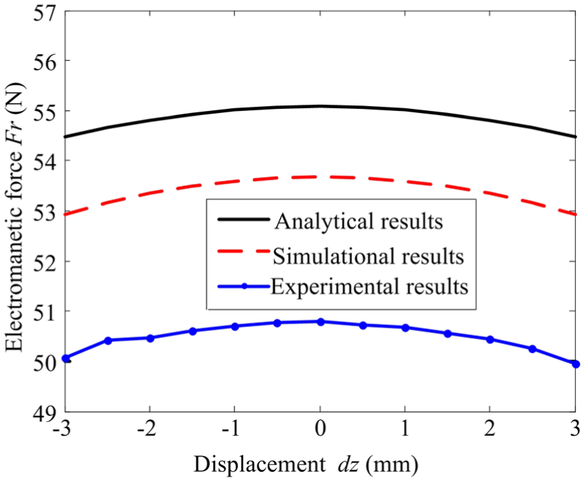
Comparison among analytical, simulation, and experimental results of force in horizontal direction.
It can be seen that the three results are similar to each other basically, and the error among them is less than 8.5%. The reasons to the error may be the error of the friction or the displacement error between the stator and the float.
It can also be seen from the experimental results that the electromagnetic forces in the horizontal direction and the vertical direction are both more than 50 N. And, the requirement of design was stratified. And, the theoretical model was verified because the experimental result of the electromagnetic force tails with the theoretical result.
Conclusion
As the traditional passive exposure to low-frequency vibration isolation effect is not obvious, a kind of 2-DOF electromagnetic actuator based on the Lorentz principle. The conclusions of this article are summarized as follows:
By considering overall size, output characteristics, and heat consumption of the actuator, the structure of the PM based on the Halbach array and structure of the coil based on the parallel connection were presented. By a comparison between the rectangular structure and the annular structure, a comparison between the MCT configuration and the MMT configuration, the configuration of the 2-DOF electromagnetic actuator was determined.
The optimization model was established based on the effect on the performance by the structural parameters. And, the optimal structure parameters are obtained by optimizing the size of the actuator on the minimum of the coil mass and the minimum heat consumption.
Based on the molecular circulation hypothesis, the surface current model of the PM is established, and the analytical expressions of the magnetic induction intensity and the electromagnetic force of the 2-DOF electromagnetic actuator were derived. The finite element simulation of the magnetic field distribution and the electromagnetic force of the actuator were carried out, and the electromagnetic model was verified.
The experimental prototype of 2-DOF electromagnetic actuator was developed. And, a gravity compensation method was proposed. Through the experiment of actuator displacement tests, the requirement of indicators was satisfied. Through the experiment of electromagnetic force and magnetic induction intensity, the analytical models were verified.
The 2-DOF electromagnetic actuator in this article was still in the preliminary stage. There are some limitations which can be seen from the experimental results, and following studies need to be carried out in the future work:
An improved electromagnetism model considering magnetic flux leakage, magnetic coupling, and magnetic saturation should be developed.
Active control method and strategy on the electromagnetic actuator should be developed.
Footnotes
Acknowledgements
The authors thank the anonymous reviewers for their valuable suggestions in improving this paper and the future work.
Handling Editor: Seiichiro Katsura
Declaration of conflicting interests
The author(s) declared no potential conflicts of interest with respect to the research, authorship, and/or publication of this article.
Funding
The author(s) disclosed receipt of the following financial support for the research, authorship, and/or publication of this article: This work was supported by the China Postdoctoral Science Foundation Funded Project (2015M580268), the Heilongjiang Postdoctoral Science Foundation Funded Project (LBH-Z15077), the Fundamental Research Funds for the Central Universities (grant no. HIT.NSRIF.201637), Self-Planned Task (no. SKLRS201614B) of State Key Laboratory of Robotics and System (HIT), and National Natural Science Foundation of China (grant no. 51475117).