
Abstract
Therapeutic exercises play an important role in physical therapy and rehabilitation. The use of robots has been increasing day by day in the practice of therapeutic exercises. This study aims to design and control a novel robotic platform named DIAGNOBOT for diagnosis and treatment (therapeutic exercise). It has three 1-degree-of-freedom robotic manipulators and a single grasping force measurement unit. It is able to perform flexion–extension and ulnar–radial deviation movements for the wrist and pronation–supination movement for the forearm. The platform has a modular and compact structure and is capable of treating two patients concurrently. In order to control the DIAGNOBOT, an impedance control–based controller was developed for force control, which was required for the exercises, as well as a proportional–integral–derivative controller for position control. To model the resistive exercise, an angle-dependent impedance control method different from traditional methods has been proposed. Experiments were made on five healthy subjects and it has been demonstrated that the proposed robotic platform and its controller can perform therapeutic exercises.
Introduction
Rehabilitation is a treatment process aimed at helping people with physical or anatomical disabilities. These disabilities might be congenital or may have occurred due to an accident, injury, or illness, and this treatment process aims to help such people achieve the highest possible level of functionality in the medical, vocational, and social spheres. Rehabilitation allows disabled people to participate in life at the highest possible level. 1 Due to the increasing world population, the need for rehabilitation is also increasing. Individuals with several limbs injured due to age, war, traffic or work-related accidents, or chronic diseases need rehabilitation to achieve full or partial recovery. A wide range of medical methods and treatments have been developed to refunctionalize these limbs, improve their range of motion (ROM) and muscle strength. Therapeutic exercises, one of these methods, play a crucial role in the process of restoring refunctionality for disabled limbs. Therapeutic exercises have two types: passive and active. These exercises can be performed by a physiotherapist or the patient himself.
There are several difficulties and limitations involved in the rehabilitation process, such as an inadequate number of doctors and physiotherapists per patient in highly populated countries, the difficulties suffered by bedridden and aged patients in reaching hospitals, the cost of the rehabilitation process, the duration of the treatment, and keeping a log and following up on the treatment process. According to a report by the Turkish Ministry of Health, the number of physiotherapists per 100.000 people in Turkey is four. 2 The highest number of physiotherapists is in Finland, with 202 physiotherapists per 100.000 people. Because of these reasons, the number of studies on rehabilitation robotics has seen an increase over the last two decades. 3
Upper limb rehabilitation robots can be classified in terms of mechanical structure, movement capacity, variety of exercises, and control methods. The existed systems can perform one or some of the following exercises: the passive, the resistive, and the active assistive. The control methods commonly used in robotic rehabilitation are as follows: conventional control approaches, such as proportional–derivative (PD) or proportional–integral–derivative (PID), torque control, admittance control, and impedance control.
The MIT-MANUS is a well-known robotic system used for upper limb rehabilitation. 4 The system has 3 degrees of freedom (DOFs) and can perform the passive, the active assistive, and the resistive exercises. The control method of the system is impedance control. Reinkensmeyer et al. 5 designed a 4-DOF robot, named Assisted Rehabilitation and Measurement Guide (ARM-Guide), for the rehabilitation of the shoulder and the elbow. PD position control and torque control methods were used in the system. The REHAROB was designed using a 6-DOF industrial robot. 6 The robot can perform passive exercises for decreasing the spasticity in the shoulder, the elbow, and the forearm. In their study, Fraile et al. 7 designed a 2-DOF planar robotic platform, called E2Rebot, for upper limb rehabilitation in patients with neuromotor disability caused by a stroke. Besides these studies, there are many other examples of rehabilitation robots.8–13
A 6-DOF exoskeleton robot was developed by Nef and Riener 14 for the rehabilitation of the elbow and the shoulder. The robot can perform passive- and active-assisted exercises. The control method of the system is admittance and impedance control. The use of such exoskeleton robots in rehabilitation is becoming more and more commonplace, and there are a big number of studies cited in the literature.15–29
As seen in the literature, many robots have been developed for the rehabilitation. These robots have some limitations. These limitations are DOF, independency of operating of axes, grasping of end-effector (handle), and inability for diagnosis. First, robotic manipulators have one or more DOFs in a single structure. This leads to limitations both in the control of the system and in the force and torque measurements to be made for each axis for diagnosis. Second, the failure of one of the axis also affects other axes. These robots allow for the treatment of only one patient at the same time. Third, in the previous designs, the patients grasp the end-effector. This way is not effective in stroke patients who cannot grasp. Finally, existed designs are not suitable for diagnosis.
To overcome these limitations, a novel robotic platform has been developed in this study. The developed system called DIAGNOBOT consists of three 1-DOF robotic manipulators and a single grasping force measurement unit. The most important feature of this system is that it can perform diagnosis and treatment simultaneously. For this purpose, it is equipped with sensors and actuators developed in a suitable mechanical structure. The force and torque sensors are located in the direction of movement. The robot manipulators for each movement were placed on a rotating table. Each unit can easily be removed and installed. It ensures that the robotic system is modular and configurable. Because the units are independent of each other, it allows for the treatment of two patients at the same time. Thanks to this design, the failure of a unit does not affect other units. The robot manipulators are designed according to stroke patients and they do not need to grasp manipulators (handles). The developed system can perform flexion–extension and ulnar–radial deviation movements for the wrist, and pronation–supination movement for the forearm. It can perform the passive, isometric, isotonic, and resistive therapeutic exercises. DIAGNOBOT controller has a force-based impedance control structure for the isotonic exercise. For variable resistive exercises, a novel impedance–based control method has been developed. In this method, the force on the end-effector changes depends on the joint angle. Therefore, this new control approximation is called the angle-dependent impedance control. This method’s efficiency has been confirmed through experiments made with five healthy subjects. On the other hand, PID control was used for the passive exercise.
There are two contributions to the literature in this study. The former is the unique design of the robotic platform both diagnosis and treatment for upper limb rehabilitation, the latter is the development of a controller based on angle-dependent impedance control to model resistive exercises. An explanatory video about the developed system can be reached in the link. 30
This article is organized as follows: the theory of upper limb rehabilitation is specified first, followed by the mechanical design, electronics hardware, strength and limitations, the dynamics, and the control and operation, respectively. Finally, the results and the conclusion are given.
Theory of upper limb rehabilitation
Therapeutic exercises are performed to improve the strength, endurance, coordination, speed, and skills of the limbs. They can be passive or active and can be performed manually or by an assistive device. Therapeutic exercises are considered as one of the important stages of the physical therapy and rehabilitation. In this study, the therapeutic exercises are performed for the rehabilitation of the wrist and the forearm.
Movements of limbs
The developed rehabilitation robot can perform flexion–extension and ulnar–radial deviation movements for the wrist, and pronation–supination movements for the forearm. The definitions of these movements are given in Figure 1 and explained below.
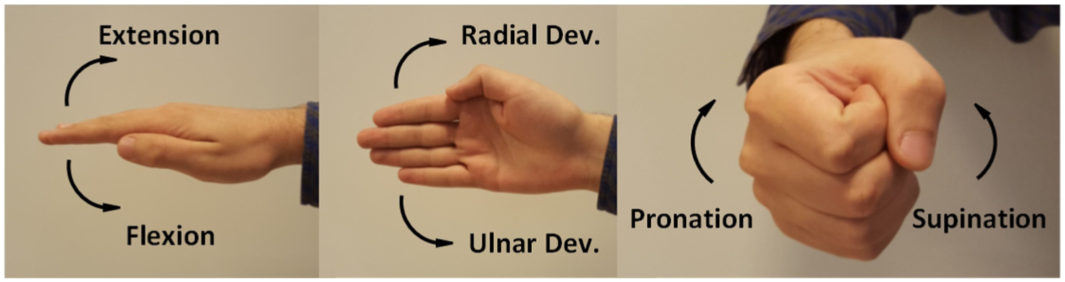
The movements of the wrist and the forearm.
Flexion–extension
Bending the wrist upward is called the extension and downward the flexion movement. The wrist is initially parallel to the ground and the palm faces downward.
Ulnar–radial deviation
Bending the wrist upward is called the radial deviation and downward the ulnar deviation movement. The palm faces sideways with the thumb in natural position.
Supination–pronation
Supination is the rotation of the forearm so that the wrist faces up. When it faces downward, it is called the pronation movement.
Types of therapeutic exercises
The rehabilitation robot developed in this study can perform the passive, isometric, isotonic, and resistive therapeutic exercises for the upper limb. The definitions of these exercises are given below.
Passive exercise
The passive exercise is performed manually or by assistive device within the motion range of the limb. It does not include the coordinated voluntary muscle contraction of the patient.
Isometric exercise
Through this exercise, the level of muscle contraction is increased without causing a change in the length of the muscle. It can be performed by pressing a stationary object, opposing the manual act of the physiotherapist, or by holding a weight in a static condition.
Isotonic exercise
In the isotonic exercise, the limb is moved along the ROM against a constant force. Additionally, an exercise mode, in which the various difficulty levels are determined by the impedance control parameters, was created in this study. This mode is called the vario-resistive exercise mode.
Design of DIAGNOBOT
This section highlights design aspects, including functional requirements and design parameters, the mechanical structure, the electronics hardware, and strength and limitations of the DIAGNOBOT.
Functional requirements and design parameters
The functional requirements of the DIAGNOBOT are as follows:
Perform the movements of flexion–extension, ulnar–radial deviation, and pronation–supination for the wrist and the forearm.
Measure the grasping force of the hand and angle of wrist and forearm for diagnosis.
Perform the passive, isotonic, isometric, and vario-resistive therapeutic exercises.
Treat two patients at the same time.
Make it possible to fix the wrist in the pronation–supination movement.
Adjust the length of each manipulator according to the size of the limb.
Provide safety via software and hardware.
The design parameters that meet the functional requirements are as follows:
There are three 1-DOF robot manipulators for each movement.
There is a grasping force measurement unit.
There are three servo motors for the therapeutic exercises required force and position control.
The robot manipulators are placed on the rotary table that allows simultaneous use.
There are two clamping screws on the pronation–supination unit.
Each manipulator can be adjusted with screws and pins in accordance with the size of the limb.
The system has three safety layers in terms of mechanical, electronics, and software.
Mechanical structure
The general structure of the DIAGNOBOT and its units are shown in Figures 2 and 3. The arm of the patient is placed in the arm clamping unit and fastened between the jaws actuated by the stepper motor. All units are placed on the rotary table. According to the type of movement, the relevant unit turns in front of the patient. The rotary table and the stepper motor that actuates the arm clamping unit are controlled by the buttons on the control panel. There is an emergency button on this panel. In front of the patient, there is a patient monitor, showing the games and directions of the exercises. There are mechanical limitation holes and pins at each unit for safety. The ROM of the manipulator can be adjusted for any patient and exercise by inserting the pins into the holes. For all manipulators, the clockwise is the positive direction and the counter-clockwise is the negative direction. The details about the units are given below.
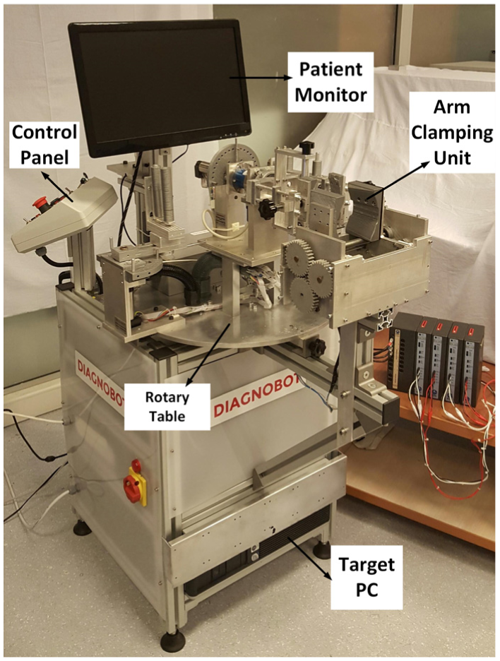
The general structure of DIAGNOBOT.

The units of DIAGNOBOT.
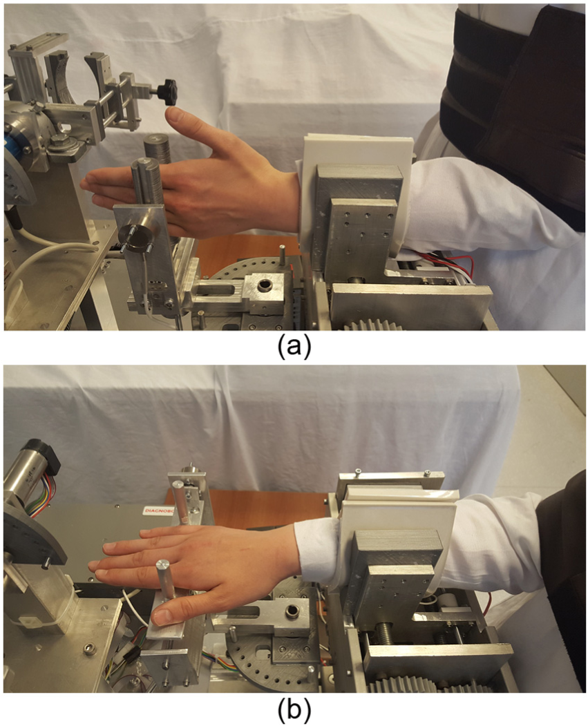
The pronation–supination unit is shown in Figure 4. This unit performs the movement of pronation–supination for the forearm. It contains a servo motor for actuation and a torque sensor for the measurement of the joint torque. The patient can be fixed to this unit in two ways. The first is, the patient grasps the removable handle with his or her hand. This is not possible in stroke patients and patients who cannot grasp. The second way is fixing of the patient’s wrist. In this way, the handle is removed. The patient’s wrist is fixed between the jaws of the unit through the clamping screws. There are rubber pads on these jaws to avoid causing any pain. In the pronation–supination movement, the arm is not fixed by the arm clamping unit. The two types of the fastening can be seen in Figure 5.

The structure of the pronation–supination unit.

The fixing to the pronation–supination unit: (a) grasping the removable handle and (b) fixing the wrist of patient.
The flexion–extension and ulnar–radial deviation units are shown in Figure 6. These units perform movements of the wrist. Each unit contains a servo motor for actuation and a force sensor for the measurement of the joint force. The patient’s hand is placed between the bars of the handle. In the flexion–extension and ulnar–radial deviation movements, the patient’s arm has to be fixed with the arm clamping unit.
The flexion–extension and ulnar–radial deviation units: (a) the movement of the flexion–extension and (b) the movement of the ulnar–radial deviation.
The grasping force measurement unit can be seen in Figure 7. The grasping force is the major measurement for the diagnosis. This unit measures the grasping force of the patient. The unit contains a force sensor to measure the grasping force.

The grasping force measurement unit.
Electronics hardware
The block diagram of the electronics hardware is shown in Figure 8. The doctor is the main user of the system. He enters all the information relevant to the therapy. There are three computers in the system: the Main PC for running the algorithms, the Target PC for real-time operations, and the Raspberry Pi for games of isometric, isotonic, and vario-resistive exercises. The algorithms were developed in MATLAB R2017a. The Simulink® Real Time is used for the real-time prototyping. The TCP/IP protocol is used for the communication between the Main PC and the Target PC. The communication between the Main PC and the Raspberry Pi is provided by UDP Protocol.

The block diagram of the electronics hardware.
There are three servo motors (Maxon EC-Max 30) with the 103:1 reduction ratio and 500 pulse/rev encoders. There are also three servo motor drivers (Maxon EPOS 2 50/5) in the system.
There are three force sensors and a torque sensor in the system. Two Burster 8523-200 force sensors are used to measure the patient force in the flexion–extension and ulnar–radial deviation units. The Burster 8627-5710 torque sensor is used in the pronation–supination unit. The Loadstar RSP1-050M force sensor is used to measure the grasping force. The measurement ranges of each sensor are given in Table 1.
The measurement ranges of the sensors.

In the system, for the encoder input and analog input/output data, Measurement Computing PCI QUAD04, NI PCI-6024E, and NI PCI-6040E data acquisition cards are used with 1-ms sampling time, respectively.
Safety is extremely important for robots that interact with humans. Therefore, various mechanical, electrical, and software-based safety measures are integrated into the developed system. They are given as follows:
Each manipulator’s ROM is in line with the ROM of the joints.
Each servo motor has current limitation.
There is a current leakage relay.
There are two emergency stop buttons for the patient and the doctor.
The high-voltage (220 V) connections are located in the insulated enclosure.
Each manipulator has software-based limitations.
Strengths and limitations
The developed robotic platform has a number of strengths and limitations. It has a modular structure thanks to the exchangeable units. The failure of a unit does not affect the other units. This is very convenient for force/torque and ROM measurements for diagnostics. It provides home-based robotic rehabilitation for bedridden and elderly patients. On the other hand, there are limitations such as the lack of motivation and confidence for patients who are accustomed to traditional methods.
Dynamics of DIAGNOBOT
Obtaining the mathematical model of the robot manipulator is very important for the control. The dynamic parameters must be calculated correctly to achieve a good control performance in the impedance control method. In this section, dynamic equations are obtained and the dynamic parameters of the system are calculated using the experimental robot identification through the optimized periodic trajectories method. 31
The single-link robot manipulator’s dynamic equation is shown in the following equation

where
System identification and parameter estimation
The inverse dynamics of equation (1) can be expressed by following equation

In this equation, the robot position, velocity, and acceleration are the known parameters. The vector
However, there are errors in the measurement of the speed and the acceleration of the link and the robot torque. For this reason, more than six different points are used and it is ensured that the robot manipulator follows a predetermined trajectory through a PID controller. Consider we have observations data (


The condition number of the matrix


where

where


The optimal trajectory.

The optimal trajectory, position of manipulator, and error.
The obtained dynamic parameters are given in Table 2.
Estimated parameters for each manipulator.

Control and operation of DIAGNOBOT
The basis of the robotic rehabilitation is the human–machine interaction. The impedance control method developed by Hogan is the most suitable control method for this interaction.32,33 The impedance control method can perform based on position and force control. Therapeutic exercises require force and position control. The PID control, force-based impedance control, and angle-dependent impedance control, which is proposed in this study, are used in the developed robotic platform.
Angle-dependent impedance control
The dynamic behavior of the robot manipulator after applying force-based impedance control can be explained as follows

where

where


Equation (13) yields this result

where

The relationship between the joint angle and the joint force/torque was examined in the experiments with 10 healthy subjects. The results for the pronation-supination are shown in Figure 11.

The wrist torques depending on the joint angles: (a) the relationship between the supination torque and ROM and (b) the relationship between the pronation torque and ROM.
As a result of the experiments, it is seen that there is an inverse relationship between the joint torque and the joint angle. As the ROM increases, the torque produced by the joint decreases. This result should be taken into consideration in order to improve the performance of the resistive exercises.

The change of

When

When the
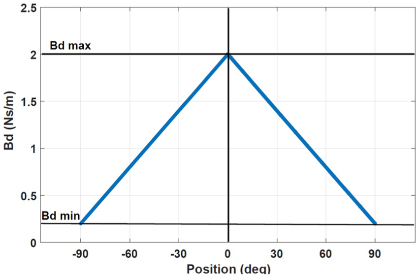
The relationship between position and
The resulting control law after combining equations (15) and (18) becomes

PID control
The PID algorithm is described by
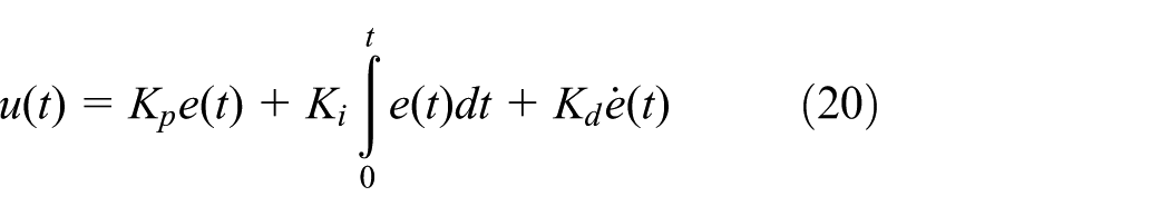
where
Verification of dynamic parameters
The
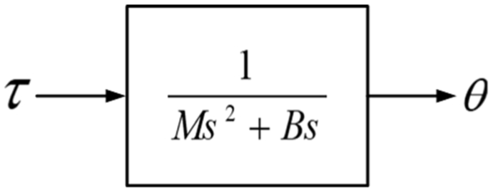
The transfer function block of the inertia–damper system.
A control model was created using MATLAB Simulink according to equation (15) and the torque manually applied to the end-effector of the robot manipulator. The

The comparison of the experiments and the simulation results: (a) experiment and simulation result in supination and (b) experiment and simulation result in pronation.
According to the simulation results, the position error between the experiment and simulation is smaller than
Human–machine interface
The HMI provides the communication between the doctor, the patient, and the DIAGNOBOT. The HMI consists of the main controller, the graphical user interface (GUI), the PID controller, and the impedance controller. The main controller is responsible for the communication between all of the units. The doctor enters the exercise information and parameters through the GUI. According to the exercise information, exercise parameters are sent to the PID or impedance controller. In addition, the trajectory and target force information for a certain type of exercise is also sent to the related controller. At the end of each exercise, the information about the session, such as the type of the exercise, the ROM, the force/torque values, the grasping force measurements before and after the treatment, and the performance evaluation of the exercise, is recorded in the database.
The passive, isotonic, and isometric exercises are performed by the HMI interface. In addition to these conventional exercise types, a novel exercise mode, named vario-resistive exercise, was developed in this study. Detailed explanations as to the exercise types are given in the next section.
Evaluation and results
The performance of the system is tested by voluntary subjects. The tests were performed under the supervision of a doctor. The passive, isotonic, and vario-resistive exercises were performed by five healthy subjects. The physical properties of the subjects are given in Table 3. The input data according to the type of exercise were entered by the doctor via GUI. All movements were repeated five times. A snapshot of an experiment with a healthy subject is given in Figure 15. The results of the experiments are presented in the following subsections.
Physical properties of the subjects.


An experiment with a healthy subject.
Passive exercise
In the passive exercise, the robot manipulator moves the patient’s limb within the ROM defined by the doctor. The position trajectory is generated by HMI according to the information entered on the speed and the motion limits. The doctor also enters the type of movement and the number of repetition from the GUI. This exercise requires position control, and the controller is in the PID control mode. An example of graphical results can be seen in Figure 16. According to the results of the experiments, the robot manipulator was able to track the desired trajectory with a margin of error below

Passive flexion–extension exercise result for subject A.
Isotonic exercise
In the isotonic exercise, the subject moves his limb against an opposing force generated by the robot manipulator. The robot manipulator resisted to the motion of the subject by applying the opposite force defined by the doctor. When the patient exceeds this target force value, the robot starts moving. If the limb force drops below this target force value, the robot forces the joint to move in the opposite direction. The controller is in the force-based impedance control mode. An example of graphical results can be seen in Figure 17. It is understood that the robot manipulator can perform the isotonic exercises.

The isotonic flexion–extension exercise result for subject B.
Vario-resistive exercise
This exercise differs from traditional resistive exercises. In our proposed mode, the resistance changes depending on the joint angle. Thus, the patient does not have difficulty increasing the joint angle and can perform the exercise highly successfully. The controller is in the angle-dependent impedance control mode. The results of the vario-resistive exercise for pronation–supination can be seen in Figures 18 and 19. The exercises were performed with different damping
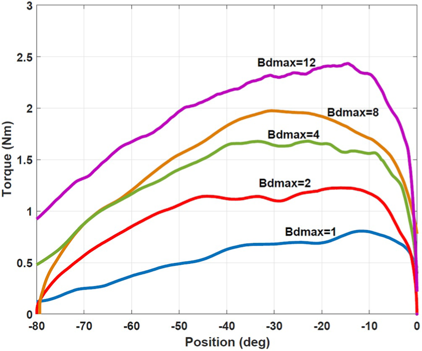
The vario-resistive therapy results at different

The vario-resistive therapy results at different
Isometric exercise
In this type of exercise, the patient tries to reach the target force while the end-effector is stationary. The doctor enters the type of movement, the target force/torque, and the starting position. At the beginning of the exercise, the robot manipulator moves to the starting position. In this position, the patient applies a force to the manipulator. The patient follows his or her force value and target force value from the game screen. In the developed game, the patient tries to reach the target position with the ball moving according to the limb force. This exercise requires position control to move the target position. Because of that, the PID controller was used. The game screen is shown in Figure 20.
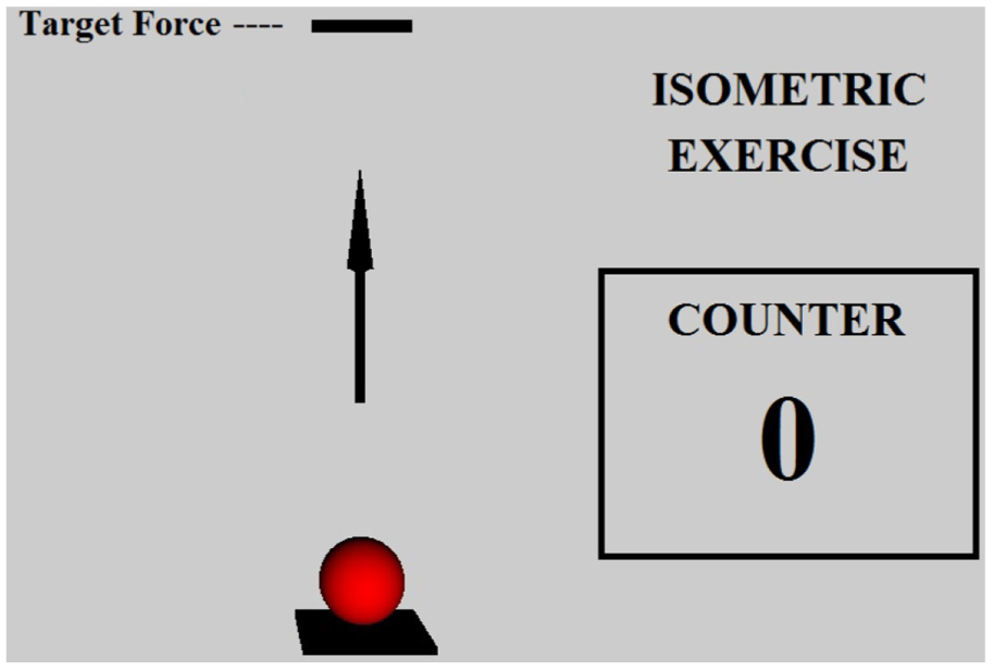
The game screen of the isometric exercise.
Conclusion
In this study, a novel robotic platform named DIAGNOBOT was designed and controlled to perform diagnosis and treatment in wrist and forearm rehabilitation. An impedance controller and PID-based controller were developed to control the DIAGNOBOT. The developed controller consists of an angle-dependent impedance controller designed for modeling resistive exercises that differ from traditional methods normally used for modeling resistive exercises. This controller was tested with five healthy subjects. Experimental results show that the developed controller can model resistive and passive exercises accurately. In order to further this study, the system will be tested with more data from healthy subjects and patients. Furthermore, the developed intelligent diagnosis and treatment control structure will be introduced. In particular, there will be greater focus on deep learning algorithms for diagnosis.
Footnotes
Acknowledgements
The authors would like to thank Prof. Dr. K. Banu Kuran and Dr. Ahmet Taha Koru for their valuable contributions.
Handling Editor: Tadeusz Mikolajczyk
Declaration of conflicting interests
The author(s) declared no potential conflicts of interest with respect to the research, authorship, and/or publication of this article.
Funding
The author(s) disclosed receipt of the following financial support for the research, authorship, and/or publication of this article: This work was supported by Research Fund of the Yildiz Technical University (project number: 2015-06-04-DOP01).