
Abstract
This article presents a thermo-mechanical coupled dynamic model for high-speed motorized spindles. The proposed model includes an angular ball bearing model, a thermal model, and a rotor dynamic model. The coupling relationship among these submodels is analyzed, and a solution procedure for the integrated model is designed. Based on the proposed model and solution procedure, the dynamic behaviors of the spindle system and the effects of the thermal displacement of the system on the behaviors are quantificationally discussed. Finally, an integrated dynamic test is carried out on a D62D24A-type motorized spindle, and the good agreement between the mathematical results and the experimental data indicates that the proposed model is capable of accurately predicting the dynamic properties of motorized spindles, and the accuracy of the model is improved when considering the thermo-mechanical coupled factor. The conclusions are useful for the dynamic design and the thermal compensation control of high-speed motorized spindles.
Introduction
The high-speed motorized spindle combines the motor, transmission, actuator, and control system, which achieves the “nearly zero transmission.”1,2 It is an intelligent unit part and includes the technologies of bearing, cooling, lubrication, drive, rotor dynamics, and so on. With the compact structure and low-cost maintenance, high-speed motorized spindle is widely used in the fields of machine, electron, aerospace, defense, metallurgy, food, chemistry, medicine, and optics, especially advanced manufacturer. 3 As the core equipment in computer numerical control (CNC) machine tools, its dynamic behaviors directly influence the machining accuracy and efficiency, while the built-in motor increases the difficulty of predicting the dynamic behaviors of the spindle system. 4 Therefore, it is necessary to optimize the dynamic characteristics of motorized spindles.
Due to the built-in motor, the heat generation of motorized spindle is larger than that of general spindle system. 5 The temperature rise not only decreases the work life of the bearing and built-in motor but also affects the machining error. 6 Therefore, motorized spindle is a thermo-mechanical coupled system a lot of researches focused on the dynamic behaviors of the system.
A Palmgren 7 established a heat generation model for ball bearings, and TA Harris 8 modified the model with the influence of the spinning moment of the ball. Based the improved model, B Bossmanns and JF Tu 9 investigated the thermal characteristics of the spindle system with finite difference method and accomplished the thermal simulation and test with the heat transfer network method. The aforementioned bearing heat generation models are based on the experiential formulas of the friction and lubrication, which fails to reflect the inner dynamic behaviors of the ball bearing. Jorgensen 10 calculated the friction moment and power loss of the bearing with the quasi-static mechanics model and discussed the influence of working parameters on the temperature rise of the system based on the heat transfer network method. M Xu et al. 11 constructed a thermal finite model for grinding motorized spindle with the consideration of the thermal contact resistance between the bearing and the pedestal and obtained the great gradient temperature of the system. XA Chen et al. 12 also established the power flow model for motorized spindles to analyze the bearing and motor heat generation, and the precision and robustness of the proposed model was validated by test.
The thermal expansion affects the dynamic behaviors of the motorized spindle. Kim and Lee 13 presented a thermo-mechanical coupled dynamic model to investigate the influences of the geometrical size, assembling error, preload, and thermal displacement of bearing on the dynamics of the spindle system. A Zahedi and MR Movahhedy 14 developed a comprehensive model for high-speed spindles which includes viable models for the mechanical and thermal behaviors, and the interaction between them was characterized. JS Chen and colleagues15,16 constructed a temperature rise–thermal displacement model of motorized spindle and decreased the bearing friction loss and system temperature rise by optimizing the bearing configuration. HQ Li and YC Shin17,18 proposed a thermo-mechanical dynamic model for motorized spindle to expatiate the influence of thermal displacement on bearing preload and validated the temperature rise distribution and change law of the first two natural frequencies of the system.
Those researches above deeply discussed the heat generation and transfer mechanism, thermo-mechanical dynamic behaviors of high-speed spindles; while compared with traditional spindles, motorized spindles have complicated thermal characteristics due to the built-in motor, and in terms of motorized spindles, those researches not specifically discussed the heat generation of built-in motor and quantificationally investigated the coupling relationship between the thermal and the mechanical dynamic behaviors of the system, and the damp of the spindle system was usually ignored. In response, this article regards the thermal displacements as the main coupled media and presents a thermo-mechanical dynamic model to systematically analyze the thermo-mechanical coupled dynamic behaviors of motorized spindle system, and the damp of the system is obtained by the modal test. Finally, the proposed integrated model is experimentally validated.
Thermo-mechanical coupled dynamic model
In motorized spindle system, the tool is directly driven by the built-in motor. When the system works, the spindle is supported by the bearing and the support stiffness is determined by the inner compatible geometric relationship of the bearing, and the dynamics of the spindle is influenced by the support stiffness. In this process, the electromagnetic power of built-in motor and friction power of bearing result in a lot of power loss, and those concentrated heat resources cause asymmetrical temperature rise for the system. Meanwhile, the thermal displacements caused by temperature rise directly change the inner compatible geometric relationship and the preload state of the bearing, which affect the support stiffness and power loss of bearing and the dynamics of spindle. Therefore, the motorized spindle system presents the coupling relationship of multi-field, and the integrated model for predicting the thermo-mechanical dynamic behaviors of the system is shown as Figure 1. The integrated model consists of the bearing, thermal, and spindle submodels.

Thermo-mechanical dynamic model of motorized spindle.
Bearing model
With the low friction characteristics and high rotational speed, angular ball bearings are widely used in motorized spindles. In the operation, the temperature rise induces the thermal displacement in radial direction of the bearing, which changes the initial inner compatible geometric relationship of the bearing. The parameter varieties are shown as Figure 2.

Radial thermal expansion of bearing geometric parameters.
The radial thermal displacements of inner and outer rings and ball are, respectively

where di and dit are the diameters of inner ring before and after thermal expansion, respectively; do and dot are the diameters of outer ring before and after thermal expansion, respectively; db and dbt are the diameters of ball before and after thermal expansion, respectively.
With the influence of the temperature rise, the axial thermal displacements of housing εh and spindle εs will change the preload state of the bearing, and εa is the relative axial displacement between the inner and the outer rings of each bearing, which is derived from the distribution of εh and εs to each bearing in axial direction based on the bearing configuration. 19
Considering the thermal displacements, the compatible geometric relationship inside bearing is shown as Figure 3. On the assumption that the outer ring holds still; o is the center of the outer ring; i and it are the centers of the inner ring before and after thermal expansion, respectively; b and bt are the ball centers before and after thermal expansion, respectively; δa, δr, and θ are the relative axial, radial, and angular displacements between the inner ring and the outer ring, respectively; Ψj is the azimuth angle; Ri is the radius of the central circle of curvature of inner ring; α is the initial contact angle; αij and αo j are the actual inner and outer contact angles between the ball and inner and outer rings, respectively; Vaj and Vrj are the position parameters of the ball at Ψj; The coordinates of the center of inner ring after thermal expansion at Ψj are
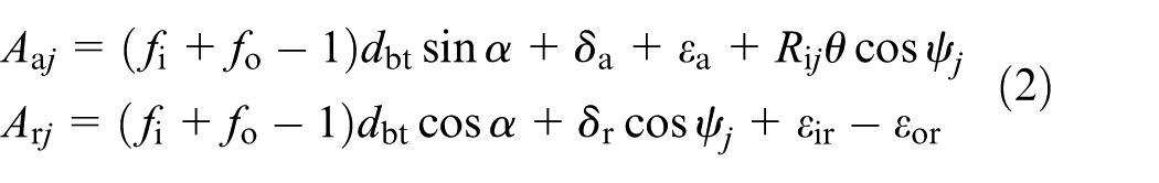
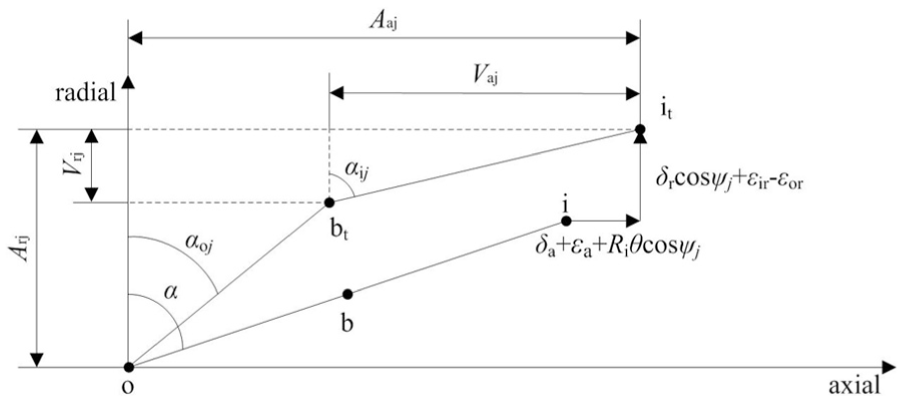
Compatible geometry relationship inside bearing.
Based on the compatible geometry relationship, the compatible equations can be obtained
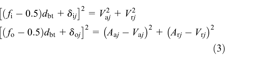
where fi and fo are the curvature coefficients of the radius of inner and outer ring, respectively; δij and δoj are the contact deformations between ball j and inner and outer rings, respectively.
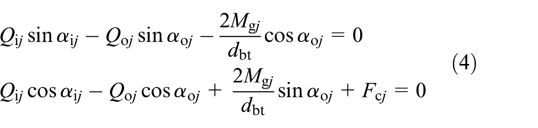
For ball j, centrifugal force Fcj, gyroscopic moment Mgj; and contact stresses Qij and Qoj with inner and outer groove together form a balanced force system, respectively 12
The load on the bearing from the outside should be equal to the contact load on the inner ring 12

where Fa, Fr, and M are the outside axial, radial, and angular loads on the bearing. Equation (5) can be expressed by vector form

where
Thermal model
The thermal model includes the heat generation models of bearing and built-in motor and the determination of heat boundary conditions.
Heat generation of bearing
With the bearing dynamic parameters obtained from the bearing model, the bearing heat generation is determined by Jorgensen’s 10 formula.
Heat generation of built-in motor
For three-phase AC induction motor, the power loss of motor consists of the copper loss and iron loss. The input power of the motor is

where U1, I1, and cosφ1 are the phase voltage, current, and power factor of the stator, respectively. The copper and iron losses of the stator are

where r1 is the resistance of stator winding; Im and rm are excitation current and resistance, respectively.
When a high-speed motorized spindle is running normally, the motor slip s is little enough to be neglected, and the copper and iron losses of the rotor are

where I2 and r2 are the rotor current and resistance, respectively; Pm is the electromagnetic power and Pm = P1 − PCu1 − PFe1.
Heat boundary conditions
Heat boundary conditions present the heat transfers inside the system and between the internal space and the external space of the system, which mainly include the heat convection inside the bearing; the air gap heat exchange between stator and rotor; the heat convection between cooling medium and stator; and heat dissipation at rotor, spindle end, and moving outer surface of spindle. 12
Spindle model
Based on the finite element theory and Timoshenko beam theory, the dynamic model of the system can be established. Considering the high-speed inertial effect and the bearing support stiffness with the thermal displacements, the kinematic equation of the spindle system is written as

where
Analysis
The article performed the example calculation on four series bearings and a D62D24A-type motorized spindle. The types of the bearings are 7004C/P4A, 7003C/P4A, 7002C/P4A, and 7001C/P1A, respectively, and the parameters of the motorized spindle are listed in Table 1.
Parameters of motorized spindle.

Bearing characteristics
According to Figure 3, the influence of the radial thermal displacements of bearing on the bearing characteristics depends on the difference between the expansions of the inner and outer rings, which is expressed as εir − εor. Figure 4 shows the influence of εir − εor on the bearing stiffness when the rotational speed is 36,000 r/min and the preload displacement is 5 μm. For the bearing with lock-ring preload, the relative position of the inner and outer rings is fixed, so the contact forces between the balls and inner and outer rings increase with the value of εir − εor, which improves the bearing stiffness.
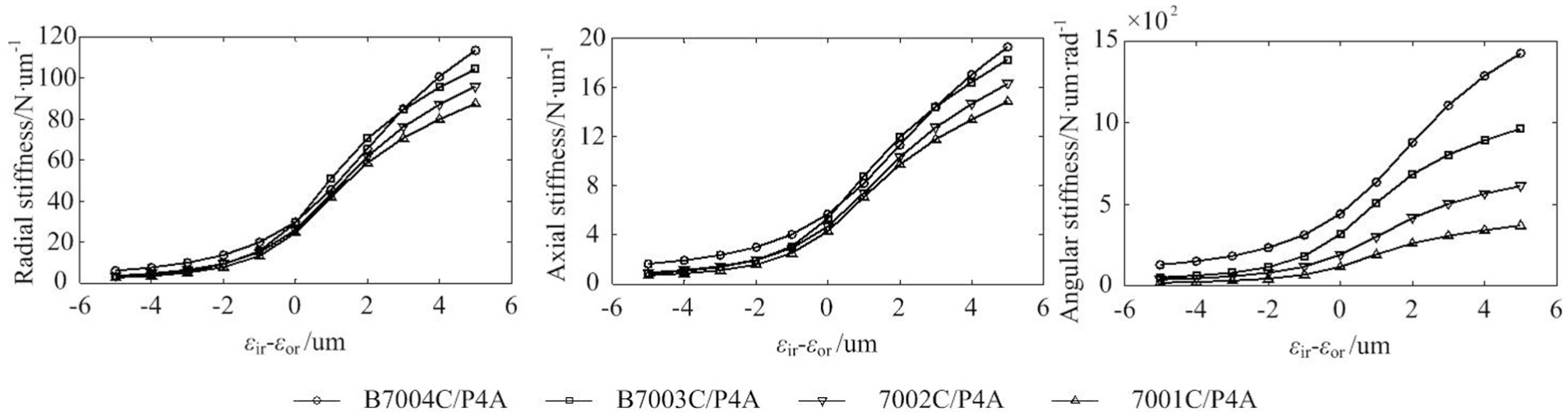
Influences of εir–εor on bearing stiffness.
Figure 5 shows the influence of εb on the bearing stiffness when the rotational speed is 36,000 r/min and the preload displacement is 5 μm. Without the influence of εir − εor, the bearing stiffness slightly increases with the value of εb; therefore, the ball thermal expansion has little influence on the bearing characteristics.

Influences of εb on bearing stiffness.
Figure 6 presents the influence of εh − εs on the bearing stiffness when the rotational speed is 36,000 r/min and the preload displacement is 10 μm without the influence of radial thermal displacements. The difference between the axial expansion of the housing and spindle affects the bearing stiffness by changing the sum of the preload displacements of the front and rear bearings, and the bearing stiffness increases with the value of εh − εs.

Influences of εh–εs on bearing stiffness.
Thermal characteristics
The electromagnetic power loss of the system is shown as Figure 7. Due to the U/f control method on the built-in motor, the stator, rotor, and excitation currents and the excitation resistance are directly proportional to the excitation frequency, so the values of PCu1, PFe1, PCu2, and Pm increase with the excitation frequency too. For an asynchronism motor, the increase in the s means the increase in the outside torque and the output power of the motor, so the values of I1, I2, PCu1, and PCu2 increase accordingly. Meanwhile, the value of Im slightly decreases with the value of s, so the value of Im decreases with a small range. Because the values of I1 and I2 are small, the copper loss is about equal to the iron loss at low excitation frequency; the copper loss plays a dominant role at high excitation frequency because the values of I1 and I2 increase.

The electromagnetic power loss of motor.
The structure of motorized spindle can be regarded as axis symmetry, so the thermal finite element model of the system is established with the element of axis symmetry. In the simulation, the rotational speed is 12,000 r/min; the cooling water flow rate is 1.0 L/min; the initial temperature is 25°C; s is 0.005; and the initial preload displacement is 10 μm. The contact resistance can be neglected when the temperature rise of the system is not high, and the temperature field distribution of the system is shown as Figure 8. It is known that the temperature rise is more severe near the heat source parts like the front and rear bearings and the motor, while the temperature rise of the stator is lower than other heat source parts due to the action of cooling water.

Temperature rise of motorized spindle system.
The motor slip s affects the temperature rise of the system by changing the power losses of the stator and rotor, and Figure 9 shows the temperature rises of the inner and outer rings and the ball without the influence of thermal displacements. With the increase in the value of s, the temperature rises of the bearings increase slightly, and the maximum increment is about 0.5°C. This is because the influence of s on the power loss of the motor is not great and the bearing is far away from the motor relatively. The temperature rise of the inner ring is higher than that of the outer ring and ball.

Influence of s on the temperature rises of bearings.
The influence of s on the temperature rise distributions of spindle and housing is presented as Figure 10. The power losses of the stator and rotor increase with the value of s, so the temperatures of spindle and housing increasing accordingly. The temperature distribution curve of spindle shows basin shape when s is low, which turns to cover shape with the increase in the s. Due to the action of cooling water, the temperature distribution curve of housing keeps basin shape, and the temperature is lower than that of the spindle.
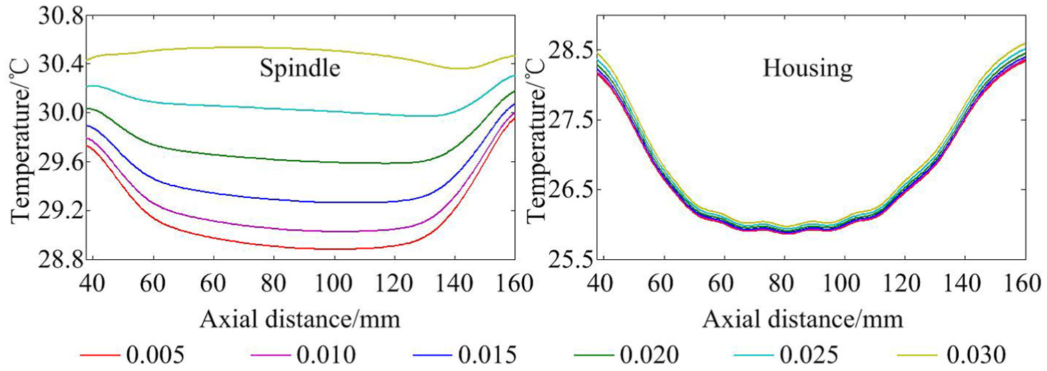
Influence of s on the axial temperature distribution of shaft and housing.
Dynamic characteristics of spindle system
The dynamic finite element model of the spindle system is established based on the structural characteristics of the system. The degrees of freedom of the bearings are absolutely coupled with that of the housing due to the lock-ring preload. The dynamic model is shown as Figure 11. When the housing is free, the model contains 27 nodes and 22 elements, and the connection between the spindle and housing is rigid. When the housing is fixed, the degrees of freedom of the housing are all restricted and the bearings can be regarded as directly connected to the fixed plane, and the numbers of nodes and elements of the model here are 16 and 15, respectively.

Dynamic finite element model of system.
Figure 12 presents the first natural modal shapes of the system. When the housing is free, the radial natural modal shapes show that the relative vibration amplitude of the housing is little and the maximum relative vibration amplitude of the spindle occurs at the middle part, and the axial natural modal shapes are the vibration of a rigid spindle; when the housing is fixed, the natural modal shapes are basically unchanged except the radial relative vibration amplitude is larger. Therefore, the first natural modal shapes of the system mainly happen at the spindle if the housing is free or fixed.

The first natural modal shapes of the system.
When the housing is free, the natural characteristics of the system are only influenced by the initial preload state, and the first natural frequencies are shown as Figure 13. The first natural shape of the system shows the whirling motion at the middle part of the spindle, and the bearing is not enough to support the system when the preload is little, so the first radial and axial natural frequencies increase with the initial preload displacement.

The first natural frequencies of the system.
Test
Based on the analysis above, the dynamic test on the D62D24A-type motorized spindle is carried out, and Figure 14 shows the experimental setup. In Figure 14(a), the acceleration sensors (PCB 356A32) and the hammer (CL-YD-303) are used to obtain the model parameters of the system, and the charge amplifier (YE5850) deals with the collected signals; in Figure 14(b), the temperature thermometric indicators (TES-1310) are utilized to measure the temperatures of key parts of system; the displacement sensor (WD501) and the charge amplifier (B&K2692-014) are used to deal with the vibration characteristics of the spindle after the temperature rise is stable. Figure 14(c) shows the spot test.

Experimental setup: (a) free model, (b) thermal and mechanical test, and (c) spot test.
Figure 15 presents the transfer and related functions of the system. It shows that the peaks of the transfer functions appear at the natural frequency, and the first free radial and axial natural frequencies of the system are 1264.1 and 978.2 Hz, respectively. Table 2 shows the modal damping ratios of the system, and the data are used to modify the dynamic model of the system. The intervals of low-frequency spectrums of related coefficients of the three test points, which are influenced greatly by noise, are far less than 1 while the first free natural characteristics of system present at the interval of high-frequency spectrums. Therefore, the noise has no influence on test results.
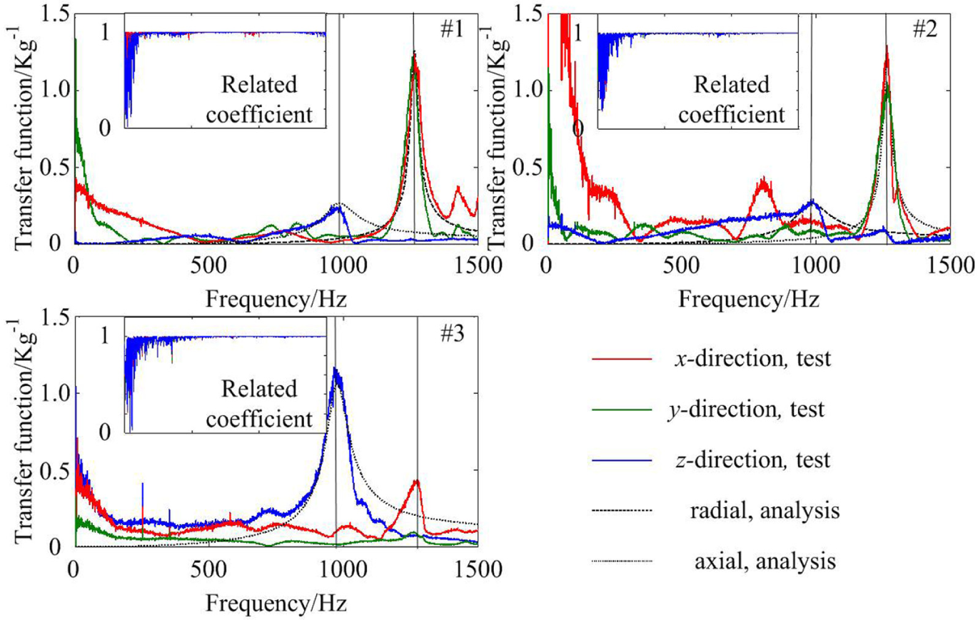
Transfer and related functions of the system.
Test modal damping ratios.

Figure 16 shows the temperature results of the three test points under different work conditions. The temperatures increase with the rotational speed. Meanwhile, the results decrease and have higher accuracy when considering the coupled factor (CF). Due to the action of cooling water and far distance from the bearings, the temperature rises at point 3 are lowest.

Temperature results of the system.
Figure 17 presents the vibration displacement signals and their frequency spectrums at the front end of the spindle (&2, the measurement point in mechanical and thermal test, which can be seen in Figure 14(b) and (c2)) with different excitation frequencies, and the first radial natural frequencies are 1305, 1260.6, and 1198.6 Hz, respectively. Combined with the results shown in Figure 18, it is known that the first natural frequency deceases with the rotational speed due to the soft action 21 on the bearing. The results with CF have lower values and higher accuracy compared with those without CF.
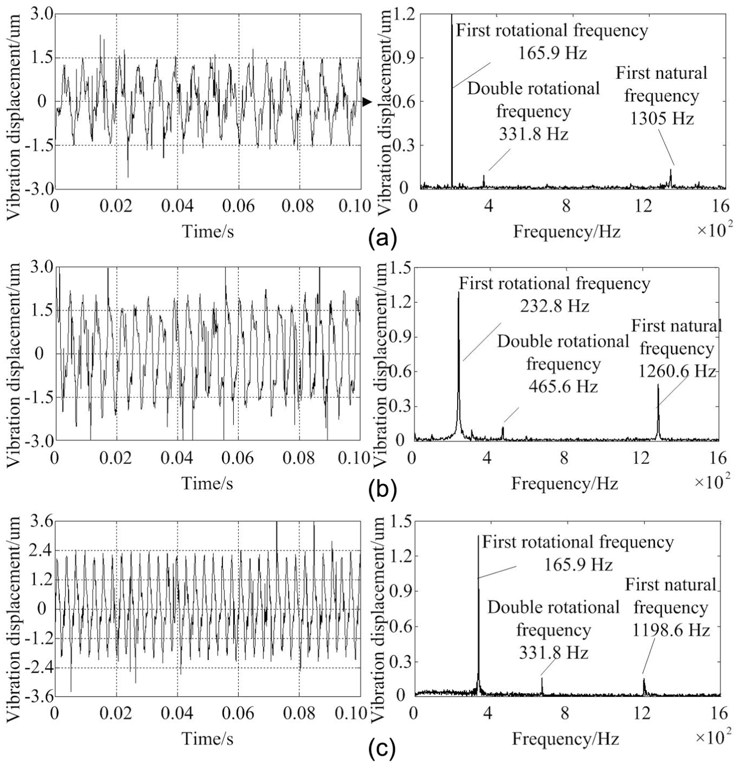
Temperature results of the system: (a) 166.7 Hz, (b) 233.3 Hz, and (c) 333.3 Hz.

The first radial natural frequency of the system.
Conclusion
An integrated dynamic model is developed and validated experimentally to discuss the thermo-mechanical coupling dynamic behaviors of motorized spindles. From the theoretical and experimental results, the following conclusions are drawn:
For lock-ring preload method, the bearing stiffness increases with the values of εir − εor and εh − εs, while the influence of εb on the characteristics can be ignored.
The electromagnetic power loss of the built-in motor increases with the value of s, and the temperature rises at key parts of the system accordingly except the middle part of housing due to the action of cooling water.
The first natural modal shapes of the system mainly depend on the spindle with free or fixed housing; the first natural frequency of the system increases with initial preload displacement when the housing is free.
Taking into account the CF, the temperature rises and first natural frequencies of the system increase, and the accuracy of the model improves.
Footnotes
Handling Editor: Francesco Massi
Declaration of conflicting interests
The author(s) declared no potential conflicts of interest with respect to the research, authorship, and/or publication of this article.
Funding
The author(s) disclosed receipt of the following financial support for the research, authorship, and/or publication of this article: This work was supported by the National Natural Science Foundation of China (No. 51405151).