
Abstract
One of the challenging problems in the forest industry is to develop a chassis that is well-adapted to the complex terrain conditions in the forest. In this article, a novel forestry chassis with an articulated body with 3 degrees of freedom and installed luffing wheel-legs (FC-3DOF&LW) is proposed, and the mechanical model of the luffing wheel-leg is built. Based on the mechanical model, the hydraulic cylinder velocity that involves the wheel-leg luffing is calculated. The process of surmounting the obstacle is presented by multi-body dynamics simulation. To demonstrate the improvement of ride comfort, the other simulation of the chassis with an articulated body with 3 degrees of freedom (FC-3DOF) is contrasted in multi-dynamics software. The final result shows that curves of barycenter displacement for FC-3DOF&LW with the front and rear frames are well matched when the front frame surmounts the obstacle; in particular, the barycenter displacement is almost stable when the rear frame surmounts the obstacle. The maximum rotated angle of the articulated joint reaches almost 37° without the luffing wheel-leg, whereas it is only 4° with FC-3DOF&LW, a decrease of 89.1%. Moreover, the acceleration trend for FC-3DOF&LW is more stable than that for FC-3DOF.
Introduction
Approximately half of the earth’s surface is inaccessible to conventional wheeled vehicles. Forestry vehicles in particular must move on the rough terrains of a forest, which makes it necessary to develop a special chassis that allows vehicles to drive into these forests for work.1–3 Poor quality roads in forests are the biggest challenges for off-road vehicles. However, the development of the off-road vehicle has received increasing interest and has been widely pursued by researchers.4–6
In general, forestry vehicles are based on the following two types of chassis: tracked or wheeled. 7 G Bygdén et al. 8 studied rolling resistance for bogie tracks on forestry machines and compared the effects of wheels and two types of bogie tracks on rut formation, cone index, and vehicle rolling resistance on some typical forest soils in Sweden. A detailed multi-body model for the dynamic simulation of off-road tracked vehicles was proposed by D Rubinstein and R Hitron 9 and developed using the LMS-DADS simulation program. A new design for a tracked forestry machine bogie (long track bogie (LTB)) on soft and rough terrain was investigated using non-smooth multi-body dynamics simulation by J Edlund et al.; 10 the new bogie was shown to have higher mobility. In addition, special types of tracked chassis were also researched. Conventional tracked vehicles have superior cross-country capability compared to common wheeled vehicles, but they also have poor maneuverability, especially poor steering performance, so a tracked omnidirectional vehicle was designed by YN Zhang and T Huang. The vehicle demonstrated omnidirectional motion on uneven terrains, superior steering efficiency, equal longitudinal motion efficiency, and comparable cross-country performance in comparison to conventional tracked vehicles. 11 It is difficult for ordinary vehicles to drive on a flat road and surmount obstacles that are longer than the size of wheel radius, such as stairways, so a study of machine design for a transformable shape single-tracked vehicle system was presented by J Kim et al. Utilization of a variety of shapes provided enhanced ability to surmount stair-like obstacles. 12 However, vehicles with tracked chassis cause significant damage to the soil and surrounding plants in the forests. 3
Aside from the studies of the tracked chassis, some methods have been adopted in the field to improve the performance of wheeled chassis by developing a key body structure.13–15 Bogies are common mechanisms that are applied in vehicles to ensure the even contact of the wheels on uneven terrain. A study performed by J Pijuan et al. 16 and M Comellas et al. 17 quantified the ability of overcoming obstacles using different configurations of vehicle with bogies. Bogies are robust, but their main drawback is their heavy weight. In addition, bogies combined with articulated steering create severe shearing of the soil when turning. 3 The structure of wheel-leg is usually applied, and a chassis taking a wheel-leg is similar to a robot. A luffing wheel-legged robot with six legs was introduced by ZB Sun and JH Liu. 18 This robot comprised mobile equipment and was designed to surmount obstacles actively on forest roads. However, the complexity of construction and control, given the coordinated simultaneous wheel-leg movement for the advancement of the vehicle, quickly led to problems such as low efficiency for surmounting obstacles. There are also numerous papers in the literature studying the structure of wheels to enhance the capacity of crossing obstacles. An innovative all-terrain vehicle with diameter-variable wheels was designed by XJ Yao et al. 19 Diameter-variable wheels have an advantage in that they could vary their diameter and overcome higher obstacles compared to standard wheels when enough traction is provided. The diameter of the wheels is varied by a driving motor installed inside the wheel. However, the complicated wheel structure is associated with some risks. Considering that some vehicles needed to drive on unstructured terrain, such as stairs. GY Ge and YJ Wang 20 proposed a model of a quadruped eccentric wheel chassis, which achieved excellent performance when crossing obstacles, even exhibiting the ability to climb stairs. Although the chassis-installed quadruple eccentric wheel enhances the trafficability, vehicle ride comfort is sacrificed. Meanwhile, the low speed of the chassis, which was caused by installing quadruped eccentric wheel-leg, had an effect on driving efficiency on flat roads. Articulated chassis have the characteristic of a small radius of steering and are suitable for working in narrow spaces. This advantage is applied in designing a chassis to work in forests. A study that analyzed the obstacle-surpassing ability of a forestry chassis with an articulated body with 3 degrees of freedom (FC-3DOF) was presented by Y Zhu and JM Kan. 21 Due to poor adaptability to terrain and lack of adhesive force, conventional forestry machinery chassis is prone to wheel-slippage when they work in hilly areas. To address these problems, a six-wheel-driven articulated chassis adopting the principle of adapting to terrain was designed with 3 degrees of freedom. The obstacle-crossing performance of the FC-3DOF was analyzed through curves of barycenter displacements for frames and the force between wheels and ground by multi-body dynamics software, and the simulation results showed that the FC-3DOF had good adaptability to the terrain, good trafficability, and flexible steering ability compared with conventional six-wheeled chassis. The FC-3DOF adapted to terrain and provided contact between wheels and ground at all times, which contributed to successful driving in rough terrain. However, poor ride comfort was present when crossing obstacles. The variation in barycenter displacement for the rear frame is especially obvious in the vertical direction, and a phenomenon that affects front frame and rear frame occurs. In addition, the large acceleration in the vertical direction negatively affected its ability to surmount the obstacle safely and also led to damage of component parts. Based on the issues above, a novel wheel-legged structure with active control was installed in the rear frame. As a result, curves of barycenter displacement with cooperation between the articulated body and novel wheel-leg are well matched while crossing the obstacle, and the maximum rotation angle of the articulated joint decreases by 89.1%. Moreover, the trend of acceleration is also more stable than that in FC-3DOF. Thus, the increased ride comfort of FC-3DOF&LW is achieved.
Structure of the FC-3DOF&LW
Introduction of the FC-3DOF&LW
FC-3DOF&LW is proposed to traverse rough terrain in the forest. As shown in Figure 1, the presented FC-3DOF&LW is a combination of two frames, two front wheels, and four rear wheel-legs. The two frames are connected by an articulated structure with 3 degrees of freedom. Importantly, the four rear wheel-legs with a luffing function are attached to the rear frame and distributed on both sides symmetrically, each with a wheel in the end. FC-3DOF&LW is an improved chassis with installed luffing wheel-legs in the rear frame based on an original FC-3DOF. 21 This aims to ensure good contact between the wheels and road and enhance ride comfort on uneven terrain in the forest.

Structure of the FC-3DOF&LW.
Luffing wheel-leg
This luffing wheel-leg is an active piece of equipment that is operated by lifting hydraulic cylinder 3 and dropping hydraulic cylinder 6. As shown in Figure 2, the wheel-leg will lift when lifting hydraulic cylinder 3 shortens and will drop when dropping hydraulic cylinder 6 elongates. To reduce control complexity, lifting hydraulic cylinder 3 and dropping hydraulic cylinder 6 are self-moving, with uncoupled motion. The luffing wheel-leg is firmly installed in rear frame through joint structure 4, that is, fixed joint with fixed structure 2. A simulation that involves mechanical intension of luffing wheel-leg is finished in ANSYS workbench. The result shows that luffing wheel-leg is strong enough to run in rough terrain. In addition, the active luffing wheel-leg could match with articulated body with 3 degrees of freedom, which ensures good contact between the wheels and road and furthermore improves the ride comfort on uneven terrain in the forest.

Structure of the luffing wheel-leg.
Mechanical model of the luffingwheel-leg
Kinematics of the luffing wheel-leg
To represent the basic geometric aspects of the luffing wheel-leg, it is necessary to develop a kinematics analysis. Here, according to the structure of the luffing wheel-leg, a simplified model is shown in Figures 3 and 4, and the related parameters are shown in Table 1.

Sketch of luffing wheel-leg with lifting.

Sketch of luffing wheel-leg with dropping.
Initial parameters of the luffing wheel-leg.

As shown in Figure 3, the rotary structure 5 has a rotation of

In addition,


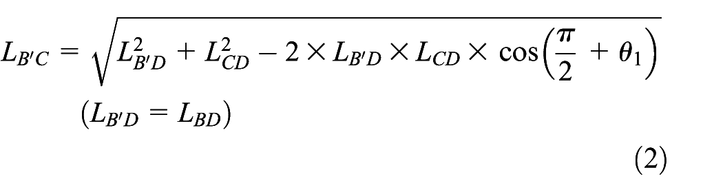
The equation above yields the following result


The other condition of the luffing wheel-leg with a downward motion is described in Figure 4. It is different from upward motion. In contrast, the length of the lifting hydraulic cylinder 3 is not changed, and the dropping hydraulic cylinder 6 elongates gradually. The displacement of point


The equation above yields the following result

A Jacobian matrix is calculated to establish the kinematics model. As the lifting and dropping of the wheel-leg are uncoupled motion, the movements must be considered separately. A shortened hydraulic cylinder 3 leads to lift for the wheel-leg. The matrix between the angular velocity of


where


The matrix of the dropping of the wheel-leg, which is caused by the elongation of hydraulic cylinder 6, is similar to the above
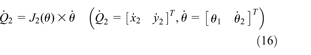

Then, based on equations (1) and (9), a relationship between the angular velocity of


Based on equations (12)–(19) above, the kinematics of the luffing wheel-leg are separately presented in the following:
1. The luffing wheel-leg is lifting


where
2. The luffing wheel-leg is dropping


where
Dynamics of the luffing wheel-leg
The dynamic approach in this work is based on the Euler-Lagrange method, which describes the motion of a mechanical structure with holonomic constraints. As a function of the generalized coordinates, the Lagrangian L of the system can be defined as follows

where
The Lagrange equation is written in the following form

where
The total kinetic energy of the system is written in the following form

where
For simplicity, it is assumed that the tire is elastic and that the road is a rigid body. The vehicle is driving at a constant speed, and variation of the rear frame is slight. Hence, based on the relationship of wheel-leg movement,

where
The potential energy increases only due to gravitational forces. The value of the potential energy is associated with the position of the coordinate system. Point “O” is the origin of coordinates (shown in Figures 3 or 4), and friction is neglected with the movement of the wheel-leg. The potential energy of the system can be written as follows


where

where
As a result, the dynamics of the luffing wheel-leg are built in the following

where

Simulation experiments and results analysis
Establishment of the simulation
The virtual prototype of FC-3DOF&LW is established in SolidWorks and is imported into ADAMS that is applied in multi-body dynamics simulation. The initial velocity of the FC-3DOF&LW is 2 m/s, and the basic parameters are shown in Table 2. Tires of chassis are based on Fiala model, and parameters are shown in Table 3. In addition, a 100-mm-tall obstacle is built in ADAMS and height of obstacle is selected randomly.
Basic parameters of the FC-3DOF & LW in simulation.

Parameters of tires.

According to the relative size, the time needed to cross the obstacle is approximately 12.5 s. Herein, the simulation time is 15 s, and the number of steps is 2000. Especially, to surmount the obstacle for the rear frame, the rear frame wheel-legs must lift, so the movement of lifting hydraulic cylinders is divided into two parts: one is the lifting for the two wheel-legs in the front of the rear frame and the other is the lifting for the rear of the rear frame. Based on the kinematics equations (20) and (22) of the luffing wheel-leg, the velocity functions of the lifting hydraulic cylinders and dropping hydraulic cylinders are matched by MATLAB in the following.
The velocity functions of the two lifting hydraulic cylinders in the front of the rear frame
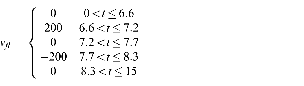
The velocity functions of the two lifting hydraulic cylinders in the rear of the rear frame
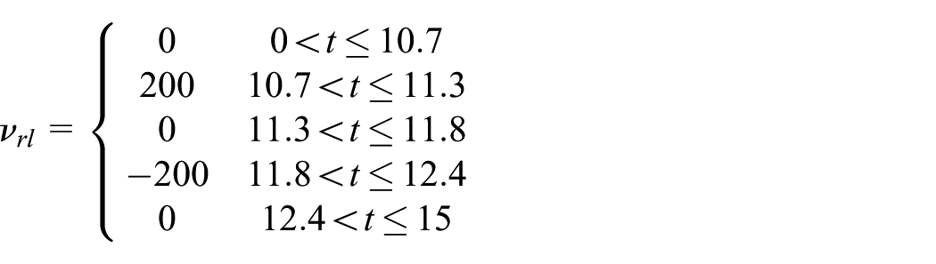
The velocity functions of the four dropping hydraulic cylinders
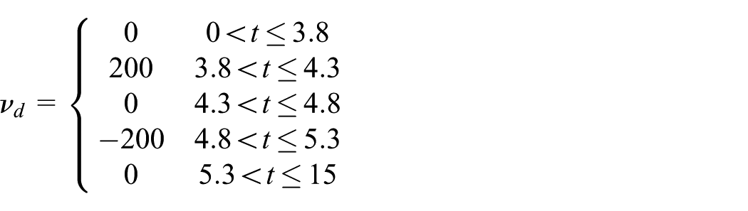
In the ADAMS environment, a simulation of surmounting the obstacle of the FC-3DOF&LW is conducted, and it is compared with a FC-3DOF, as shown in Figure 5.

The comparison between FC-3DOF&LW and FC-3DOF in surmounting the obstacle in ADAMS: (a) comparison of surmounting the obstacle with the front wheels, (b) comparison of surmounting the obstacle with the front wheels of the rear frame, and (c) comparison of surmounting the obstacle with the rear wheels of the rear frame.
The comparison between FC-3DOF&LW and FC-3DOF in the process of surmounting the obstacle can be seen in ADAMS. For FC-3DOF&LW, the dropping hydraulic cylinders are helpful to surmount the obstacle with the front frame. Meanwhile, the lifting hydraulic cylinders play an important role in surmounting the obstacle with the rear frame. FC-3DOF&LW ensures good adaptability to the terrain and enhances ride comfort. However, FC-3DOF has poor ride comfort.
Analysis of the simulation results
The simulation results are divided into two groups, one with luffing wheel-legs and the other without luffing wheel-legs. Curves of barycenter displacement for the front and rear frames are shown in Figure 6. Figure 6(a) shows the simulation results when FC-3DOF surmounts the obstacle. Surmounting the obstacle by the front frame occurs at approximately 3.8–5.3 s and by the rear frame at approximately 7.5–11.5 s. The inconsistent trend of the two curves demonstrates the poor ride comfort, specifically between the front frame and the rear frame during 10.1–11.5 s. The variation of barycenter displacement for the front frame is especially obvious when the rear frame surmounts the obstacle. However, for FC-3DOF&LW, as seen in Figure 6(b), the front frame still surmounts the obstacle at approximately 3.8–5.3 s; meanwhile, the luffing wheel-legs that are installed in the rear frame start to operate from 3.8 to 5.3 s. Curves of barycenter displacement between the front and rear frames are well matched, indicating that they provide a smooth drive for crossing the obstacle. In addition, the luffing wheel-legs are working when the rear frame of the chassis starts to surmount the obstacle from 6.6 to 12.4 s, which ensures a small barycenter variation in the vertical direction.

Curves of barycenter displacement for (a) FC-3DOF and (b) FC-3DOF&LW.
Figure 7 contrasts the angle variation of the articulated joint (shown in Figure 8) between FC-3DOF and FC-3DOF&LW. Based on curves, the maximum angle reaches almost 37° for the FC-3DOF but is only 4° for FC-3DOF&LW. In terms of maximum angle, we could obtain the percent decrease in angle variation using the formula (Max1 − Max2)/(Max1) × 100%, and the value is 89.1%. This means that the process of crossing the obstacle involves less pitching motion and is smoother for the FC-3DOF&LW.

The rotation angle of the articulated joint.

Schematic diagram of the articulated joint.
The comparison of acceleration between FC-3DOF and FC-3DOF&LW is shown in Figure 9. The acceleration of the front frame in the vertical direction is more stable for FC-3DOF&LW than for FC-3DOF, as indicated in Figure 9(a). In addition, in terms of the rear frame shown in Figure 9(b), an obvious decrease in acceleration while crossing the obstacle is observed. However, the reason for the acceleration increases from 3.8 to 5.3 s is likely to be the luffing wheel-legs operation to match with the front frame while surmounting the obstacle. In addition, to ensure the simulation exactly, a 150-mm-tall obstacle is also tested in ADAMS, and the results show that FC-3DOF&LW is still smooth when surmounting the larger obstacle.
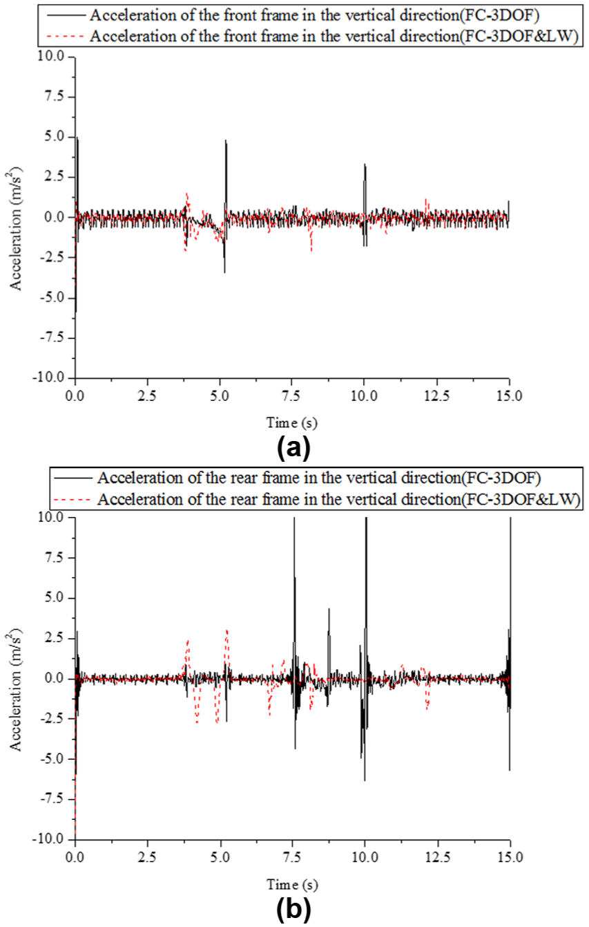
Curves of acceleration in the vertical direction: (a) the acceleration of the front frame in the vertical direction and (b) the acceleration of the rear frame in the vertical direction.
Based on the comparison above, FC-3DOF&LW is smoother when surmounting the obstacle than FC-3DOF. Meanwhile, FC-3DOF&LW also ensures good contact between the wheels and road, which contributes to a strong driving power.
Conclusion
A novel forestry chassis with an articulated body with 3 degrees of freedom and installed luffing wheel-legs (FC-3DOF&LW) was proposed, which had a good adaptability to the terrain and good trafficability. Ride comfort was especially enhanced by the installed luffing wheel-legs.
Kinematics of the luffing wheel-leg were built. Furthermore, dynamics based on the Euler-Lagrange method were also constructed. Based on kinematics and relevant parameters of the luffing wheel-leg, the velocities of lifting hydraulic cylinder 3 and dropping hydraulic cylinder 6 are acquired when FC-3DOF&LW surmounts the obstacle. All models were defined parametrically, so that they are suited for comprehensive design and optimization.
Comparisons of obstacle surmounting by FC-3DOF and FC-3DOF&LW are simulated with ADAMS. For FC-3DOF&LW, curves of barycenter displacement between the front and rear frames achieve good matching, and the maximum angle of the articulated joint decreases by 89.1%. Meanwhile, the acceleration in the vertical direction is also more stable than for FC-3DOF, which ensures that obstacles are crossed safely and is helpful in extending the service life of component parts. As a result, greater ride comfort is achieved by FC-3DOF&LW.
Footnotes
Handling Editor: Mario L Ferrari
Declaration of conflicting interests
The author(s) declared no potential conflicts of interest with respect to the research, authorship, and/or publication of this article.
Funding
The author(s) disclosed receipt of the following financial support for the research, authorship, and/or publication of this article: This work was supported by the Fundamental Research Funds for the Central Universities (Grant No. 2015ZCQ-GX-01) and Beijing municipal construction project special fund.