
Abstract
The chaos phenomenon often exists in the dynamics system of the mechanism with clearance and friction, which has obvious effect on the stability of the mechanism, then it is worthy of attention for identifying the relationship between the friction coefficient and the stability of the mechanism. Two rotational degrees of freedom decoupled parallel mechanism RU-RPR is taken as the research object. Considering the clearance existing in the revolute pair, Lankarani–Nikravesh contact force model is used to calculate the normal contact force, and the Coulomb friction force model is used to calculate the tangential contact force. The dynamics model is established using Newton–Euler equations, and the Baumgarte stabilization method is used to keep the stability of the numerical analysis. Then, the equations are solved using the fourth adaptive Runge–Kutta method, and the effect of the revolute pair’s clearance on the dynamic behavior is analyzed. Poincare mapping is plotted, and the bifurcation diagrams are analyzed with varying the friction coefficient corresponding to different values of clearance size. The research contents possess a certain theoretical guidance significance and practical application value on the analysis of the chaotic motion and its stability in the dynamics of the parallel mechanism.
Introduction
Due to the existence of the error in the process of design, manufacture, installation, and the friction and the wear, the kinematic pairs of the mechanism always produce clearance. 1 While the existence of the clearance will have great influence on the performance of the mechanism, 2 result in the shock vibration, reduce the work efficiency and the accuracy, 3 and even cause the failure of the mechanism.
In recent years, the establishment of dynamic model,4–6 the chaos phenomenon, 7 and the experiment analysis 8 of the mechanism with clearance were widely studied by many scholars. Flores et al. 9 studied on the dynamics of the clearance mechanism with lubrication. Bai and Zhao 6 proposed a hybrid contact force model based on the Lankarani–Nikravesh contact force model and the improved elastic model. Wang and Liu 10 established the dynamic model of the 4-SPS/CU (S stands for the spherical pair, P stands for the prismatic pair, C stands for the cylindrical pair, U stands for the hooke joint) parallel mechanism with spherical pair clearance using the augmented method, and analyzed the influence of clearance on the dynamic characteristics of the mechanism. Zhang et al. 11 took the planar 3-RRR parallel mechanism with multiple clearances as the research object, and analyzed the influence of different loads, velocities, and trajectories on the accuracy and stability of the mechanism.
Because the impact will cause vibration, the influence of the clearance on the stability of the mechanism cannot be ignored. Varedi et al. 12 set the minimum contact force as the optimization target and optimized the quality of the slider-crank mechanism with clearance to reduce the impact and vibration, and improve the stability of the mechanism. Based on ADAMS software, the stability of high speed and heavy load mechanism with clearance were analyzed and optimized by Zhang et al. 13 Olyaei and Ghazavi 14 changed the motion of the slider-crank mechanism with clearance from chaotic to periodic.
The clearance and friction have a significant influence on the stability of the mechanism, and the bifurcation diagram can be used to study the effects of the continuous variation of parameters on the stability of mechanism motion. The bifurcation diagram of the mechanism with varying clearance size was studied and the effect of the clearance on the stability of the mechanism was analyzed by Rahmanian and Ghazavi 7 and Tang et al. 15 Besides the clearance size, the friction coefficient has a certain effect on the stability of the mechanism, but it has not yet been reported as the study of bifurcation diagram of mechanism with varying friction coefficient.
Taking a rotational decoupled parallel mechanism RU-RPR (R stands for the revolute pair) as the research object, the dynamics equations are established and solved numerically, and the nonlinear phenomena of the chaos and bifurcation in the mechanism are studied. In addition, the influence of friction coefficient on the stability of mechanism motion is analyzed.
Dynamic modeling of the RU-RPR decoupled parallel mechanism with clearance
Figure 1 shows the structural composition of the RU-RPR decoupled parallel mechanism. It comprises a fixed base, a moving platform, and two limbs which connect the fixed base and the moving platform. In the second limb, the direction of the prismatic pair E is perpendicular to the axes of the two rotation pairs C and D. In the two limbs, the two axes of the rotation pairs A and D connected with the fixed base are parallel with each other and parallel to one of the axes of the hooke joint B, while another axis of the hooke joint is collinear with the axis of the revolute pair C. 16 The static coordinate system o0-x0y0z0 is attached to the fixed base, and the local coordinate system o2-x2y2z2 is attached to the moving platform. The local coordinate system oi-xiyizi (i = 1, 3, 4) is attached to the center of mass of the component i (i = 1, 3, 4), the original point oi (i = 1, 3, 4) is set at the center of mass of the component i (i = 1, 3, 4), and all coordinate origins are in the same plane.

Structure diagram of the RU-RPR rotational decoupled parallel mechanism.
Four moving components contained in the RU-RPR parallel mechanism, which are the link in the first limb, the moving platform, and two links in the second limb. In this article, it is assumed that the clearance exists in the revolute pair D, and the other joints are all in ideal state. To describe the kinematic of the mechanism, the generalized coordinates of the mechanism are selected as follows

where qi (i = 1, 2, 3, 4) are the mass center coordinates of the component i (i = 1, 2, 3, 4).
Due to the motion of components 1, 3, and 4 are all in the plane xioiyi (i = 1, 3, 4), in the static coordinate system, the components 1, 3, and 4 can be written as

where xi, yi are the components of the coordinates of the center of mass in the static coordinate system. θi is the rotation angle between the local coordinate system and the static coordinate system with respect to z0.
The moving platform of the mechanism has two rotational degrees of freedom which can rotate around z2-axis and y2-axis in sequence. If the rotation of the local coordinate system on the moving platform relative to the static coordinate system is represented by the Euler angle of z-y-x type, it can be written as (θ2β2 0)T, and the moving platform in the static coordinate system can be expressed as follows

The constraint equations in the joint points A, B, and C of RU-RPR parallel mechanism can be written as

where i and j are the components combined by the connecting joints;

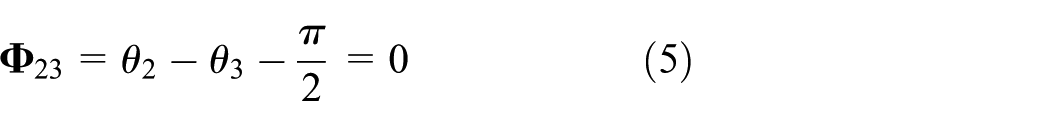
Considering components 2 and 3 are always perpendicular, the following equation can be obtained as
According to the geometrical relationship of the RU-RPR parallel mechanism, the movement direction of the prismatic pair E is perpendicular to the axis of the revolute pair C; therefore, o2C is perpendicular to o3o4. The direction of the vectors o2C and o3o4 is represented as


In addition, the two driving constraint equations are also established as


where
For the existence of the clearance in the revolute pair D, the kinematic constraints will be removed and the force constraints will be added instead. By equations (4)–(9), the ideal kinematic pairs and the driving constraint equations of the RU-RPR parallel mechanism with clearance are composed as follows
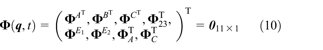
Solving the derivative of equation (10) with respect to time, the velocity constraint equation can be obtained as

where
Solving the second-order time derivative of equation (10), the velocity constraint equation can be obtained as

where
The dynamics equations with Lagrange multipliers are established using Newton–Euler method, which can be expressed as follows
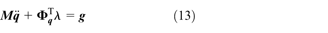
where
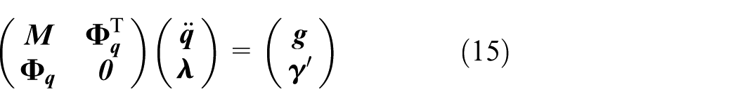
According to equations (12) and (13), a differential algebraic equation can be formed as follows

Then, the variables
At present, the most commonly used and effective method to deal this problem is the constraint violation stabilization method proposed by Baumgarte. 17 The method introduces the displacement and the velocity constraint into the acceleration constraint equations using the feedback control theory, which can be written as
where
Calculation of the contact force in the revolute pair with clearance of RU-RPR parallel mechanism
The clearance model of the revolute joint of RU-RPR parallel mechanism is shown in Figure 2. The center of the bearing and the shaft are denoted as


Rotation pair clearance diagram of RU-RPR parallel mechanism.
The unit vector of

where the magnitude of the clearance vector is evaluated as
The penetration depth during contact between the bearing and the shaft can be written as

where c is the clearance value, and c = Ri − Rj, and Ri and Rj are the radii of the bearing and the shaft, respectively.
When δ is positive, the bearing is in contact with the shaft. On the contrary, the bearing and the shaft are separated.
The collision force is inevitable in the collision process, and the Lankarani–Nikravesh 18 contact force model is used to calculate the normal contact force. The normal contact force Fn of the shaft to the bearing is shown as follows

where K is the stiffness coefficient related to the geometry of the contact surface and the physical property, Da is the damping coefficient in the process of collision, n is a constant between 1.0 and 1.5, and set to 1.5 here, and
The first item on the right-hand side of equation (19) represents the elastic deformation force during the collision process, which is obtained by Hertz contact formula. The second term represents the damping force during the collision process to consider the energy loss. The stiffness coefficient can be expressed as
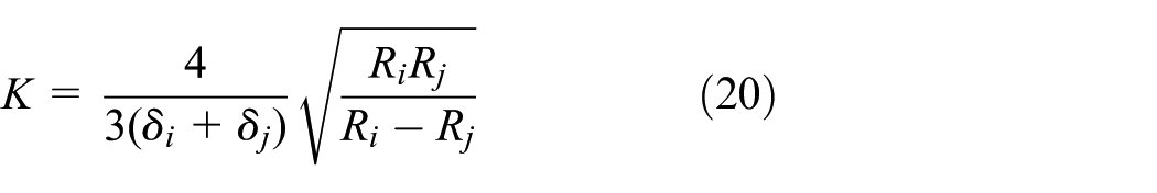
where
The damping coefficient is as follows

where
To obtain the tangential contact force, the modified Coulomb friction law proposed by Ambrósio 19 is used. This rule can prevent the tangential contact force from the mutation of direction, which is conducive to the stability of the numerical integration. The tangential contact force of the shaft to the bearing is as follows

where cf is the friction coefficient, cd is the dynamic correction coefficient, and vt is the relative tangential velocity of the collision.
The dynamic correction coefficient is given as follows
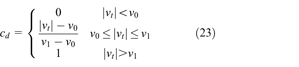
where v0 and v1 are the given tolerances of the tangential velocity.
The impact force of the shaft to the bearing can be expressed as follows

where fix and fiy are the components of impact force along X-direction and Y-direction, respectively.
Dynamic numerical simulation of RU-RPR parallel mechanism
Equations of motion which governed the system dynamics are derived in the previous section. The numerical integration of the differential equations must be performed in two different phases of contact and non-contact modes. In this sense, it is important to detect the precise instant of contact. The condition of the collision between the bearing and the shaft is as follows

Thus, the contact will occur between the two discrete times of tn and tn + 1. The collision time is very short, taking into account the computational efficiency and the accuracy of the calculation, the variable step-size fourth-order Runge–Kutta method 20 is used to carry out numerical integration.
If the collision penetration depth is beyond the integral error, the integral step is set to half of the previous step, and the calculation is redid until the error meets the requirements.
Considering to avoid the singular configuration, 21 the law of motion of RU-RPR parallel mechanism is set as follows

where
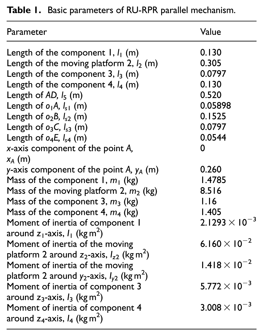
As shown in Figure 1, the shape of the components of RU-RPR mechanism is usually used as rectangular and cylindrical, the material is chosen to be 45 steel, and the relevant parameters can be obtained as shown in Table 1.
Basic parameters of RU-RPR parallel mechanism.
The dynamics simulation parameters of RU-RPR parallel mechanism are shown in Table 2. About the value of Baumgarte coefficients α and β, many groups of parameters were selected and calculated separately. Through comparing the results of calculation, the value of 50 is selected for Baumgarte coefficients α and β, and at this time, the result is more stable. In addition, the size of the clearance at D position is set to be 0.5 mm, the friction coefficient is taken as 0.01, and ω = 10π.
Dynamic simulation parameters of RU-RPR parallel mechanism.

The dynamics numerical solution process of RU-RPR mechanism is shown in Figure 3.
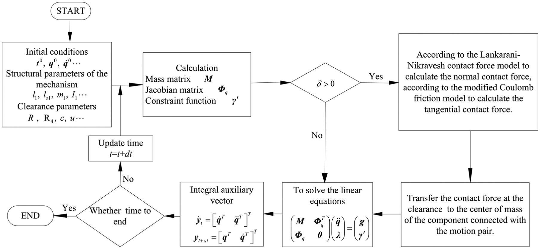
Dynamics numerical solution process of RU-RPR mechanism.
According to the flow chart, the MATLAB software is used to program and calculate, and the dynamic response of RU-RPR parallel mechanism with clearance is shown in Figure 4. The angular acceleration of the moving platform of the mechanism with clearance and no clearance is compared as shown in Figure 4(a). From 1.4 to 1.464 s, the angular acceleration curve is smooth, and the acceleration curve in Figure 4(b) is similar to that of the curve. Meanwhile, from Figure 4(d), it can be seen that the mechanism is in a continuous contact state, the penetration depth changes smoothly, and the contact force curve in Figure 4(e) is corresponding to that. By the way, the position is shown as zero in Figure 4(d), which is only used to represent the state of separation and related to the definition of penetration in equation (18). And there is no force transfer when separation, so the contact force value is also zero corresponding to that shown as zero in Figure 4(d).

Dynamic response of RU-RPR parallel mechanism with clearance: (a) Angular acceleration curve, (b) acceleration curve, (c) trajectory of the shaft center, (d) penetration depth curve, (e) contact force curve, (f) phase trajectory of relative velocity, (g) phase trajectory of relative displacement and relative velocity, and (h) phase trajectory of relative velocity and acceleration.
From 1.673 to 1.712 s, the angular acceleration curve and the acceleration curve fluctuate violently with a lot of peaks. At the moment the penetration depth fluctuates sharply in Figure 4(d), the shaft and the bearing transform between the contact state and the separation state rapidly. The trajectory of the shaft center relative to the bearing center also exists in the states of separation and collision in Figure 4(c) (where the dotted circle indicates the boundary of the bearing, its center is at the center of the bearing, and its radius is the radius of bearing), and the corresponding contact force curve also fluctuates violently. This is because the penetration depth influences the contact force directly and the contact force, which has great influence on the dynamic characteristics of the mechanism, can transmit to each component. Therefore, if the shaft and the bearing with clearance form continuous contact which makes the penetration depth fluctuate slightly, then the impact can be suppressed effectively.
In addition, Figure 4(f) represents the phase trajectory between the relative velocity along x-direction and that along y-direction in the clearance of the rotation pair. Figure 4(g) represents the phase trajectory between the relative displacement and the relative velocity along x-direction. Figure 4(h) represents the phase trajectory between the velocity and acceleration at the center of the moving platform. These phase trajectories exhibit non-periodicity, which indicate that the motion of the mechanism is nonlinear due to the existence of clearance.
Chaos phenomenon analysis of RU-RPR parallel mechanism
Bifurcation diagram with the change of the friction coefficient
Since the bifurcation diagram can show the influence of the continuous change parameters on the stability of the mechanism, the bifurcation diagrams with the change of friction coefficient are drawn as follows.
According to the parameters listed in Tables 1 and 2, and setting ω = 10 π, the clearance is set as 0.05 and 0.5 mm, respectively. Meanwhile, the variation range of the friction coefficient is [0.01, 0.2], then the dynamic equations of RU-RPR parallel mechanism can be solved. And 30 mapping points corresponding to each friction coefficient are taken to plot the bifurcation diagram.
Figure 5 shows the bifurcation diagram of RU-RPR parallel mechanism with clearance, in which x-axis and y-axis represent the friction coefficient and the relative speed of the clearance along x-direction, respectively. As shown in Figure 5(a), when the friction coefficient is in [0.12, 0.2], the mechanism is in periodic motion. As shown in Figure 5(b), when the friction coefficient is in [0.14, 0.152], the mechanism is in the periodic motion and reaches a steady state. Comparing Figure 5(a) and (b), it can be found that the mechanism is more stable when the clearance of the revolute pair is smaller. On the whole, the change of the friction coefficient has great influence on the movement of the mechanism, and the mechanism will be more stable with the increase in the friction coefficient.

Bifurcation diagram of RU-RPR mechanism with the change of friction coefficient: (a) ω = 10 π, c = 0.05 mm and (b) ω = 10 π, c = 0.5 mm.
Poincare mapping with different friction coefficients
It is different for Poincare mapping from the phase trajectory, an appropriate cross section in multi-dimensional phase space
According to the parameters listed in Tables 1 and 2, and setting ω = 20 π, the size of the clearance is set to be 0.5 mm, the friction coefficient is taken as 0.01, 0.02, and 0.05, then the Poincare mappings of RU-RPR mechanism are shown in Figures 6–8, respectively. The x-axis and y-axis represent the relative velocity along x- and y-directions in the rotation pair clearance in Figure 6(a), respectively. In Figure 6(b), the x-axis and y-axis represent the relative displacement along x- and y-directions in the rotation pair clearance, respectively. In Figure 6(c), the x-axis and y-axis represent the relative displacement and the relative velocity along x-direction in the rotation pair clearance, respectively. In Figure 6(d), the x-axis and y-axis represent the relative displacement and the relative velocity along y-direction in the rotation pair clearance, respectively. The physical meaning of the coordinate axes in Figures 7 and 8 is the same as in Figure 6.
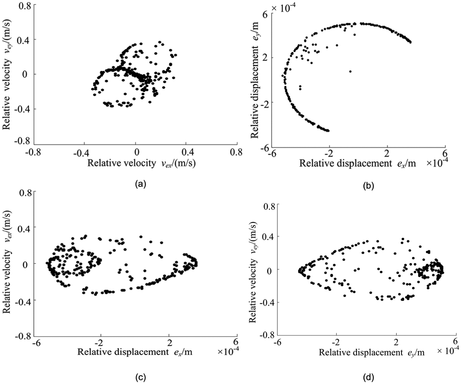
Poincare mapping with friction coefficient of 0.01: (a) relative velocity, (b) relative displacement, (c) relative displacement and relative velocity of x-direction, and (d) relative displacement and velocity of Y-direction.
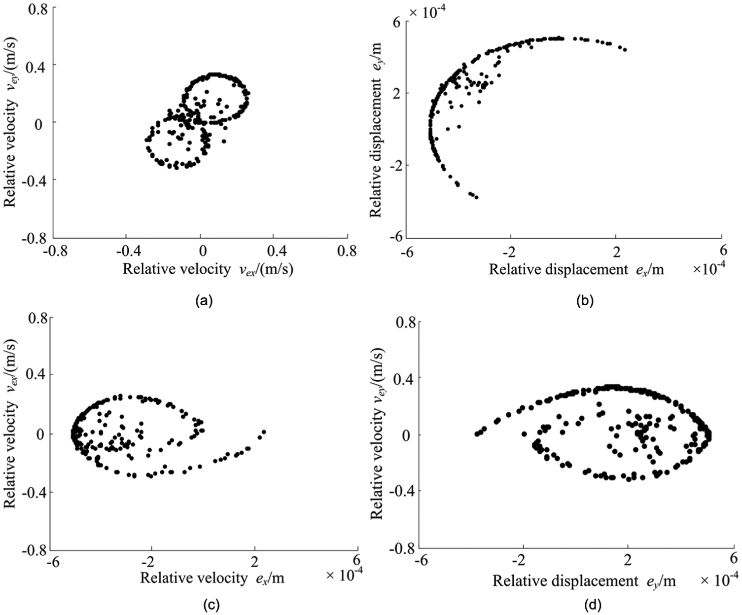
Poincare mapping with friction coefficient of 0.02: (a) relative velocity, (b) relative displacement, (c) relative displacement and relative velocity of x-direction, and (d) relative displacement and velocity of Y-direction.

Poincare mapping with friction coefficient of 0.05: (a) relative velocity, (b) relative displacement, (c) relative displacement and relative velocity of x-direction, and (d) relative displacement and velocity of Y-direction.
As shown in Figure 6, lots of mapping points present a fractal structure and not the isolated point or closed curve, so it can be judged that RU-RPR parallel mechanism is in a chaotic state at this moment. Similarly, the mechanism in Figure 7 is in a chaotic state as well, and compared to Figure 6, the map of the Poincare mapping has a tendency to shrink. However, the mechanism is in a periodic motion obviously in Figure 8.
Comparing Figures 6–8, it can be seen that under the present conditions, with the increase in the friction coefficient, the mechanism changes from the chaos to the periodic motion, which means the mechanism becomes more stable.
Conclusion
The Lankarani–Nikravesh contact force model, a modified Coulomb friction law, and Newton Euler method were used to establish the dynamic model of RU-RPR decoupled parallel mechanism with clearance, and the stability of the numerical calculation was guaranteed using the Baumgarte stability algorithm, which has reference significance for the modeling of spatial parallel mechanism.
The fourth-order Runge–Kutta method with varying step size was used for the numerical solution of the dynamic equations, and the dynamic simulation results of RU-RPR parallel mechanism with clearance indicated that the clearance has great influence on the dynamic characteristics of the mechanism, which leads to the nonlinear behavior of the mechanism.
Poincare mapping and the bifurcation diagrams of RU-RPR parallel mechanism with clearance were plotted, which show that the existence of clearance is capable of causing the mechanism to be in chaos. However, the mechanism can be changed from chaos to periodic motion with the increase in the friction coefficient, and the movement of the mechanism is more stable with the increase in the friction coefficient. Furthermore, it was found that the friction coefficient ranges affect the stability of the mechanism, which provides references for the selection of the appropriate friction coefficient.
Footnotes
Handling Editor: Yangmin Li
Declaration of conflicting interests
The author(s) declared no potential conflicts of interest with respect to the research, authorship, and/or publication of this article.
Funding
The author(s) disclosed receipt of the following financial support for the research, authorship, and/or publication of this article: This project was supported by National Natural Science Foundation of China (Grant Nos 51205339, 51305384, and 51775473) and China Postdoctoral Science Foundation (Grant No. 2013M541199).