
Abstract
Compared to ground-based observation, using video satellite to track space objects and determine the orbit has a unique advantage, which can provide strong support for space mission guarantee, object identification, important spacecraft collision warning, and so on. The accuracy of line-of-sight measurement by video satellite directly affects the final positioning accuracy; it is very necessary to analyze and calibrate the line-of-sight measurement error. In this article, a mathematical model of line-of-sight measurement is established using the transformation from image plane to object position. The error sources and the relationship between each other are analyzed comprehensively. The error of line-of-sight measurement caused by the optical axis determination error and the object detection error are calculated, respectively, and their statistical properties are studied. Finally, a concise and practical analytic formula of the error range of line-of-sight measurement is derived. Simulation results verify the theoretical analysis, and the minimum error point of line-of-sight measurement on image plane is researched. It is indicated that the effect of the satellite attitude and the position of the object on image plane are highly coupled to the error range of line-of-sight measurement.
Keywords
Introduction
As a new observation method, video satellite has been widely concerned by domestic and foreign researchers and has become a hot field in microsatellite research. Compared to traditional satellites, video satellite can provide real-time video images and get more information than a single image. It can provide dynamic information of the object and detect the occurrence of dynamic events, which is of great help to disaster relief, wartime surveillance, and planning decision. 1 Now several video satellites have been launched into orbits, such as Skysat-1 and 2 by Skybox Imaging, TUBSAT series satellites by Technical University of Berlin, 2 and the video satellite by Chang Guang Satellite Technology. They can obtain video images with different performance on orbit. On 8 September 2014, Tiantuo-2 (TT-2) designed by National University of Defense Technology independently was successfully launched into orbit, which is the first Chinese interactive Earth observation microsatellite using video imaging system.
Increasing space objects has a greater impact on human space activities, and cataloging and monitoring them become a hot issue in the field of space environment.3–6 Compared to ground-based observation, space-based observation is not restricted by weather or geographical location and avoids the disturbance of the atmosphere to the object’s signal, which has a unique advantage.3,4 Using video satellite to track space objects and determine the orbit can provide strong support for space mission guarantee, object identification, important spacecraft collision warning, and so on.
The coordinate of the space object on the image plane can be obtained by images from the video satellite, and the line of sight (LOS) can be derived by coordinate transformation. Thus, using video satellite to determine the orbit of the space object essentially belongs to bearings-only passive positioning; the accuracy of LOS measurement by video satellite directly affects the final positioning accuracy. But in current bearings-only passive positioning research7–9 or the application based on LOS measurement,10–12 the LOS measurement error is usually given as a known parameter. There is a lack of in-depth study of LOS measurement error, especially for space-based observation, whose mathematical model of LOS measurement is different from ground-based optical sensors. As earlier study of the space-based optical measurement error, Braun et al. 13 analyzed the error source of LOS measurement, but the LOS measurement error is still approximated as a whole. Zhang et al.14,15 established an infrared sensor observation model on geostationary orbit, divided the error sources of the system into two types—the early warning satellite orientation and infrared sensors revise, approximated the error transfer matrix by least square method, and analyzed the statistical characteristics of LOS measurement error by simulation. Zhang et al. 16 derived error formulas for space-based celestial positioning of space objects and analyzed the influence of various error factors on positioning accuracy by simulation. Sheng 17 proposed an analysis method of LOS measurement error of multiple factors and obtained the formula of LOS measurement error by least square method.
This article makes a deep study of the LOS measurement error in theory based on the above study and derives concise and practical results. First, a mathematical model of LOS measurement is established. The error sources and the relationship between each other are analyzed comprehensively. The error of LOS measurement caused by the optical axis determination error and the object detection error are calculated, respectively, and their statistical properties are studied. Finally, an analytic formula of the error range of LOS measurement is derived. Simulation results verify the theoretical analysis, and the minimum error point of LOS measurement on image plane is researched.
Mathematical model of LOS measurement
Video satellite can obtain continuous video image information of interested area under attitude stabilization state and realize continuous tracking and monitoring of moving object based on interactive control strategies with human in the loop. In order to reduce the affection of video satellite attitude motion on the accuracy of LOS measurement, only the LOS measurement error under attitude stabilization state is considered.
The inertial frame is defined as

Diagram of frames.
The coordinate of the space object on the image plane can be obtained by object detection algorithm from images taken by video satellite. Let the coordinate of the space object in the image frame be (m, n) and the focal length of the camera be f, where
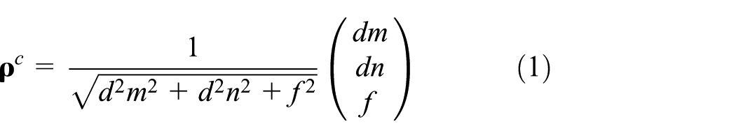
where
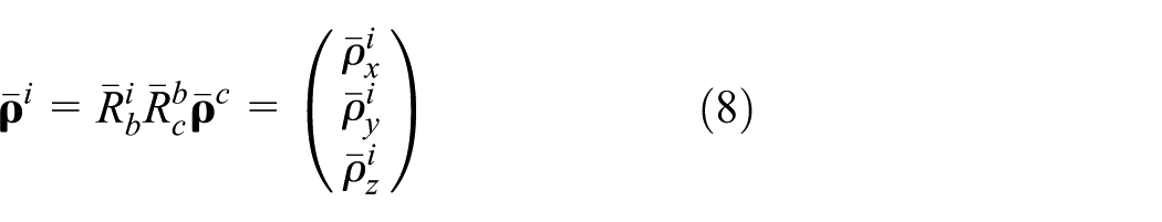
Let the attitude matrix of the satellite body frame with respect to the inertial frame be

This is the mathematical model of LOS measurement for video satellite. However
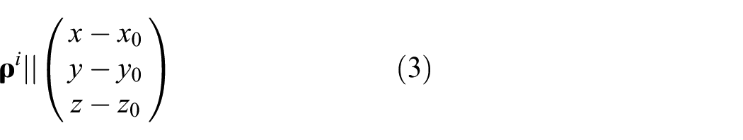
where
Equation (3) is the basis of positioning by LOS measurement.
Analysis of error sources
From the mathematical model of LOS measurement for video satellite, that is, equation (2), it is explicit that the LOS measurement error mainly comes from the attitude determination error, camera calibration error, and object detection error.
Attitude determination error
The attitude determination system of the video satellite uses the measurement data of the star sensor and the fiber optic gyroscope to determine the attitude matrix of the satellite body frame with respect to the inertial frame,

where
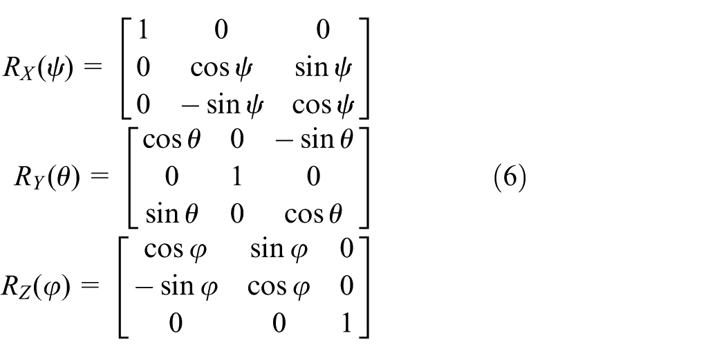
The 3-2-1 Euler angle of attitude error,

where RX(ψ), RY(θ), and RZ(
The variance of error Euler angle is determined by the technical indicators of the attitude determination system.
Camera calibration error
As a low-cost agile small satellite, the camera of video satellite is fixed on the satellite, and the motion of the optical axis is accomplished by attitude motion, which is different from the HEO infrared early warning satellite.14–16 Assuming that the 3-2-1 Euler angle of the camera frame with respect to the satellite body frame is

Design of video satellite tries to make
Object detection error
The object detection error is the detected coordinate error of the object in the image frame, mainly determined by the object detection algorithm, especially coordinate extraction method in detection algorithm. The object detection error is represented as
In addition, some researchers believe that the position error of the video satellite, that is, the coordinate error of the video satellite in the inertial frame, introduced by ephemeris error and time synchronization error, will also cause the LOS measurement error.17,18 However, equations (2) and (3) show that the position error of the satellite does not affect LOS measurement, but affects the final positioning error, that is, the coordinate error of the object in the inertial frame solved from equation (3), which is not within the scope of this article.
LOS measurement error formula
The LOS measurement error, in essence, is the angle between the actual LOS and the measured LOS.
The measured LOS
Let the actual LOS be

In this article, ξ is supposed to be small quantity which fits the engineering practice. When the camera is re-calibrated by the video images from the satellite, the attitude determination error has been introduced, so that the camera calibration error and the attitude determination error can be fused into the optical axis determination error, that is, the attitude error of the camera frame with respect to the inertial frame, which can be represented by a left multiplied error attitude matrix, δR

Similarly, assuming that

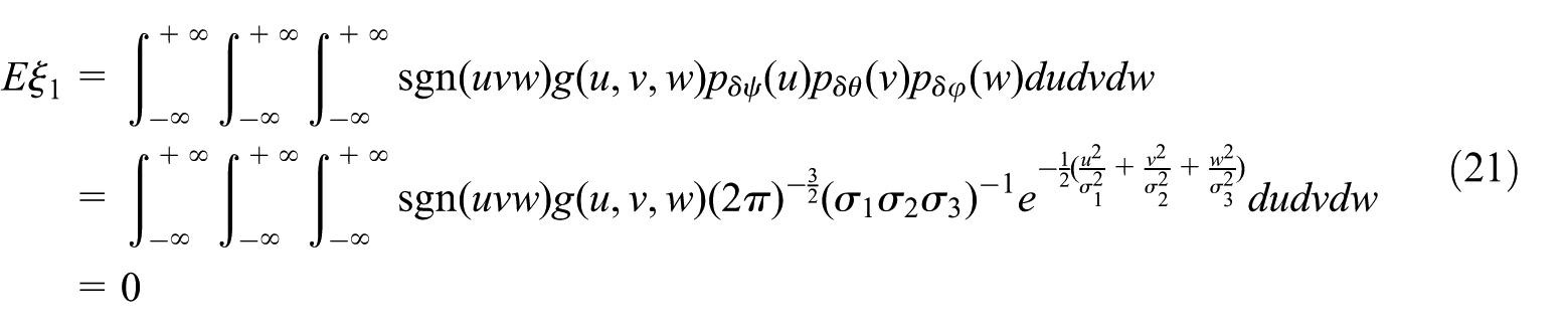
Obviously, the optical axis determination error and the object detection error are independent of each other. The LOS measurement error angle caused by the optical axis determination error and the object detection error will be calculated, respectively, below.
First, only the optical axis determination error is considered. Then, the actual LOS is given by

and

Consider the error angle

For

Substituting

into equation (15) gives

Let

then

Let

(a)
If

which is independent of the satellite attitude and the position of the object on image plane.
(b)
Otherwise, without loss of generality, let
If

Let

Then, the theoretical minimum error point of LOS measurement on image plane is given by
(c)
If

At this time, the theoretical minimum error points of LOS measurement on image plane are infinitely many. Let
Then, the theoretical minimum error points of LOS measurement on image plane are given by

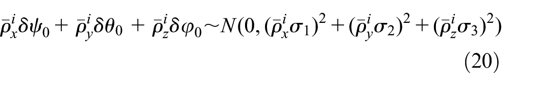
Using Chebyshev’s inequality gives

Then, the range of
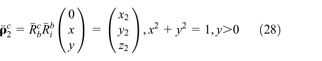
Then, consider the object detection error, which is denoted as

Diagram of ξ2.
For
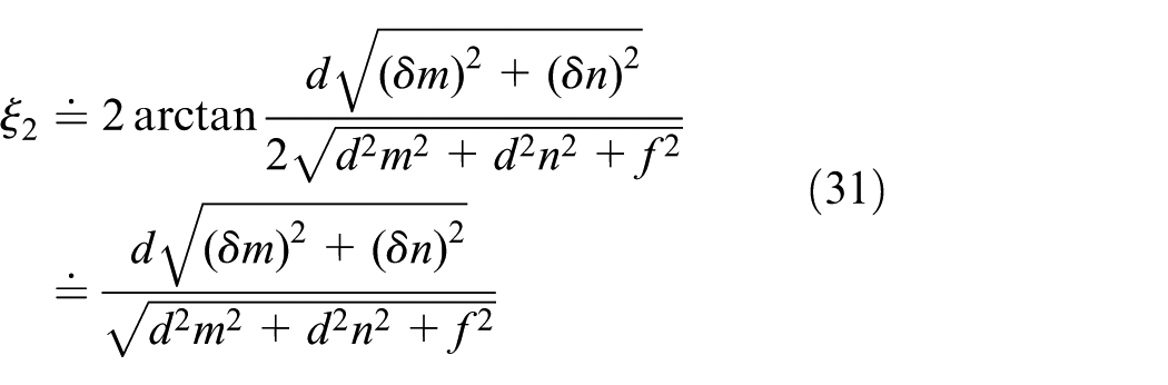
If
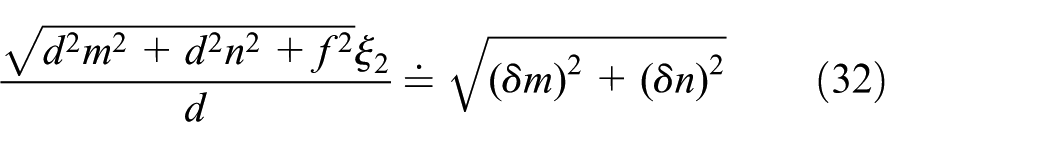
which shows that

We can obtain
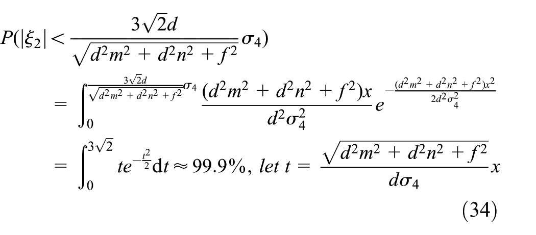
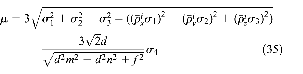
The error angle ξ1 caused by the optical axis determination error and the error angle ξ2 caused by the object detection error are independent of each other. These angles are actually error cone angles. Then
Simulation verification and analysis
Taking a certain video satellite as an example, the 3-2-1 Euler angle of the camera frame with respect to the satellite body frame calibrated by video images from the satellite is (1′20″, 2′10″, 2′20″). On-board camera resolution is 960 × 576. The size of pixel is 8.33 μm and the focal length is 1000 mm.
Approximation accuracy of ξ1
Equation (17) gives an approximation of ξ1. The accuracy of the approximation can be scaled by the approximation error, verified by Monte Carlo simulation.15,17 Generate random numbers
Let the 3-2-1 Euler angle of the satellite body frame with respect to the inertial frame be (45°, 45°, 45°) and the coordinate of the space object on the image plane be (30, 20). Calculate the error of approximation after 10,000 Monte Carlo simulations, as shown in Figure 3.

Approximation error of ξ1.
Simulation results show that the approximation accuracy reached 100th of a second. The approximation is reasonable.
Statistical properties of ξ1
As mentioned above,
Let the 3-2-1 Euler angle of the satellite body frame with respect to the inertial frame be (45°, 45°, 45°) and the coordinate of the space object on the image plane be (30, 20). Draw the statistical histogram of Monte Carlo simulation results, as shown in Figure 4, which shows that
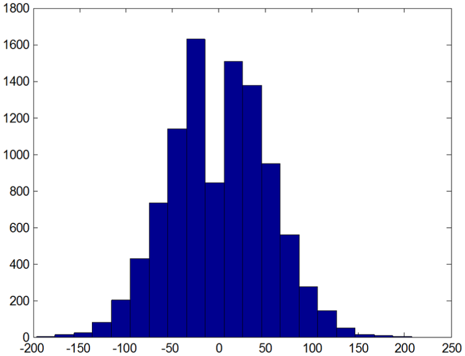
Statistical histogram of
Let the 3-2-1 Euler angle of the satellite body frame with respect to the inertial frame be
Then, change the coordinate of the space object on the image plane away from the center. Let it be (420, 216). Similarly, perform 10,000 Monte Carlo simulations at each 3-2-1 Euler angle of 343 groups and calculate
Simulation results show that the range of
Validation test of LOS measurement error angle range
Equation (35) gives the error angle range of LOS measurement, whose validation will be tested by Monte Carlo simulations.
Generate random numbers of given distribution and substitute them into the following equation to calculate the actual LOS
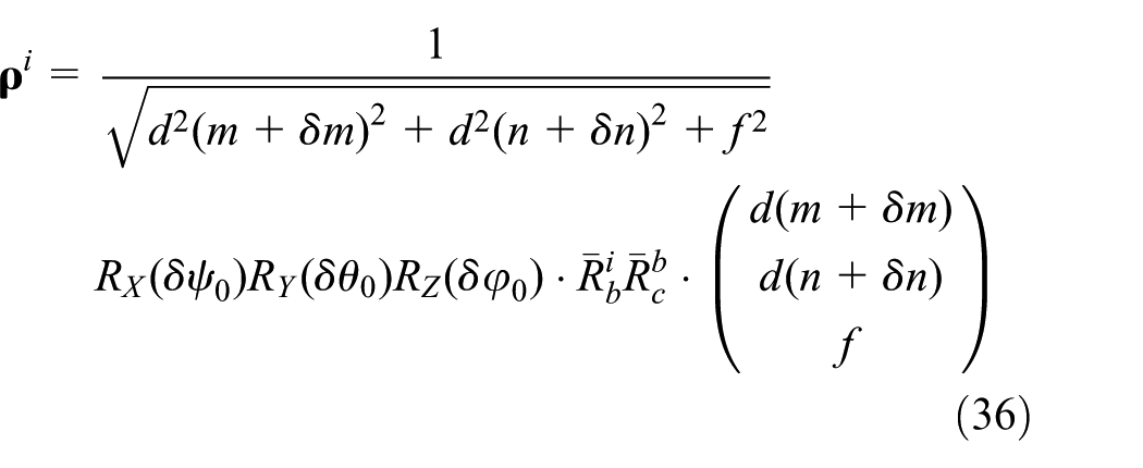
Then, calculate the error angle
Let the coordinate of the space object on image plane be (30, 20) and the 3-2-1 Euler angle of the satellite body frame with respect to the inertial frame be
Then, change the coordinate of the space object on the image plane away from the center. Let it be (420, 216). Similarly, perform 10,000 Monte Carlo simulations at each 3-2-1 Euler angle of 343 groups and calculate
Simulation results show that the range of
Minimum error points of LOS measurement on image plane
Equation (35) gives the error angle range of LOS measurement for video satellite, which consists of two terms, the error range caused by the optical axis determination error and the object detection error.
When the on-board camera is a narrow field camera, the error range caused by the object detection error is about two orders of magnitude, less than that caused by the optical axis determination error; so, the error angle range of LOS measurement is mainly determined by the first term, that is, equation (22). Equations (8) and (22) show that the effect of the satellite attitude and the position of the object on image plane are highly coupled to the error range of LOS measurement.
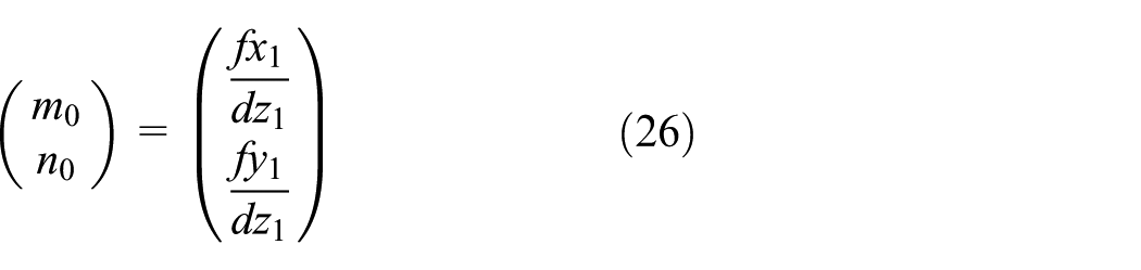
If
Equations (25) and (26) actually solve the intersection of the Z axis in the inertial frame and image plane. Rotation around the Z axis does not change the direction of the Z axis, and the change in the yaw angle does not affect the position of the intersection. Without loss of generality, let the yaw angle be 0.
But since the on-board camera is a narrow field camera, the intersection is hardly in the scope of image plane. For example, under the simulation conditions given in this section, the camera on the certain video satellite is a narrow field camera, whose field of view is only 0.4582°×0.2749°. If the 3-2-1 Euler angle of the satellite body frame with respect to the inertial frame is (0, 0, 0), the minimum error point is (75.6928, −81.4520) by equation (26). If the 3-2-1 Euler angle is (0°, 30°, 0°), the minimum error point is (−765780, −378.16), which is far beyond the scope of image plane. Let the 3-2-1 Euler angle be
However, when the on-board camera is a wide field camera, the second term of equation (35) is the same order of magnitude as the first term. At this time, the second term cannot be omitted. Take a wide field camera as an example, whose focal length is 4 mm, size of pixel is 4.2 μm, and resolution is 1280 × 1080. Then, its field of view is 67.80°×59.11°. Let the 3-2-1 Euler angle be

Minimum error points of LOS measurement on image plane under 343 groups of 3-2-1 Euler angle.
In summary, whether the on-board camera is a narrow field camera or a wide field camera, simulation results show that the effect of the satellite attitude and the position of the object on image plane are highly coupled to the error range of LOS measurement.
Conclusion
In this article, the LOS measurement error by video satellite is deeply researched and derives concise and practical results. A mathematical model of LOS measurement is established using the transformation from image plane to object position, which shows that the LOS measurement error mainly comes from the attitude determination error, camera calibration error, and object detection error. The camera calibration error and the attitude determination error are fused into the optical axis determination error based on their relationship. The error of LOS measurement caused by the optical axis determination error and the object detection error is calculated, respectively, and their statistical properties are studied. Finally, a concise and practical analytic formula of the error range of LOS measurement is derived. Simulation results verify the theoretical analysis, and the minimum error points of LOS measurement on image plane are researched. It is indicated that the effect of the satellite attitude and the position of the object on image plane are highly coupled to the error range of LOS measurement.
Footnotes
Handling Editor: Yangmin Li
Declaration of conflicting interests
The author(s) declared no potential conflicts of interest with respect to the research, authorship, and/or publication of this article.
Funding
The author(s) received no financial support for the research, authorship, and/or publication of this article.