
Abstract
A quasi-static method to analyze equilibrium path and trajectory deflections for the load of polar crane in nuclear power plant is presented based on three-dimensional analyses. The governing equations of equilibrium path and the compatibility conditions of the rope–pulley system are provided in the method; properties and formulations of the variables involved in these equations are studied in detail. A method to describe general rope–pulley system is given, and a numerical method is derived to solve the common tangent between spatial pulleys, which was conforming to the rope reeving. Moreover, the rope lengths wound by the drum and left in the system are computed, and the transitive relation for rope velocities between two sides of the pulley is derived. Two numerical examples prove that the proposed method is reasonable and valid, and to a large extent, the method is universal and can be applied to general rope–pulley systems.
Keywords
Introduction
Polar cranes in nuclear power plants (NPP) are type of special cranes for replacing the reactor fuel or maintaining the heavy equipment. Due to the special working circumstance, the cranes should locate the load in a high degree of accuracy. For example, the lateral displacement of the load for some type of polar cranes in service should not be even more than 5 mm while lifting 10 m height. To meet the accurate and reliable requirements, one should know how the load to motion when the crane works.
At present, there are many researches about cranes. Some studies1–4 focused on the control of the load deflection considering the trolley moving while the crane hoisting or lowering, while some studies5–8 discussed the dynamic responses of the crane structure. These studies solved many problems about the operation schemes and structural designs of the cranes. However, most of these studies simplified the rope–sheave system as a pendulum or double pendulum system or considered the plurality of ropes as a flexible cable,9–12 which is obviously not adapted to the cranes requiring high accuracy. In fact, the load’s movement is determined by the interactions between ropes and pulleys in the hoisting system. Although many achievements on the interactions have been accumulated, much work about combining the achievements with the large hoisting system of specific characteristics remains to be finished.
McDonald and Peyrot13,14 presented a pulley element for exact analysis of cables rolling on pulley, in which the internal forces and the tangent stiffness matrix corresponding to an equilibrium configuration are provided. Based on the study, the further work aiming at the possible application to practical cable systems is advanced, 15 and the finite element analysis with three-node element is conducted. 16 However, the rope–pulley system was treated in a plane while deriving the internal force equilibrium in these papers. Aufaure17,18 presented a finite element formulation for a length of cable passing through a pulley to study the deformation and dynamic behavior of structures and treated the pulley as a particle to analyze the movement, which neglected many details. Zhou et al. 19 developed sliding cable elements and pulley models using the massless spring approach for the analysis of parachute systems. By previously creating markers in the MSC.ADAMS software package, Wang et al. 20 analyzed the rope wound along helix based on the concentrated mass theory with multi-degree of freedom and established a parametric model which is applicable to the case of less pulleys. Ju and Choo 21 proposed a parameterized super element formulation for modeling the multiple-pulley cables; however, there was no further study about the movement of the pulley. Hong and Cipra 22 presented a program method to analyze the motion of complex cable–pulley mechanism, which could obtain the relationships of each variable; however, the method could not be applied to spatial rope–pulley system.
The trajectory deflections of the load are crucial parameters for the polar cranes requiring precise location. Meanwhile, the trajectory deflections are systematic, which are determined by the factors such as the operating modes, the models, and layouts of pulleys and the reeving ways of ropes. Due to the position changes of the movable pulleys in hoisting, the tension of each rope changes constantly, which makes it difficult to solve the load trajectory. Based on three-dimensional (3D) analyses, this article presents a quasi-static method for analyzing the load trajectory deflections of polar crane in NPP taking into account the detailed structure of the hoisting mechanism. The method considers the reeving way of each rope that connects spatial pulleys and then can accurately calculate the forces on the hook block. Compatibility conditions of the rope lengths are provided to make the solving conditions complete. In the method, the load trajectory under uniform lifting or lowering speed is discussed through analyzing the attitude and displacement of the hook block.
Equilibrium path equations
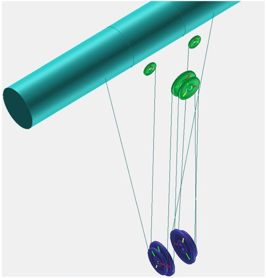
Generally, the hoisting equipment of the polar crane in NPP consists of drum, fixed pulleys, movable pulleys mounted on the hook block, and ropes reeving through the pulleys. Figure 1 shows the schematic diagram of the main hoisting mechanism for some type of polar crane in NPP. We can see that two ropes start from the drum, go through the pulleys in a certain order, and anchor to fixed points. The movable pulleys are identified by numbers 1–12 and the fixed pulleys by numbers 13–24, and number 22 identifies a guide pulley which can be treated as a special fixed pulley. The load ascends or descends in accordance with the drum winding or releasing the ropes.
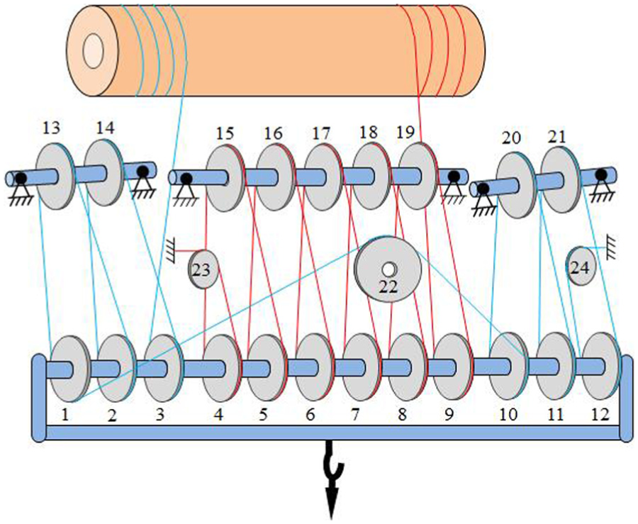
Schematic view of the main rope–pulley system for polar crane in NPP.
Like most of the cranes, polar crane in NPP cannot ensure the load hoisting in the vertical direction. The lateral displacement of the load is the trajectory deflection. The bigger accelerator of the hook block causes greater deflection in general. Therefore, while the system is working, the operators strive to keep the motion smooth for the hook block. Under this condition, the external forces on the hook block are in equilibrium, and the trajectory of the hoisting point is the equilibrium path of the polar crane. As the directions of the rope tensions probably change while hoisting, the trajectory of the load would naturally be out of vertical. As a result, the trajectory deflections are irrelevant to the operation process but mainly determined by the mechanic designs, the relative positions of the drum and pulleys, and the reeving ways of the ropes, which should necessarily be taken into account in designing the polar crane in NPP.
The external force on the hook block contains load weight, own gravity, and the contact forces acting on the movable pulleys, which can be equivalent to the rope tensions at both sides of the pulleys.
To describe the load trajectory, we create a reference coordinate system


where
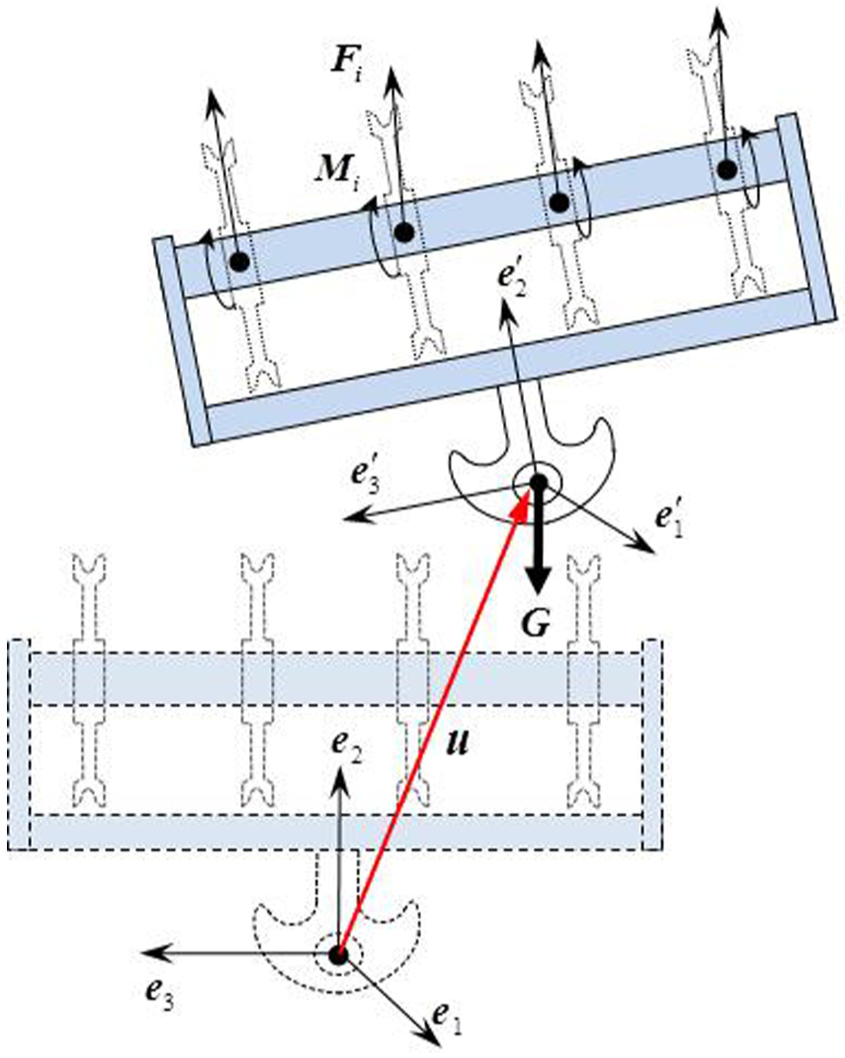
Motion and stress of the hook block.
The variable
The external forces on the hook block include the weight


where

It can be seen that the directions of the forces in equation (5) is coupled with angles
Tangent between spatial pulleys
While hoisting, the rope starts to contact the pulley at the rope inlet point and to leave the pulley at the rope outlet point. The positions of the inlet and outlet points, which determine the application points and directions of rope tensions, are essential parameters to describe the rope–pulley system. Comparing to the load, the rope connecting two pulleys has a very small mass and can be considered as a straight line. Besides, the width of the pulley groove is quite small in contrast with the hoisting height. Therefore, we can treat the pulleys as spatial circles and the rope as common tangent between the circles to solve the tangent points, which are the inlet point and outlet point.
As shown in Figure 3, suppose two spatial circles with radii


Common tangent of two spatial pulleys.
Since the common tangent is perpendicular to the radius vectors, we have


Thus, the equation for common tangent is

where the coefficients
There are four types of common tangent between two spatial pulleys, which are separately called the common tangent of right external, left external, right internal, and left internal corresponding to k = 1, k = 2, k = 3, and k = 4 as shown in Figure 4. It is meaningless for the solution inconsistent with the type of the common tangent. The nonlinear equation (11) has four solutions, and we had to consider the initial value approximate to the specified solution as much as possible to obtain the specified solution.

Types of the common tangent between pulleys.
While the two spatial pulleys are coplanar or paralleled to each other, the equation for common tangent has analytical solutions. We take the corresponding analytical solutions as the initial value to solve equation (11) for the specified numerical solution, which is proved to be feasible and effective. How to solve the initial value is expounded in Appendix 1, and a number matrix to describe the rope–pulley system is introduced in detail, which is convenient for programming solution.
Transmission of tensions at two sides of pulley
The rope in the branch can be divided into two parts: ropes wrapped on pulleys and ropes hung in space. As for pulley i, the dividing points of the rope are the inlet point and outlet point denoted by
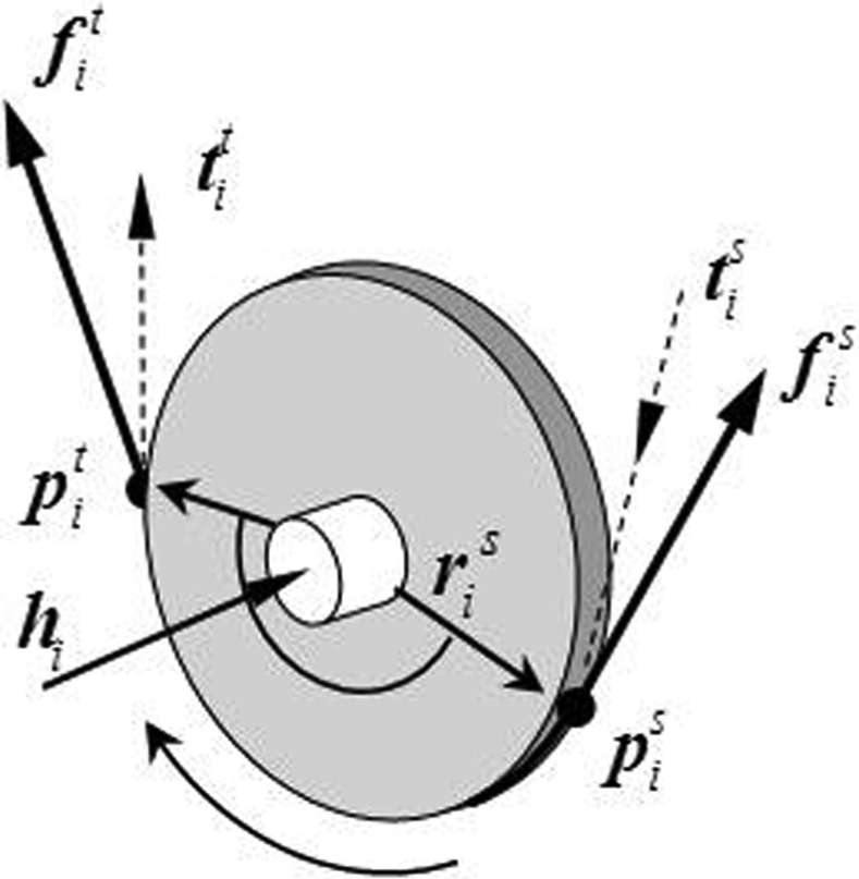
Inlet point and outlet point of pulley.
The rope changes from straight to curving at inlet point of the pulley, and at outlet point changes from curving to straight. Because of the rope’s some resistance to deformation, there is a small transition curve between the straight rope and the curving rope. The transition curve diminishes the distance between the straight rope and the pulley’s center at the outlet point, otherwise extends the distance at the inlet point. The diminished distance is denoted by

Stiffness resistance of rope.
Regarding the pulley as a rigid body, the resultant force


where
As shown in Figure 5, the tangent directions at the inlet point and the outlet point in the pulley’s surface can be expressed as follows
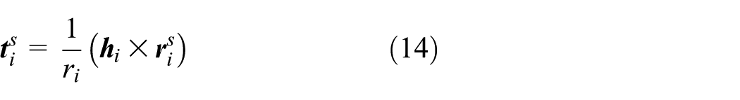

The corresponding tangent components of the rope tensions are


Dot-multiplying both sides of equation (13) by the unit vector

In fact, the left term of the equation is resisting moment, which is caused by friction between the pulley and the shaft and can be expressed by the frictional resistance coefficient

In practical engineering,
where the tension increment is caused merely by stiffness effect of the rope, and
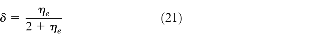
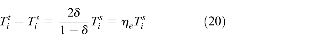
Taking account of all the resistances, the relationship of the tensions at both sides of the pulley will be derived by equations (18)–(21) as follows

where
According to equations (16) and (17) and the previous analysis, the rope tensions

where
The gravity of the hook block is sufficient to tighten the rope hung in space. Therefore, the tangent direction between pulleys can be considered as the tension direction of the rope, and the tangent point is the inlet point or the outlet point.
Without considering rope mass, the tensions of the rope hung in space are equal at every point, and the rope tensions at both sides of pulleys satisfy equation (23). Therefore, giving the rope tension T that connected the drum, we can obtain the tension of each rope hung in space in sequence as shown in Figure 7.

Directions of rope tensions and transitive relationships.
Compatible condition of rope length
As shown in Figure 8, a duplex drum is usually used in practical engineering, which has a groove of helical line and is difficult to confirm the trajectory of the rope tangent point on the drum. In this section, compatible conditions of rope length are proposed to solve the positions of the rope tangent points on the drum.
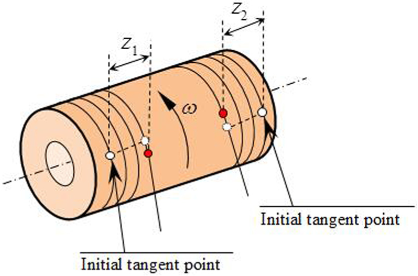
Rope length wound by the drum.
The rope usually has very high tensile strength, and the elongation can be neglected. If the longitudinal displacement of the tangent point is
where
As the starting points of the two ropes are connecting to the same drum, the winding loops of the two rope branches are the same at one moment. However, the instantaneous orientation angles

where
By eliminating

The total rope length in the branch is

where n is the number of the ropes in space;

In general, the rope bypasses movable pulley from the bottom and fixed pulley from the top as shown in Figure 9. The vectors from the pulley’s center to the two tangent points are denoted by


Rope wrapped on pulleys: (a) movable pulley and (b) fixed pulley.
The wrap angle on fixed pulley is

Then, the length of rope wound by the drum should equal the length that reduced in the branch. Then, we have
where
In the above analysis, we know that there are nine unknown parameters to resolve: seven degrees of freedoms to determine the movement of the mechanism (
Moment equilibrium for guide pulley
In order to avoid rope interferences and reduce deviation components of the rope tensions, a guide pulley is usually used to connect two movable pulleys with large distance span. Different from ordinary pulleys, the guide pulley is connected on a horizontal shaft

Guide pulley.
While the load is hoisting, the rotation angle of the guide pulley around the horizontal shaft is changing and then the angle is the 10th unknown parameter, which means that a supplementary equation should be provided to confirm the equilibrium path.
If the guide pulley rotates around the horizontal shaft by an angle of

where the unit vector
The vector from the pulley’s center to the point C is

where b is the distance between the pulley’s center and the hanging point.
Neglecting the friction of the horizontal shaft, the reaction moment on the shaft should be zero and we have
where
Angular speed of pulley
Rope speed is one of the important designing parameters in many aspects, such as the selection of wire rope, the designing of pulleys, the power system of drum, and so on. The rope speed cannot be estimated by multiplying factor for the hoisting system that requires precise control. Based on the velocities of tangent points obtained in previous sections, a method to resolve the rope speeds and the angular speeds of pulleys along the rope branch is proposed in this section.
Figure 11 shows a pulley with radius r and center

where

where

Rope speed and angular speed of pulley.
The change rate of

where

where

Neglecting the rope elongation, we have that

The equation is the relationship of the angular speed

and the difference between

After solving the change rates of the tangent points, the transitive relationship of the rope speeds at sides of pulley can be obtained by equation (42). In the rope branch, the speed of the rope with the end anchored to a fixed point is equal to zero; therefore, starting from the end of the branch, one can obtain the rope speeds and the angular speeds of the pulleys successively by equations (40)–(42).
Numerical examples
Auxiliary rope–pulley system of the polar crane for NPP
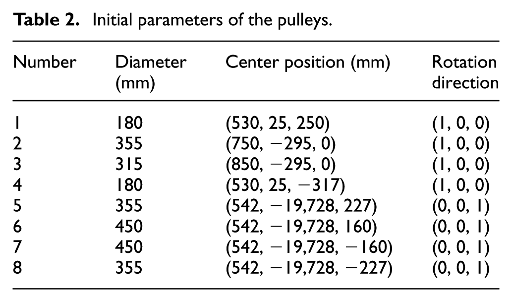
To verify the methodology presented in this article, we developed a general MATLAB program, by which parameters input, model calculation, and processing can be carried out, and an auxiliary rope–pulley system with less pulleys is analyzed first as shown in Figures 12 and 13. The parameters of the system are shown in Tables 1 and 2. The positions of the drum and pulleys are given in the global coordinate (X, Y, Z) and X toward front, Y toward up, and Z toward left. The weight of the hook block is 1000 kg. The centroid of the hook block is (0, −20, 0) m and the hanging point is (0, −20.24, 0) m in the global coordinate. The working condition that hoisting a load of 20 tons to arise 15 m was studied. The efficiency coefficient of pulley is 0.98, and the frictional resistance coefficient is 0.01455.

Schematic diagram of auxiliary rope–pulley system.
Simulation model of auxiliary rope–pulley system in MATLAB.
Initial parameters of the drum in auxiliary rope-pulley system.

Initial parameters of the pulleys.
The trajectories of the mount point as well as the rotational angles of the hook block versus the height are depicted in Figure 14 in blue solid curve, and the red dotted curves in this figure denote vertical lines crossing the initial mount point. The distances between the two kinds of curves signify the trajectory deflections.
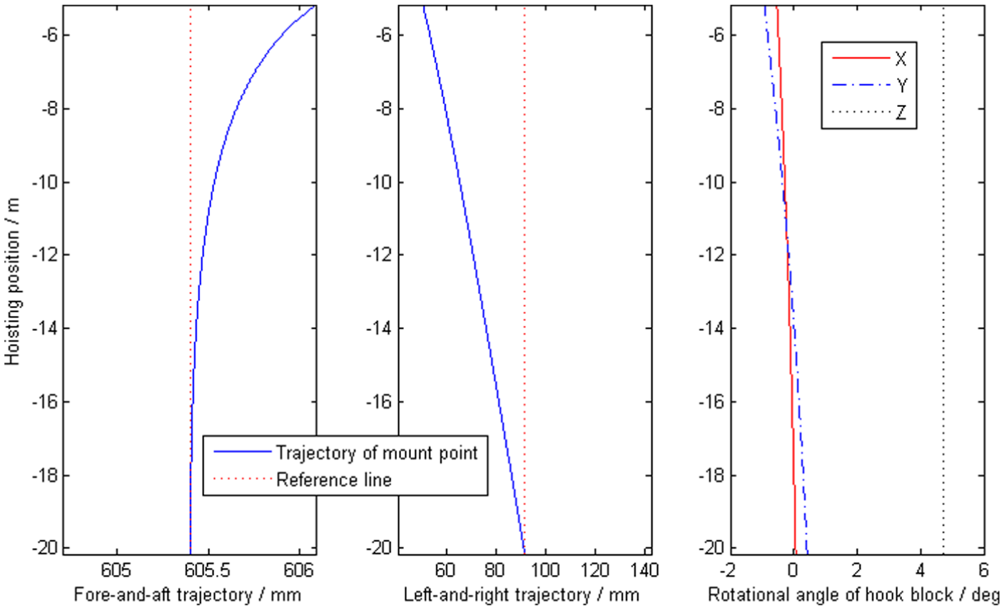
Trajectory deflections and rotational angles of the mount point.
It can be seen that (1) the trajectory is not exactly vertical and the deflections get greater and greater in general. (2) Because the rotation directions of the movable pulleys are along the Z direction, which is the direction of the frictional resistance moments, the rotational angle around Z-axis is greater than those around X-axis and Y-axis.
Because of the roughly right-and-left symmetrical measurements of the rope–pulley system, the positions of the pulleys, and the reeving way of the rope, the rope speeds almost keep unchanging relative to the hoisting speed, and the curves shown in Figure 15 are nearly horizontal lines whose values approach to the corresponding multiplying factors. The curves in Figure 16 are the rope speeds at the tangent point of the drum, which become smaller slightly as the space ropes diverge from the vertical.
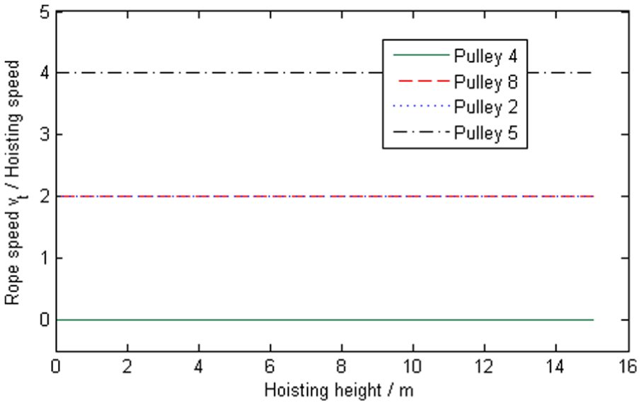
Rope speeds at outlet points of pulleys.

Rope speeds on the winch.
Figure 17 shows that the orientation angles on the drum become larger as the hook block gets closer to the drum. From Figure 18, it can be seen that the rope tensions on two sides of the drum are not equal as the two rope branches are connected to fixed points directly. However, the sum of the two tensions equals approximately to 1/4 of the weight of the load and the hook block.
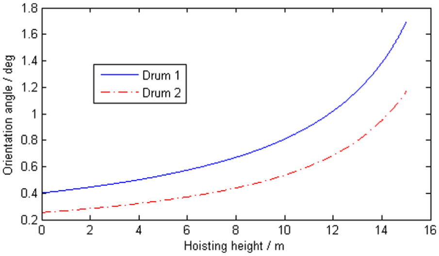
Orientation angles on the winch.
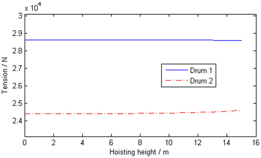
Tensions at two sides of drum.
Main rope–pulley system of the polar crane for NPP
In this section, numerical examples for the main rope–pulley system as shown in Figure 1 are given to verify the application of the methodology. The global coordinate is established as that in section “Auxiliary rope–pulley system of the polar crane for NPP.” The hook-block-fixed coordinate is established at the centroid of the hook block, whose initial origin is (0, −45, 0) m in global coordinate. The initial parameters about the drum and pulleys are displayed in Tables 3–5. Among the parameters, the positions of the movable pulleys are given in the hook-block-fixed coordinate, while the others are given in the global coordinate. The weight of the hook block is 5000 kg as well as the hanging point is (0, −1.222, 0) m in the hook-block-fixed coordinate.
Initial parameters of the drum in main rope-pulley system.

Initial parameters of fixed pulleys.

Initial parameters of movable pulleys.

In order to compare the influence of different load weights on the trajectory deflections, we analyzed the equilibrium paths of the polar crane in NPP, which lifted 30 m height with weights of empty, 5, 20, 200 tons, respectively.
The trajectory deflections of the hanging point in the left-and-right direction and fore-and-aft direction versus the lifting height are shown in Figures 19 and 20. It can be seen that (1) the deflections affected by lifting weight are small, and (2) the deflection under empty load is a little greater than that under some lifting weight.

Deflections in the left-and-right direction.
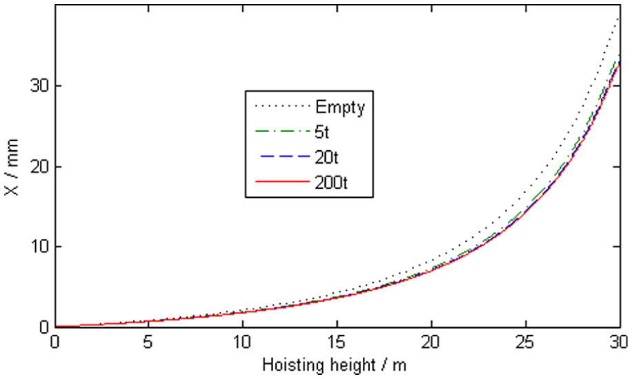
Deflections in the fore-and-aft direction.
To compare the effects of lifting and lowering on the trajectory deflections, we analyzed the equilibrium path of the polar crane, which first lifted 20 m height with 200 tons weight and then lowered 20 m to the initial height. The trajectory deflections in the left-and-right direction and fore-and-aft direction are shown in Figures 21 and 22. It can be seen that the deflection in lifting is greater than that in lowering.

Contrast of lifting and lowering for deflection in the left-and-right direction.
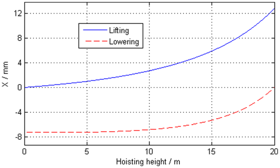
Contrast of lifting and lowering for deflection in the fore-and-aft direction.
Discussion
Through the previous analysis, we know that the measurements of the pulleys and drums as well as the layouts and the reeving ways of the rope–pulley system determine the directions and magnitude relations of the rope tensions and thus affect the trajectory deflections of the load. The trajectory deflections are systematic and have several key properties as follows:
The deflections and their increment speeds become greater as the load gets nearer to the top. This is because the distance between fixed pulleys and movable pulleys becomes closer, and some rope directions diverge from the vertical, which increase the horizontal components of the rope tensions, thus the greater deflections are caused.
Because the deflection is systematic, different lifting weights have little influence on the deflection.
The deflections in lifting are greater than that in lowering. The reason is that the outlet side and inlet side of the pulleys in lowering is contrary to that in lifting, and the ropes approached to vertical while lowering which reduced the horizontal components of the rope tensions.
Conclusion
There are systematic trajectory deflections for the load of the polar crane in NPP. The model selections of the pulleys and drums, the layouts of the system components, and the reeving way of ropes would affect the load trajectory of the polar cranes. To reduce the trajectory deflections and locate the load precisely, a reasonable mechanical design for rope–pulley system is necessary. This article provides a quasi-static method to solve equilibrium path of the hook block, which is a systematic method and takes into account the detailed structure of the rope–pulley system. The method and related program that provide a simulation test platform can be a reference for the mechanic design, especially the model selections of the pulleys and drums, the layouts of the system components, and the reeving way of ropes.
Because the tension of each rope changes constantly as the load hoisting, to solve the equilibrium path of the hook block is rather difficult and complicated. This article made some attempts on the problem. However, the mass and the deformation of the rope are without considering, and the dynamics and control of the load are uninvestigated, which can be the target of further research and development.
Novelty indication
At present, there are many researches about the load trajectories of cranes. However, some of these researches considered the load and the plurality of ropes as a flexible pendulum, and some of them made many simplifications for the rope–pulley system, and the results cannot meet the high accuracy requirements in locating the loads for the polar cranes in NPPs. This article presents a quasi-static method to analyze equilibrium path and trajectory deflections are systematic for the load of polar crane in NPP based on 3D analyses. A numerical method is derived to solve the common tangent between spatial pulleys, which was conforming to the rope reeving. As the method considers the reeving way of each rope that connects spatial pulleys and the tension transmission at two ends of each pulley, then it can accurately calculate the forces on the hook block exactly. The systematic method is theoretical, and the simulation results verify the rationality of the method, which can be a reference for the mechanic design such as the model selections of the pulleys and drums, the layouts of the system components, and the reeving way of ropes. To a large extent, the method is universal and can be applied to general rope–pulley systems.
Footnotes
Appendix 1
Four analytical values for the tangent points of two paralleled pulleys are written in the following. As for the external tangent, we have
where
As for the internal tangent,
where
Taking these analytical solutions as the initial value, one can make the numerical solution of equation (11) in accordance with the reeving way between the rope and pulleys.
With the pulley numbers and the types of common tangents between the spatial pulleys, we can describe the rope–pulley system by a number matrix. For the main rope–pulley system as shown in Figure 1, one could take the following two matrixes to describe the reeving ways of the two rope branches, respectively
and
The first row stores the numbers of the pulleys through which the rope reeves from the drum in sequence, while the second row stores the numbers of the corresponding tangent types as shown in Figure 4. For example, the first number 3 in
As for the auxiliary rope–pulley system as shown in Figure 16, the matrix can be written as follows
Handling Editor: Jining Sun
Declaration of conflicting interests
The author(s) declared no potential conflicts of interest with respect to the research, authorship, and/or publication of this article.
Funding
The author(s) disclosed receipt of the following financial support for the research, authorship, and/or publication of this article: This work was supported by the National Natural Science Foundation of China, P. R. China (no. 11372057).