
Abstract
When a robot is working properly, it is possible to collide with people or objects entering its working space. This research is different than usual control algorithm. It proposes a universal algorithm for sensorless collision detection of robot actuator faults to enhance the security of the robot. On the basis of the dynamic model, a classical friction model to ensure the accuracy of the whole dynamic model is introduced. This collision detection algorithm can conduct without any external sensors or acceleration and realize the real-time detection just needs to measure the motor current and the location information from the encoder of the robot joint. The value of external torque τext was used to compare with the threshold to detect the collision. After using the proposed collision detection method, the two rotational (2R) planar manipulators can detect the slight collision reliably. The experimental results and performance comparisons show that this sensorless collision detection algorithm is simple and effective. It can be promoted to any other type of robot arm with more degrees of freedom.
Introduction
For obtaining a compliant flexible design of robot which has the capability of interacting and collaborating with human, it should fulfill some parameters to achieve this task. These robots should be flexible and compliant to achieve the collaboration and interaction feature. This feature needs some consideration in the mechanical structure design of the robot and the choosing of hardware devices. The most important side is implementing complex control techniques. We will refer to some of the recent research work and techniques for both mechanical design and control side. And in the top of all these parameters, we need to consider the safety issues. Safety should be the dominant parameter for such robots design.
For achieving this, we need to utilize actuators which are capable of modulating torque and impedance (stiffness and/or damping) simultaneously, continuously, and independently. 1 There is some research work in that direction. Automatic collision avoidance is achieved by the control design at the kinematic level exploiting the joint space redundancy.2,3 The variable impedance actuators (VIA), series-elastic actuators (SEAs), 4 and variable-stiffness actuators (VSAs) 5 were used in these researches. In Qiu et al., 6 they combine vision compressive sensing, brain–machine reference commands, and adaptive fuzzy control to develop a teleportation control system for exoskeleton robots. Moreover, harmonic drives could be utilized for this task. These actuators can reach the required features of the robot but on the most important side, it needs complex control strategies.
How to enhance the security of the industry robot can begin at collision detection. There are some researches about it and some researchers acquired certain results. The most effective, fast, and simplest method of detecting the collision of the robot is adding external sensor.7–9 Although this method can detect the collision force accurately, it can just detect the place and the high-precision sensors are expensive. There are fewer companies that can afford so high price sensors equipped on the robots. Phan et al. 10 introduced an internal sensor measurement method. It captures the torques of each joint and the values of each encoder. The driving moment of the robot in the motion can be calculated by the dynamic model. Comparing the calculated torque and the captured torque, the collision can be detected. This method needs to calculate the first and second derivatives of the position. This process may lead to the noise and will affect the accuracy of the system. Yamada et al. 11 and De Luca and Mattone 12 introduced a detection method based on the kinetic momentum. This method regards the collision as the system fault. It can detect the collision perfectly, but it has some interaction effects on timeliness and accuracy of tracking the external force. It is hard to have good timeliness and accuracy simultaneity. There are also other detection collision/interaction techniques without using external sensors, such as in De Luca and colleagues.13,14
The sensorless collision detection is the latest research direction. This technique does not use any extra sensors, such as torque sensors or accelerometers, and it is proposed in this research. A dynamic model and a friction model of the robot joints are also developed for this purpose. This research can realize the real-time detection just needs to measure the motor current and the location information from the encoder of the robot joint. The observed value of residual error was used to compare with the threshold to detect the collision. In order to verify the accuracy of the algorithm of collision detection method, a 2R planar manipulator was built. We made some experiments on it. The experimental results show that the collision can be detected reliably and the manipulator can stop immediately when the collision occurs.
Collision and interaction detection
For the robot to be able to collaborate with humans physically, there should be a technique with certain control strategy to detect the physical collisions and interactions. This research realizes the real-time detection just needs to measure the motor current and the location information from the encoder of the robot joint. The observed value of residual error was used to compare with the threshold to detect the collision.
Rigid body dynamic model
The dynamic model of robot mechanism can be described as

When a robot is working properly, it is possible to collide with people or objects entering its working space. Then the dynamics equation is

The dynamical parameters of each joint can be calculated from the computer-aided design (CAD) data after added the materials on the robot. The position vector
The joint torque
There are many types of research on the acceleration value
By monitoring the external torque τe, collisions can be detected. However, equation (2) cannot be directly used to compute τe, since the acceleration value
The dynamic model based on the generalized momentum
The generalized momentum of the robot can be defined as

This equation (3) satisfies the first-order equation by taking the derivative of

Knowing that

The dynamic model can be represented as
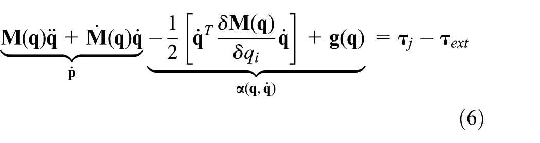
where the components

Rearranging equation (6), the new dynamic model can be obtained as

Estimation of the joint torque
In this research, the joint torque based on the motor torque is generally connected with the motor input current. The joint torque

The transmission of the collaborative robot joint.
As we know, the motor torque

Tc is the motor torque constant, which can be got in the motor manual.

where n is the speed reduction ratio and

where

Defining the residual error
By calculating the residual of the joint torque, it will be easy to detect the variation which might happen in the joints due to interaction or collision.
Defining the residual

We can estimate vector
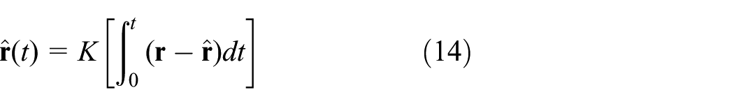
The residual

where the position vector
We can estimate
Friction model for the joint
Friction is a complex nonlinear physical phenomenon, occurs between the contacting surfaces of two objects with relative motions. The friction occurs in all of the mechanical systems and has important effects on the performance. Now, due to the friction with the highly nonlinear characteristic, it often leads to steady-state error, limits cycle, and reduces the performance indexes of the system. In this research, we consider three main frictions. The static friction τs describes with the no relative motion but with the trend of relative motion. In general, when an external force τe is less than the maximum static friction force τs, the static friction force will equal to the external force τe, but with the opposite direction. When the external force τe is equal to or greater than the maximum static friction force τs, the static friction force will equal to the maximum static friction force τs, the direction is different to the external force. Then, the friction τf can be described as

The Coulomb friction τc is proportional to the normal load τN, with the opposite direction and does not depend on the area of contact,

Current measured through Hall Effect sensor
The motor current should be measured, as to be able to estimate the robot joints torque without using external force/torque sensor. There are few techniques used for measuring the current flow. In this research, we propose using a Hall Effect sensor.
A current-carrying conductor is placed in two different fields. One is the no magnetic field and another is the magnetic field as shown in Figure 2(a) and (b). We can see some difference in electric potential. It will be perpendicular to the magnetic field and the direction of current flow. The Hall Effect sensor can measure the large currents with low power dissipation.

Block diagram for Hall Effect principle and collision reaction strategy: (a) no magnetic field, (b) magnetic field, and (c) collision reaction strategy.
When a robot detects the collision, it must perform an appropriate reaction to minimize the impact. In this research, we propose a reaction strategy for the collision conditions as shown in Figure 2(c).
Embedded system control architecture
The robotics control architecture design nowadays tends to be based on embedded systems in many applications. The embedded systems real-time capabilities made the reliable system to be utilized in most of the robotics applications. There are some limitations for the commercial robotics control systems. The commercial software is usually sold with the hardware. Most of these products just have the applications on position control. Lacking alternative extensibilities make it difficult to suit of our method. Therefore, it is impossible to extend the functionality of the robot. For these reasons, we propose a real-time embedded system based on the open source.
The proposed hardware control system design is shown in Figure 3, and the system hardware consists of the following.

Block diagram for hardware design.
Field programmable gate array
Flexible hardware such as field programmable gate array (FPGA) is currently considered an appropriate solution to increase control performance. 22 Due to its re-programmability, FPGA technology combines low-cost development with a rising integration density 23 making it well highly suitable for embedded systems. The success is a natural consequence of cost reduction, low power consumption, reliability, real-time characteristic, and significant control performance improvement by dedicated parallel computations.24,25
The FPGA is used in our system as a primary robot control system. This controller is responsible for handling all the control routines and algorithms which need real-time capability such as,
Acquiring the robot internal parameter;
Executing the trajectory algorithm for his current process;
Detecting contact/collision;
Executing collision/obstacle avoidance algorithms;
Executing human–robot collaboration mode algorithm.
Advanced reduced instruction set computing machines
Advanced reduced instruction set computing (RISC) machines (ARM) is a high-performance embedded processor. It can operate in real time using Linux operating system. The ARM in our proposed system is utilized in the main controller. The block diagram for hardware design is shown in Figure 3.
Experimental results
The verification of dynamic model and friction model
In order to verify the accuracy of the dynamic model and the friction model, this research uses the 2R planar manipulator to conduct the experiment in Figure 4. This arm was developed just to make experiments for this algorithm in our laboratory. The joint 1 uses the Maxon motor EC45 (70 W) and the harmonic driver CSF-14-100(ratio 100). The joint 2 uses the Maxon motor EC45(50 W) and the harmonic driver CSF-11-100(ratio 100). The whole arm weighs about 4 kg with a payload about 7 kg. The mass of links 1 and 2 was 0.359 and 0.883 kg, respectively. The mass of the joints 1 and 2 was 0.52 and 0.32 kg, respectively. These parameters were needed in the next dynamic model and experiment.

2R planar manipulator.
The complicated dynamic model can be got through the Lagrangian with the simplest form. The kinetic energy and potential energy of link 1 and link 2 were
Link 1
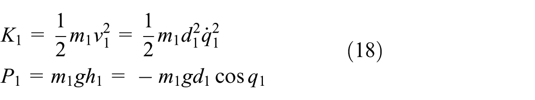
Link 2
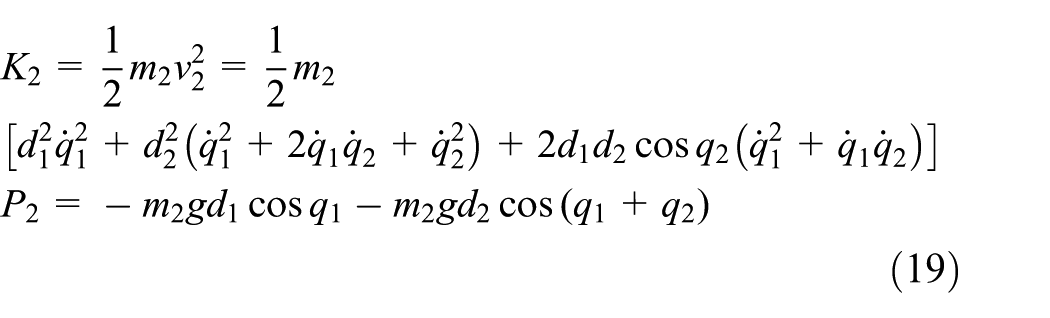
The dynamic equation L = T − P can be calculated through the Lagrangian. Substituting equations (18) and (19) into L = T − P, we can get the joint torque T1 and T2 for each joint of the arm

Rearranging equations (20) and (21), the new matrix of the two links can be got as

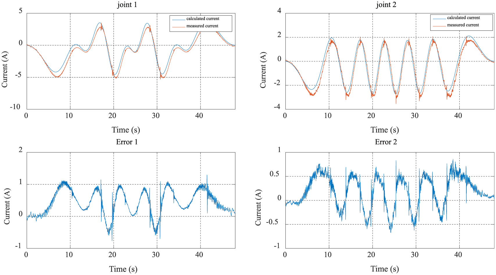
When the system need not consider the friction, the dynamic model can adopt equation (22). We can get the currents calculated by the dynamic model and measured by the encoder of the motor of the same joint. Comparing the currents, we can get the errors of each joint as Figure 3 shows.
As Figure 5 shows, the calculated current by the dynamic model and the measured current by the encoder of the motor are the same but have some big errors. The biggest error of joint 1 is 1.5 A and joint 2 is 1.4 A. Such a big error will have a significant impact on subsequent collision detection.

The calculated current and the measured current (no friction model).
Normally, there are many noises of the mechanical drive system in motion. These will cause low transmission efficiency and cannot get the accuracy dynamic model. According to the previous analysis, this error is caused by the friction mostly. After adding the friction model in the dynamic model (22), the calculated current by the dynamic model and the measured current by the encoder of the motor will become more close as shown in Figure 4.
We can see from the experimental data (shown in Figure 6) that the error of each joint becomes smaller. The biggest error of joint 1 is 1 A and joint 2 is 0.8 A. So, the accuracy of the friction model has the direct bearing on the error.
The calculated current and the measured current (add friction model).
The accuracy of the dynamic model and the friction model has the direct bearing on the setting of the collision current threshold of collision detection algorithm. So, it is important for the collision detection to correct and identify the error.
Sensorless collision detection
In order to get the experimental result of the sensorless collision detection algorithm, this research uses the 2R planar manipulator to conduct the collision detection experiment. The experimental performance and the corresponding results are shown in Figure 7. There is a contrast experiment, one with no collision detection and another one with the collision detection. The experiment uses one paper to collide the arm. Figure 7(a) with no collision detection shows that the paper is broken by the arm. Figure 7(b) with the collision detection shows that the arm stops when it collides with the paper. The data of

Two experiments: (a) no collision detection and (b) collision detection.
On the basis of the collision detection algorithm, when the link collided with the paper, the system will detect the collision and the current peak will exceed the threshold. Then, the arm will stop and move back base on the zero gravity. This experiment aims to show the importance of the collision detection algorithm during the instant of the collision.
Figure 8 shows the

Experimental verification of applicability of sensorless collision detection.
Conclusion
This research proposes a method about sensorless collision detection algorithm. The friction model is introduced into the dynamic model to enhance the accuracy of the algorithm. The observed value of residual error was used to compare with the threshold to detect the collision. The performance of the proposed collision detection method was evaluated using a 2R planar manipulator. The experimental results show that collision can be reliably detected without any extra sensors. Two important conclusions were summarized:
The collision detection algorithm is based on the dynamic model and friction model and no need of extra sensors. Therefore, this method can apply to any industry robot and no need to change the structures of it.
The accuracy of the collision detection algorithm depends most on the model of the dynamic and the friction. So establishing a more precise model for the robot is a most important part of the collaborative robot.
There is much research work to do in the future. This collision detection algorithm is just verified on the two-link robot arm. When the 6-DOF collaborative robot is finished, it has a broader application prospects.
Footnotes
Handling Editor: Fei Chen
Declaration of conflicting interests
The author(s) declared no potential conflicts of interest with respect to the research, authorship, and/or publication of this article.
Funding
The author(s) disclosed receipt of the following financial support for the research, authorship, and/or publication of this article: This work was supported by National Nature Science Foundation of China (No. 51405469).