
Abstract
Tensioning, as a plastic forming process, is the most important and advanced manufacturing process for circular saw blade. Multi-spot pressure tensioning is a new tensioning method that has been proposed and applied in recent years. However, the effects of process parameters of this method on tensioning effect of circular saw blade have not been systematically studied. This study aimed to examine the effects of loading force and spot distribution on tensioning stress field and natural frequencies of multi-spot pressure tensioned circular saw blade systematically. Both of these were calculated by a combination of dynamic/explicit, static/general, and frequency modules of ABAQUS software. An X-ray stress test validated the simulated tensioning stress field. Results show that loading force and spot distribution have effects on tensioning stress field and natural frequencies of circular saw blades with different extents.
Introduction
Circular saw blade is one of the most widely used machining tools. Its cutting quality is greatly affected by its dynamic stability. 1 Li reported that natural frequency and tensioning stress field have the greatest impact on the dynamic stability of circular saw blade. They are the two important performance indicators for tensioned circular saw blade and referred to as the tensioning effect. 2
Multi-spot pressure tensioning process has recently emerged and been applied in the industry. Local plastic deformations are produced in many regions of circular saw blade during the pressing process of spherical head. Loading force and spot distribution can be adjusted accurately and automatically. Li et al. 3 proved the feasibility of this tensioning process based on theoretical analysis and tensioning stress test.
Before the emergence of multi-spot pressure tensioning process, roll tensioning and hammering were the main methods for tensioning of circular saw blade. 4 Partial heating for circular saw blade was also a tensioning method. 5 There is a substantial amount of research about tensioning effect of circular saw blade as shown below.
The vibration properties of a circular saw blade subjected to initial tensioning stresses were determined by Carlin theoretically. 6 An industrial method was proposed by Schajer 7 for testing the tensioning effect. The light gap between the blade surface and the edge of a curved ruler was tested. Lateral stiffness was used by Stakhiev 8 for the optimization of tensioning effect in coordination of tensioning degree with rotation speed. An experimental device was constructed by Schajer et al. 9 for identifying the mode of vibration and controlling saw blade tensioning. A dynamic stability analysis model of a circular saw blade under a thermal load was built and Ishihara et al. studied the dynamic characteristics of the circular saw blade based on a genetic algorithm.10,11 Cristóvão et al. 12 studied the effects of process parameters on natural frequency of roll tensioned circular saw blade based on ABAQUS software. Gospodaric et al. 13 proposed an active electromagnetic system for weakening the vibration of circular saw blade. In summary, harmonic and impulse tests are the main test methods for natural frequencies and vibration modes of circular saw blade. Finite element method is the main analysis method for natural frequencies and vibration modes of circular saw blade.
Szymani and Mote 14 discussed the tensioning stresses of roll tensioned circular saw blade and their effects on stability of circular saw blade. Szymani and Mote 15 reported the tensioning stress field of roll tensioned circular saw blade based on experimental measurements and theoretical analysis. A theoretical model was presented by Schajer and Mote 16 that accurately described the tensioning stress field in a roll tensioned circular saw blade. Schajer and Mote 17 built a mathematical model that allowed for the prediction of optimal tensioning parameters for saw blade. Nicoletti et al. 18 built a finite element model for roll tensioning processes and calculated the tensioning stress field. Heisel et al. 19 examined the effects of roll tensioning parameters on tensioning stress field through ABAQUS software. In summary, X-ray stress test is the main test method for tensioning stress field of circular saw blade. Finite element method is also the main analysis method for tensioning stress field of circular saw blade.
Multi-spot pressure tensioning processes have their own advantages and are widely used in circular saw blade tensioning process.20,21 The loading force and spot distribution are the most important process parameters that influence tensioning effect of circular saw blade. However, there is no related research about this which limits the development and popularity of this tensioning process.
Experimental
Materials
The circular saw blade was made in the Tianjin Forestry Tools Factory (Tianjin, China). The material of circular saw blade was alloy spring steel GB 65Mn. Its hardness, diameter, and thickness were hardness conversion table (HRC) 42, 356 mm, and 2.2 mm, respectively. The center bore diameter of circular saw blade was 30 mm. The spherical pressure head was supplied by the Beijing Forestry University (Beijing, China). The hardness and radius of the spherical pressure head were HRC 60 and 70 mm, respectively.
Methods
Process parameters of multi-spot pressure tensioning process
Loading force and spot distribution are the most important process parameters that have effects on tensioning effect of circular saw blade. Circumferential spot number, radial spot number, and spot radius are the main parameters used to characterize the spot distribution. The loading force was changed from 40 to 85 kN, circumferential spot number was changed from 10 to 16, radial spot number was changed from 1 to 3, and spot radius was changed from 80 to 140 mm.
For facilitating understanding, a schematic diagram is shown in Figure 1. The circumferential spot number was 16 and radial spot number was 3. The radius of spots in the outermost ring was 140 mm, the radius of spots in the middle ring was 110 mm, and the radius of spots in the inner ring was 80 mm. The tooth shape of circular saw blade was not considered in both the experimental and the theoretical analysis. Therefore, circular saw blade was assumed to be a disk and the saw tooth was not drawn in the figure.

Spot distribution of multi-spot pressure tensioning process.
Tensioning effect analysis of circular saw blade based on finite element method
Considering the calculation efficiency and precision comprehensively, the dynamic/explicit module of ABAQUS software (6.10, Dassault SIMULIA, Providence, RI, USA) was chosen to simulate the elastic–plastic loading process of multi-spot pressure tensioning in this article. A simulation similar to a quasi-static loading process was achieved by adjusting the step time. Relevant theories were presented in Li et al. 3
The elastic deformation of spherical pressure heads was ignored. It was modeled as an analytical rigid body. This article belongs to applied basic research and some acceptable assumptions were made for circular saw blade. A linear strengthening elastic–plastic model was chosen as the material model of circular saw blade, with a yield strength of 430 MPa and a strain hardening rate of 1000 MPa. 3 Its elastic modulus, Poisson ratio, and density were set to 210 GPa, 0.3, and 7.8 g/cm3, respectively.
All of the translational degrees of freedom (DOF) at the inner surface of the center hole of the saw blade were restricted. All spherical heads were moved to the surface of the saw blade simultaneously via loading force. Two planes of circular saw blade were pressed by spherical pressure heads simultaneously. The simulation of all local plastic deformations produced simultaneously was assumed to be similar to the simulation of local plastic deformations produced one by one. The coefficient of friction between steels is approximately 0.1–0.15. 22 Therefore, kinetic friction was applied between the spherical head and the circular saw blade; the friction coefficient was set to 0.12. 3
The spherical pressure head was not meshed. The three-dimensional eight-node reduced integral element, C3D8R, was selected for the circular saw blade, as shown in Figure 2. There were 41,472 elements for the circular saw blade. One simulation of all the working conditions in this article was shown in Figure 2 to give readers a clear understanding. The related parameters of Figure 2 were shown in Figure 1.

Finite element model for dynamic stability analysis of circular saw blade.
Using the final stress field of loading process as the initial state of unloading process, the tensioning stress field of circular saw blade after the linear elastic unloading process was obtained by the static/general module of ABAQUS software.
Using the tensioning stress field as the initial state, the frequency module of ABAQUS software calculated the natural frequencies and vibration modes of circular saw blade. The mode shapes of the tensioned circular saw blade were simulated for nodal circle (Nc) of 0 and nodal diameter (Nd) of 1 to approximately 4.
The mode shapes and natural frequencies of any structure can define the structure’s dynamics. The vibration of a circular saw blade can be regarded as the sum of some individual vibration modes. Each individual vibration mode has a specific mode of vibration and is vibrating at a certain frequency, which is called the natural frequency. The mode shapes of circular saw blade are characterized by the number of nodal circles (Nc) and the number of nodal diameters (Nd). Nc represents the number of lines which have radial shape. Nd represents the number of lines which are located on diameters.23,24 The most common vibration modes typically have zero to four nodal diameters and zero nodal circles during woodcutting processes. Natural frequency is an important index to evaluate tensioning effect.
Tensioning stress test for circular saw blade
The calculation accuracy of tensioning stress field is the key point for the finite element model, which can also determine the precision of natural frequency. Therefore, the tensioning stress test was performed to prove the correctness of the finite element model. The tensioning stress field of the tensioned circular saw blade was measured using an X-ray stress meter (Handan Stress Technologies, Handan, China). The tensioning stress test path was shown in Figure 1.
Results and discussion
Validation of the finite element model
The experimental process parameters were shown below. Figure 1 shows the spot distribution, and the loading force of spherical pressure head was set to 40 kN. The transformation of stress can be realized in ABAQUS software. The stresses in the Cartesian coordinate system were converted into stresses in Polar coordinates. The simulation results and stress measurement results are shown in Figures 3 and 4.
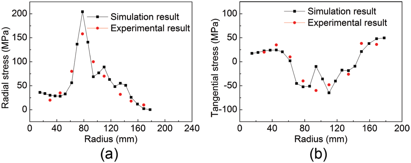
Contrast of tensioning stress between simulation and experimental results: (a) radial stress distribution and (b) tangential stress distribution.

Simulation results of tensioning stress, Chladni patterns, and natural frequency f: (a) stress field of loading process (MPa), (b) tensioning stress field (MPa), (c) mode (Nc = 0, Nd = 0), (d) mode (Nc = 0, Nd = 1), (e) mode (Nc = 0, Nd = 2), (f) mode (Nc = 0, Nd = 3), and (g) mode (Nc = 0, Nd = 4).
As shown in Figure 3, the radial stresses in most regions of the multi-spot pressure tensioned circular saw blades are tensile. It is favorable for the improvement of the dynamic characteristic of a circular saw blade. It is a difference between multi-spot pressure tensioning and roll tensioning process. Circular saw blade obtains radial compressive tensioning stress during roll tensioning process, which makes it easy to lose stability and buckle into a “dish” shape. In addition, the tangential tensile tensioning stress in the edge of circular saw blade increases with radius. The tangential tensile tensioning stress can compensate for the tangential compressive thermal stress and improve the stability of circular saw blade under working conditions.
Table 1 shows the natural frequency of a circular saw blade in its initial state. The natural frequency of Nc = 0 and Nd = 0 is slightly more than that of Nc = 0 and Nd = 1. Natural frequency increases with nodal diameter when Nd ≥ 1. The calculation results agree with previous research results of other scientists,2,16,19 which also prove the correctness of the modal analysis model in this article.
Natural frequency of a circular saw blade in its initial state.

As shown in Figure 4, for static circular saw blade, there is only one vibration mode when zero nodal diameters are present. Two similar mode shapes are shown, and similar frequencies are found for non-zero nodal diameters. The calculation results agree with previous research results of other scientists. 2 As shown in Figure 4 and Table 1, compared with the un-tensioned circular saw blade, natural frequency of Nc = 0 and Nd = 0 of a circular saw blade tensioned by multi-spot pressure is slightly reduced, natural frequency of Nc = 0 and Nd = 1 of circular saw blade tensioned by multi-spot pressure is almost unchanged, and natural frequencies of Nc = 0 and Nd ≥ 2 of circular saw blade tensioned by multi-spot pressure are greatly increased. The effect of multi-spot pressure tensioning process on natural frequencies of circular saw blade is the same as roll tensioning process. The simulation results show that multi-spot pressure tensioning process can improve the dynamic characteristic of circular saw blade.
Effect of loading force on tensioning effect of circular saw blades
The working conditions for simulation in this part were shown below. Loading forces of the spherical pressure head were 40, 55, 70, and 85 kN. The spot distribution was unchanged, as shown in Figure 1.
Under different loading forces, tensioning stress distribution of circular saw blade is shown in Figure 5, dent depth and natural frequency of circular saw blade are shown in Figures 6 and 7, respectively. Dent depth is increased with loading force because plastic deformation is intensified due to increase of loading force.

Tensioning stress of circular saw blade with different loading forces: (a) radial stress distribution and (b) tangential stress distribution.

Dent depth with different loading forces.
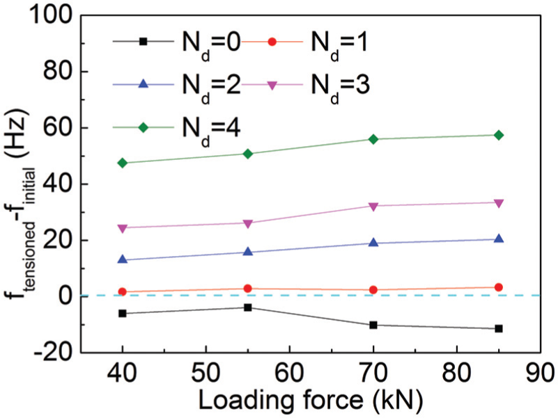
Natural frequency difference with different loading forces.
As shown in Figure 5, radial tensile stress in the middle of circular saw blade and tangential tensile stress at the outer edge of circular saw blade are all increased with loading force because plastic deformation is intensified with loading force. It is beneficial for circular saw blade to offset the undesirable thermal stress produced at the outer edge when circular saw blade is at work. From the perspective of offset thermal stress, it is beneficial to increase loading force.
The generation of radial tensile stress and tangential tensile stress is also helpful for the dynamic characteristics improvement of circular saw blade. As shown in Figure 7, ftensioned − finitial represents the natural frequency difference between tensioned and un-tensioned circular saw blade. When loading force changes from 40 to 85 kN, compared with the un-tensioned circular saw blade, natural frequency of Nd = 0 is slightly reduced, natural frequency of Nd = 1 is almost unchanged, and natural frequencies of Nd ≥ 2 are substantially increased.
By comparing these circular saw blades tensioned by different loading forces, natural frequencies of Nd ≥ 2 are increased with loading force because the radial tensile stress and tangential tensile stress are all increased with loading force. However, the increased amount of natural frequencies for Nd ≥ 2 with loading force is limited because the undesirable tangential compressive stress produced in the middle of circular saw blade is also increased significantly with loading force, as shown in Figure 5.
Effect of circumferential spot number on tensioning effect of circular saw blades
The working conditions for simulation in this part were shown below. Loading force of spherical pressure head was 40 kN. Circumferential spot numbers were 10, 12, 14, and 16. Radial spot number was 3. Radius of spots was 140, 110, and 80 mm.
Under different circumferential spot numbers, tensioning stress distribution of circular saw blade is shown in Figure 8 and natural frequency of circular saw blade is shown in Figure 9.
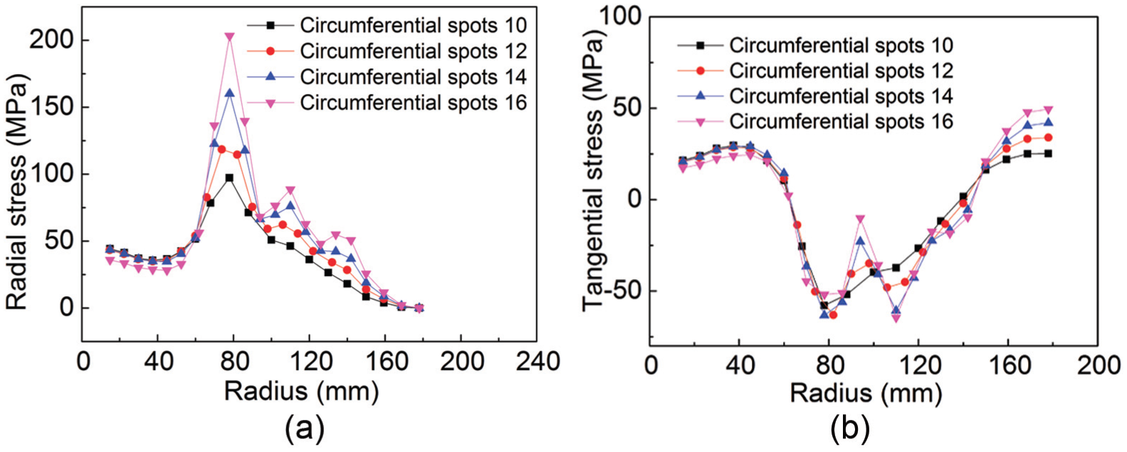
Tensioning stress of circular saw blade with different circumferential spot numbers: (a) radial stress distribution and (b) tangential stress distribution.

Natural frequency difference with circumferential spot number.
As shown in Figure 8, radial tensile stress in the middle of circular saw blade and tangential tensile stress at the edge of circular saw blade are all increased with circumferential spot number because the number of local plastic deformation zone is increased and tensile stress is increased by superpositioning. It is beneficial for circular saw blade to offset the undesirable thermal stress produced at the outer edge when circular saw blade is at work. It is also helpful for the dynamic characteristics improvement of circular saw blade. As shown in Figure 9, natural frequencies of Nd ≥ 2 are increased with circumferential spot number because tensioning stresses are increased with circumferential spot number. The increased amount of natural frequencies for Nd ≥ 2 with circumferential spot number is more substantial than that with loading force because the increase of undesirable tangential compressive stress produced in the middle of circular saw blade with circumferential spot number is less obvious than that with loading force, as shown in Figure 8.
Effect of radial spot number on tensioning effect of circular saw blades
The working conditions for simulation in this part were shown below. Loading force of the spherical pressure head was 40 kN. Circumferential spot number was 16. Radial spot number was 1, 2, and 3. Radius of spots was 140 mm when radial spot number was 1. Radius of spots was 140 and 110 mm when radial spot number was 2. Radius of spots was 140, 110, and 80 mm when radial spot number was 3.
Under different radial spot numbers, tensioning stress distribution of circular saw blade is shown in Figure 10 and natural frequency of circular saw blade is shown in Figure 11.

Tensioning stress of circular saw blade with different radial spot numbers: (a) radial stress distribution and (b) tangential stress distribution.

Natural frequency of circular saw blade with different radial spot numbers.
As shown in Figure 10, radial tensile stress region and tangential compressive stress region in the middle ring of the circular saw blade are all extended with radial spot number. The tangential tensile stress region at the outer edge of circular saw blade is extended and the value of tangential tensile stress is increased with radial spot number.
As shown in Figure 11, compared with the un-tensioned circular saw blade, the dynamic characteristic of circular saw blade is not improved when radial spot number is 1 or 2. The first reason is that the undesirable tangential compressive stress region is closer to the outer edge of circular saw blade. The second reason is that the beneficial tangential tensile stress region at the outer edge of circular saw blade is relatively small. The third reason is that the beneficial tangential tensile stress at the outer edge of circular saw blade and radial tensile stress in the middle of circular saw blade are relatively small. When radial spot number is 3, the dynamic characteristic of circular saw blade is greatly improved.
As shown in Figure 11, natural frequencies of Nd ≥ 2 are remarkably increased with radial spot number due to the tensile stress region and its increased value. The dynamic characteristics of circular saw blade are improved when radial spot number is increased in a reasonable range. When radial spot number is set to 3, an ideal natural frequency and tensioning stress field are obtained.
Effect of spot radius on tensioning effect of circular saw blades
The working conditions for simulation in this part were shown below. Loading force of spherical pressure head was 40 kN. Circumferential spot number was 16. Radial spot number was 1. Spot radius was 80, 100, 120, and 140 mm.
Under different radius of spots, tensioning stress distribution of circular saw blade is shown in Figure 12 and natural frequency of circular saw blade is shown in Figure 13.

Tensioning stress of circular saw blade with different radius of spots: (a) radial stress distribution and (b) tangential stress distribution.

Natural frequency of circular saw blade with different radius of spots.
As shown in Figure 12, the radial tensile stress region and tangential compressive stress region move toward the outer edge of circular saw blade with spot radius. The tangential tensile stress region at the outer edge of circular saw blade is reduced. Meanwhile, the value of tangential tensile stress at the outer edge of circular saw blade is not large enough to offset the adverse thermal stress when radial spot number is only 1.
When the tangential compressive stress region moves toward the outer edge of circular saw blade gradually with spot radius, the positive influence of tangential tensile stress at the outer edge on dynamic characteristics of circular saw blade is weakened, the dynamic characteristics of circular saw blade become bad and circular saw blade is more easy to lose stability at work. As shown in Figure 13, the simulation results also prove the above inference.
Meanwhile, when pressure spots move gradually toward the center of circular saw blade, natural frequency for Nd = 0 visibly decreases. When the tangential compressive stress region moves toward the center of circular saw blade, natural frequency for Nd = 0 decreases and an over-tensioning phenomenon of circular saw blades is likely to appear.
Conclusion
Based on tensioning effect analysis of circular saw blades after multi-spot pressure tensioning process, natural frequencies for nodal diameters Nd ≥ 2 are increased and an ideal tensioning stress field is obtained by setting reasonable process parameters for multi-spot pressure tensioning. Multi-spot pressure tensioning process has an obvious effect and is advantageous for the dynamic characteristics improvement of circular saw blade.
Both the loading force and the spot distribution have effects on the tensioning stress field with different extents. By setting reasonable process parameters, the tensioning stress field is beneficial for compensating the negative thermal stress produced during the cutting process.
Both the loading force and the spot distribution affect the natural frequencies of circular saw blade to different extents. The dynamic characteristic of circular saw blade is improved with loading force, circumferential spot number, and radial spot number to a different degree. The dynamic characteristics improvement of circular saw blades is weakened with spot radius.
Footnotes
Handling Editor: Hiroshi Noguchi
Declaration of conflicting interests
The author(s) declared no potential conflicts of interest with respect to the research, authorship, and/or publication of this article.
Funding
The author(s) disclosed receipt of the following financial support for the research, authorship, and/or publication of this article: This work was supported by the National Natural Science Foundation of China (No. 31600458) and the Fundamental Research Funds for the Central Non-profit Research Institution of CAF (No. CAFYBB2017SY039).