
Abstract
Degradation of dissimilar metal welds in the piping systems of power plants is recognized as a significant ageing factor. Hence, close scientific attention is paid to various degradation mechanisms concerned with dissimilar metal welds, as well as to welding metallurgy. However, the process of dissimilar metal weld refurbishment consisting of the weld groove machining and subsequent repair welding is based on obsolete methods. Particularly, the machining stage has to rely on conventional portable machining or, more often, on manual grinding. Neither of these methods is adequate, especially when it comes to the special environment of the nuclear power plants. In this article, a novel design of an automatic orbital milling system intended for machining degraded welds in piping systems is presented. The system incorporates an orbital milling head designed to enable machining within the limited space, combined with a microcontroller-based control system providing full control over the geometry of the weld groove. Thus, the degraded dissimilar metal weld is removed, and simultaneously, the weld groove of desired geometry is prepared rapidly and flexibly, without the need for customized profile cutters, being the main contribution of the proposed design. The system prototype was verified by implementation in the Bohunice V2 nuclear power plant.
Keywords
Introduction
Safe and reliable operation of power systems is of high priority, especially when it comes to nuclear power plants (NPPs). Hence, significant scientific attention is paid to the mechanisms that accelerate their ageing. The substantial role of various corrosion mechanisms in ageing of NPPs has long been known. According to Trolle, 1 there are two major corrosion-related problem areas in nuclear power systems: in the case of boiling water reactor (BWR) systems, inter-granular stress corrosion cracking (SCC) appears in the weld heat–affected zones of the piping; whereas, pressurized water reactor (PWR) systems suffer from many different forms of corrosion occurring in the zone of steam generators. The phenomenon of SCC of dissimilar metal welds (DMWs) has been examined by Brust and Scott, 2 Busby et al. 3 and Mohanty et al., 4 among other authors, and it is recognized as a key ageing factor in the NPPs. It is a well-known fact that the severity of corrosion-induced problems grows as the age of NPP approaches its planned service life. NPPs begin to deteriorate after roughly 10 years of operation, as shown by experience in the power industry. 5 Currently, the age of most operational nuclear reactors worldwide is between 25 and 40 years. 6 This implies that the problem of ageing and maintenance of the critical components is becoming more than relevant. A lot of scientific effort has been made to find suitable solutions: various research tasks have been focused on SCC of DMWs from the standpoint of material mechanics, metallurgy and welding technology, in order to provide a prevention against degradation of the weld joints. However, there are many NPPs that already encountered the troubles with critically flawed weld joints in their piping systems. For this reason, it is clear that the development of advanced weld refurbishment methods is inevitable.
Fundamentally, the procedure of a DMW refurbishment consists of the weld excavation and subsequent repair welding. According to Emmerson 7 and Latifi, 8 advanced methods of orbital welding have been known for a long time. These welding techniques are capable of extending the joint life by more than 20 years. 9 Owing to automation of the welding process, not only repeatable results of excellent quality can be achieved but also the negative impact of welding on operator’s health is minimised. 8 Nonetheless, the situation is different in the field of on-site machining: no comparably progressive methods of flawed weld excavation can be, to present date, observed. Hence, the primary goal of our work was to develop a milling system which would satisfy the requirements imposed by the refurbishment method and which would respect the set of restrictions imposed by the specific environment of NPPs. Development of the machining system was motivated by the need for refurbishment of critically flawed DMWs in the steam generator zone of Bohunice V2 NPP. The purpose of this article is to introduce the design of the proposed milling system and to present its application in the Bohunice V2 NPP.
Let us sum up the state-of-the-art in the field of conventional on-site machining of pipes. The portable machine tools available today fall into two categories. The first one is formed by the carriage-type milling machines for pipe severing and bevelling. These machines utilize either a cylindrical mill or a disc mill as a cutting tool, and the bevel geometry is defined by the cutter profile. Cutting is performed by the carriage being moved around the pipe, while the depth of the cut is pre-set and fixed so that the cutter penetrates the entire thickness of the pipe wall. Chains are used to fasten the carriage on the pipe, as well as to guide it. The patents by Mitchell, 10 Vanderpol and Larson 11 and Levey, 12 among other, relate to this category of the milling machines. Probably, the best known machine from this category is the Trav-L-Cutter designed by EH Wachs. The second category comprises the portable turning machines that are often referred to as clamshell or split-frame lathes, according to patent documents by Swiatowy and Polifka, 13 Hall and Robert 14 and Wokan et al., 15 among others. These machines which are also intended for pipe severing and bevelling use a different concept: a rigid circular frame bears a rotary ring which carries two sliders placed in opposed position. The radial motion of the tool bits fixed in the sliders and the orbital motion of the rotary ring are coupled by a fixed transmission ratio, thus applying the principle of groove turning. The shape of the groove or bevel is, again, defined by the tool profile. The circular frame typically allows for splitting into two halves, so that the machine can be attached to a continuous stretch of piping. In addition to machining, the contactless cutting technologies such as plasma, laser and waterjet cutting should also be mentioned. Generally, these technologies occupy an important place in manufacturing, and they are also used for pipe severing and bevelling. However, these cutting methods only allow for producing simple surfaces, and at the same time, the cut necessarily has to penetrate the entire thickness of the material. For these reasons, they are not suitable for the purpose of the flawed weld excavation.
The machines and methods mentioned in the previous paragraph are well suited for the on-site severing and bevelling of pipes. Nevertheless, the requirements on effective weld refurbishment within the restrictive conditions of NPPs are beyond their capabilities due to three reasons: first of all, the desired groove profile is generally subject to changes from case to case depending on factors such as the original geometry of the weld, level of degradation, distribution of flaws and welding method to be used. For this reason, there is an essential requirement for flexibility in the shape and dimensions of the weld groove without the need for customized cutting tools. In addition, the machining system should be capable of widening the weld groove operatively based on possible detection of the residual flaws after initial machining being finished. Second, in order to guarantee a flawless weld root, the tolerance of the root lip thickness is significantly tight. 7 Since the shape deviations of the pipes such as roundness and concentricity are usually much greater than this tolerance, the machining system should compensate for them. Finally, not only the groove profile geometry but also the length and position of the circumferential section of the groove should be controllable. The reason is that it is necessary to preserve the original relative position of the joined pipes without the need for additional fixtures intended for holding the pipes in the correct position during welding. To satisfy this demand the two-stage refurbishment procedure might be utilized: simply said, one half of the weld girth is repaired first and the rest is processed afterwards. Along with the said demands placed on the DMW refurbishment, the environment of NPPs also imposes a set of restrictions on the refurbishment process. First, cramped space around the pipes with problematic DMWs often constitutes an essential restriction. Next, the flawed welds are likely to occur within the primary or secondary circuit of the NPPs, where handling the liquid and particulate materials is strictly regulated and the application of the liquid coolants during machining is mostly forbidden due to the presence of the ionizing radiation. Likewise, the machining system that is used must prevent any contaminated dust particles from entering its internals. 16 Last but not least, increased temperature in the work environment might also impose restrictions on the refurbishment procedure.
The said requirements and restrictions concerned with the environment of NPPs constitute the reason why application of the conventional portable machine tools as well as manual grinding in the procedure of DMW refurbishment is often impossible. Our design of the orbital machining system which was developed to overcome this deficiency is presented in the following sections.
Mechanical system design
It is well-known that the technology of numerically controlled high-speed milling constitutes a powerful way of machining generic surfaces. An essential advantage of this method is the fact that shape and dimensions of the machined surface are defined by a program instead of a tool profile. Thus, various shapes can be achieved in a rapid and inexpensive fashion using only the standard cutting tools such as flat or rounded end mills and ball nose cutters. Moreover, any alteration of the machined shape is reflected by editing the program, but it has no influence on the mechanical setup. Hence, this approach yields remarkable flexibility to the machining process. For these benefits, we applied the principle of three-directional (3D) numerically controlled milling to the problem of excavation of the flawed DMWs in piping systems. Our numerically controlled orbital milling system was conceived to adopt a 3D face milling strategy utilizing standard carbide end mills as cutting tools.
From the physical point of view, the system consists of the three main units: milling head, distribution box and a man–machine interface (MMI). These units, which are described in the following subsections, are depicted in Figure 1. Figure shows the milling system prototype dedicated for the piping up to 150 mm in diameter and wall thickness up to 16 mm. The most important technical parameters of the prototype are presented in Table 1.

Main parts of the machining system: (1) milling head, (2) distribution box and (3) man–machine interface.
Technical parameters.

Milling head
The milling head, which forms the structural part of the system, was developed to provide necessary rigidity as well as the desired kinematic structure. The milling head assembly consists of four main bodies which are, according to Figure 2, the base (A), the axial support (B), the tangential support (C) and the headstock (D). These components are bound together by two prismatic guides and one circular guide, forming a mechanism with a serial kinematic structure shown in Figure 3.

Main parts of the machining head: (A) base, (B) axial support, (C) radial support, (D) headstock and orientation of the feed axes.

Block diagram representing the serial kinematic structure of the milling head.
As apparent from Figures 1 and 2, the milling head is attached to the circular piping, so that its cylindrical coordinate system is aligned with the cylindrical coordinates of the pipe. Thus, the tool can be positioned in the axial, tangential and radial direction with respect to the pipe or X, A and Z axes, respectively. Because of adoption of the face milling strategy, the spindle axis is collinear with the radial axis (Z axis). The main dimensions of the prototype are shown in Figure 4.
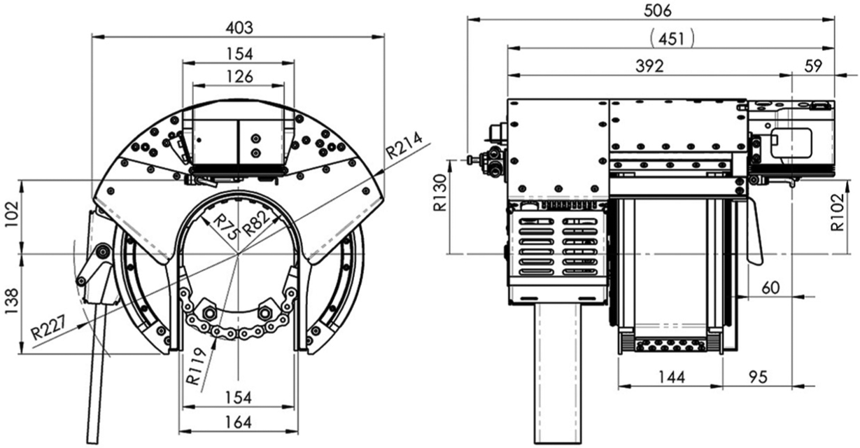
Essential dimensions of the prototype of milling head.
All the three feed axes are equipped with digitally controlled stepping drives in order to achieve the highest torque-to-size ratio of the electric motors. This is important due to desired compactness of the milling head. Thus, sufficient low-speed performance is achieved using very compact electric motors. However, the high-speed performance of such a drive system is decreased. The three-phase stepping drives were preferred over the two-phase alternatives for their advantages such as more favourable speed–torque characteristics and lower susceptibility to resonance issues. The YAKO YK366A stepping motor was used for the X axis while the YAKO YK368A motors were used for the A and Z axes. These stepping motors provide the nominal continuous torque of 0.9 and 1.5 N m, respectively. All the feed axes are equipped with the incremental encoders Megatron ENI22 B with 1024 pulses per revolution and transistor–transistor logic (TTL) output, providing position feedback to the control system. The spindle is driven by the compact high-torque brush-less DC (BLDC) motor AXI 5330/18. The torque of the BLDC motor is transferred to the spindle using a belt drive with micro-V profile. The end mill is attached to the spindle by means of a clamping collet.
Distribution box and MMI
The distribution box shown in Figure 1 encompasses the power electronics, control electronics and standard electrical safety devices. There are two 1500-W parallel-connected Mean Well SPV-1500 switching power supplies installed for powering the spindle, and one 350-W Mean Well SE-350 switching power supply intended for powering the stepping drives of the power feeds. A Jeti Mezon 75 BLDC motor driver is used for driving the spindle, and three YKB3606MA stepper motor drivers are used for driving the feed axes. All motor drivers are connected to a custom-designed controller board.
At the heart of the controller board is an 8-bit ATMEL ATmega2560-16AU microcontroller unit (MCU) being the main computing unit of the numerical control (NC) system. The 8-bit MCU technology has been selected due to its good performance and simple design, which brings robustness needed in environments exposed to ionizing radiation, among other benefits. 17
The MMI of the machining system shown in Figure 1 is designed as a handheld device. It enables the operator to interact with the machine by controlling functions and monitoring information displayed on the screen. The MMI comprises an ATMEL ATmega32 8-bit MCU, which is connected to the main controller board via an asynchronous serial communication interface.
Control system design
Essential characteristics
From the hardware point of view, the control system of the proposed orbital milling system consists of three main units: computer numerical control (CNC) unit, drive unit and machine tool itself. The hardware structure of the system is presented in the lower part of Figure 5.

Architecture of the control system of the orbital milling system.
From the software point of view, the main components of the control system shown in the upper part of Figure 5 are as follows: (1) software dedicated for the man–machine controller (MMC), (2) software for the numerical control kernel (NCK) and programmable logic controller (PLC) and (3) the motor driver software. The first two parts of the software were custom-designed, whereas the motor driver software was purchased with the drivers. The NCK/PLC unit constitutes the core part of the control system. This software serves five key functions: path generation, deviation compensation, logic control, acceleration/deceleration (A/D) control and position control. From these functions, the first two are non-real-time functions, whereas the last three functions have to run in real time.
The main difference between the structure of our control system and the general architecture of CNC control systems according to Suh et al. 18 lies in the following two factors. First, the way the information on toolpaths is stored in the memory is different. The standard G-code (RS-274), which is, as a general rule, generated by the external post-processor, is not used in our case since the toolpaths are not imported to the system. Instead, toolpaths are pre-calculated by the path generator module, based on the set of parameters entered to the system by the operator. Thus, the part program interpreter is not integrated in the control system since it is substituted by the path generator module. Second, the control system does not utilize a real-time interpolator as it is not necessary for the intended application, where the point-to-point motion control is adequate. Nonetheless, certain kind of interpolation is integrated in the control system: it is used for the adaptation of toolpath to the shape deviations of the pipe being machined, so that the system compensates for these deviations. All the functions of NCK/PLC unit are explained in the following subsections.
The CNC control system brings flexibility to the geometry of the groove, only using common standard tools: a flat end mill is employed in the roughing stage, whereas a ball nose cutter or rounded end mill is used to accomplish the smooth finish cut. These types of standard cutting tools are applicable regardless of the geometry of the groove to be machined. Figure 6 shows an example of the weld groove for the DMW repair in the piping system of a steam generator. It is worth emphasizing that the milling system provides full control over the length and position of the circumferential groove section. This allows for performing the refurbishment in the aforementioned two-stage manner. Owing to this technique, the original relative position of the joined pipes can be secured with no need of fixtures.

Example of the weld groove needed in the case of degraded DMW repair: the groove is defined by the set of parameters
Along with flexibility, the control system also enables the operator to adjust the balance between the accuracy of the machined profile and time saving. For instance, it is possible to choose whether to perform full machining including the finishing stage to prepare a smooth surface suitable for non-destructive testing or to omit the finish machining.
Path generator
Generally, a part program interpreter constitutes an important part of a CNC system. However, this feature was not included in our control system, since, in the application of on-site weld groove machining, it does not bring benefit to interpret the part programs generated by the external post-processors. Instead of the function of part program interpretation, the control system should offer a capability to generate the toolpaths operatively, based on the desired geometry of the groove. The latter is the role of the path generator, which transforms the input information to the set of points fully defining the toolpaths. The input information is entered to the system as a set of parameters that can be divided into two groups: (1) geometric parameters defining the shape and dimensions of the groove and (2) technological parameters determining the milling strategy. After entering the parameters to the system via MMI, the points determining the toolpaths are calculated and saved to the memory. An example of a set of parameters defining the groove geometry is shown in Figure 6.
Deviation compensation
The control system allows for a movement synchronization of the axes, so that non-circular grooves can be machined as well. This feature is intended to compensate shape deviations, which are always present on real pipes. Initially, the data on shape deviations are acquired by measuring the pipe profile at four or more locations along its circumference. This step is carried out after the milling head is attached to the pipeline by touching the pipe surface using the tool clamped in the spindle. The number and distribution of locations at which the profile is measured affect accuracy of the deviation compensation. Hence, an increased number of measurement locations improves the compensation accuracy. The measurements (corrections) taken at the selected points are then interpolated in the main computing unit using the cubic spline interpolation. Thus, the actual surface of the pipe can be traced by the tool reference point when the deviation compensation is activated.
The method of cubic spline interpolation was implemented in order to achieve the best possible approximation of the pipe surface with a low number of measurements, which is the main advantage of this interpolation method. Generally, it is possible to use as little as four evenly spaced measurement locations to generate a sufficient approximation. However, higher number of points increases the accuracy of approximation. Another advantage of the cubic spline interpolation is that the interpolant is a curve having continuous first and second derivatives. Thus, no requirement for a step change in the velocity and acceleration is introduced to the motion control by the interpolant being superposed to the nominal toolpaths. This is a beneficial property, since, from the mechanical point of view, the feasibility of tracking the toolpaths is not violated by the deviation compensator. It is worth noting that the interpolation is not performed in real time. Instead, the interpolant is pre-calculated prior to machining and it is superposed to the nominal toolpaths whenever the compensation is enabled. The real-time synchronization of the movements in tangential axis (A) and radial axis (Z) is based on the master–slave principle, where the radial axis is subordinated to the tangential axis.
As it was already mentioned, narrow tolerance of the root lip thickness is an essential demand for accomplishing a high-quality weld. Deviation compensation was introduced to the control system in order to solve this problem in an effective way: owing to this function, the toolpaths can be flexibly adapted to inaccurate surfaces. Moreover, it makes no difference if the inner surface of the pipe is taken as a reference instead of the outer one. The dissimilarity lies only in the way the deviations are measured.
Operation modes
The machining system may be operated in the two modes: manual mode and automatic mode. In the manual mode, the position commands are directly entered to the system by the operator using the built-in manual pulse generator of the MMI. The motion controller then moves the machine axes to the position set by the operator. In automatic mode, the movements are carried out automatically following the pre-calculated toolpaths. The deviation compensator can be enabled regardless of the actual operation mode being used.
In general, the process of weld groove machining consists of three stages: roughing, widening and finishing. Toolpaths are generated for every stage separately, thus enabling the operator to decide which stage to perform and which to omit based on the demands pertaining to the particular refurbishment. An advantage of such a strategy is the possibility of selection between machining productivity and accuracy. Smoothly machined surfaces are necessary particularly when the capillary tests or other non-destructive tests for the residual cracks are necessary. Nevertheless, this may not always be required: in such a case, the finishing phase of machining can be completely omitted, thus saving a significant amount of time. The typical results of both the roughing and finishing stage of machining are shown in Figure 7, where the difference between surface quality can be noticed.

Detail of the welding grooves machined in automatic mode during the phase of prototype testing; left: groove after roughing stage of machining; right: completed groove after finishing and attaching the consumable insert.
Deployment of the machining system
This section is focused on the practical application of the automatic machining system in the Bohunice V2 NPP which among many other NPPs worldwide encountered problems with degraded DMWs in the piping systems. Bohunice V2 NPP, which is located in the western Slovakia, operates two PWR units of the VVER 440/213 type. Both units were commissioned within 1984–1985. The problems with degradation of DMWs have gradually been escalating; hence, some partial repairs have been carried out. Nevertheless, the number of repetitions of these partial repairs is limited by safety regulations. Thus, further operation of the units required a complete refurbishment of the flawed DMWs.
However, the necessary refurbishment of the flawed DMWs was obstructed by several factors. First of all, the problematic welds were situated in a severely cramped space. The limits of the cylindrical working envelope of the milling head were established to ϕ440 mm × 550 mm as shown in Figure 8. Next, the problematic joints were located in the steam generator zone, where ionizing radiation is present, as well as increased temperature. Hence, usage of the liquid coolants during machining was not allowed due to decontamination issues: liquid cooling had to be partially substituted by a compressed air cooling. Moreover, the machine internals had to be protected against chips and dust due to the risk of contamination. Therefore, compressed air was utilized for generating overpressure in the machine internals.
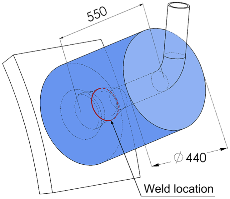
Cylinder representing the working envelope limitation of the machining head attached to the pipe with a problematic weld.
Along with these constraints, there was a set of requirements imposed on the refurbishment. First, the weld groove was intended for the orbital tungsten inert gas (TIG) welding which implied that an accurate groove was required. Second, preservation of the relative position of pipes during welding, free of auxiliary fixtures, was demanded. Next, the residual cracks, possibly remaining in the material after initial machining, had to be detected and operatively removed. Hence, smooth walls of the machined groove were necessary due to subsequent non-destructive testing. Furthermore, the machined groove had to fulfil requirements given by the welding technology itself. Namely, the groove profile was defined by the prescribed geometry which had to be met. Last but not least, in order to guarantee the required quality of the weld root, shape deviations of the pipe, such as eccentricity of the inner surface with respect to the outer surface and roundness had to be taken into account: the machined groove had to be adapted to the actual shape of the pipe profile.
After the prototype of the machining system was completed, a series of tests were carried out on a mock-up. When all the necessary tests were successful, training of the team of technicians from the Bohunice V2 NPP was conducted. After that, the machining system was applied within the refurbishment of the two DMWs in Bohunice V2 NPP. This is documented in the photographs in Figure 9. The most important technological parameters characterizing the machining phase of refurbishment are presented in Table 2. It is worth noting that the welding groove had to be widened in both cases due to detection of cracks which remained in the groove walls after the initial machining was completed. The system of deviation compensation was utilized, which contributed to the good quality of the weld roots. This was confirmed by the results of the final non-destructive tests; however, the evaluation of the weld quality is not within the scope of this article. In the result, the two critically degraded DMWs in the steam generator zone were successfully refurbished in April 2016.

Deployment of the machining system in the Bohunice V2 NPP: (a) machining head mounted on the pipe during the roughing stage and (b) detail of the headstock during roughing of the half-girth weld groove.
Machining parameters in Bohunice V2 NPP.

NPP: nuclear power plant; DMW: dissimilar metal weld.
Conclusion
The goal of our work was to develop a portable milling system intended for excavation of the degraded welds in the piping systems of NPPs and preparation of the weld grooves of prescribed geometry for the repair welding. The system had to be designed to satisfy a set of requirements as well as to respect the restrictions imposed by the specific environment of the NPPs. The development was motivated by the necessity of refurbishment of the critically degraded DMWs in the Bohunice V2 NPP. In this article, the results of our work are presented: the design of a novel, numerically controlled orbital milling system and its successful application in the Bohunice V2 NPP.
A compact three-axis orbital milling system with numerical motion control was designed to allow for machining weld grooves with generic shapes within the restrictive conditions of NPPs. Owing to the microcontroller-based control system providing full control over the weld groove geometry, a weld groove of virtually any shape can be flexibly and accurately machined without the need for customized cutting tools. Moreover, the integrated function of deviation compensation enables to achieve the high-quality weld roots even on significantly inaccurate pipes. These properties pose the key advantages making the presented machining system unique compared to the conventional portable machine tools available today. The application of the machining system may lead not only to lower costs, higher quality and better productivity of the on-site refurbishment of flawed welds but also to decreased exposition of the human operators to the harmful factors of the work environment, such as ionizing radiation, increased temperature, noise and vibrations and contaminated air. These benefits are especially appreciated in the specific environment of NPPs; however, the milling system might open up new possibilities also in different areas, such as petrochemical or food industry where piping systems play an essential role.
The capabilities of the system were first verified during the mock-up tests. After finishing the tests, the system was deployed in the Bohunice V2 NPP during refurbishment of the critically degraded DMWs in the steam generators zone. Refurbishment of the total two DMWs located on the emergency inlet piping of the steam generators was successfully carried out during the scheduled power-down of the steam generators in April 2016. Deployment of the milling system in the Bohunice V2 NPP verified the system functionality and thus it is considered to be the principal result of our work. Practical deployment has shown that despite automation of the machining itself, there is still a source of inaccuracy and downtime in the machining stage of refurbishment due to manual operations, such as deviation measurement, axis referencing and milling head re-clamping. For this reason, there is a need for further development towards an adaptive refurbishment system involving such functions as automated deviation measurement, self-diagnostics and tool diagnostics. In order to increase the overall productivity of the system, further development may also focus on automation of the tool change as well as the elimination of the milling head re-clamping during the whole procedure of the DMW refurbishment.
Footnotes
Acknowledgements
The authors acknowledge the support of the Faculty of Mechanical Engineering, Slovak University of Technology in Bratislava. The authors also acknowledge the contribution of the Welding Research Institute – Industrial Institute of SR and the Bohunice V2 Nuclear Power Plant for their support.
Handling Editor: Kuei Hu Chang
Declaration of conflicting interests
The author(s) declared no potential conflicts of interest with respect to the research, authorship, and/or publication of this article.
Funding
The author(s) disclosed receipt of the following financial support for the research, authorship, and/or publication of this article: This work was supported by the Scientific Grant Agency VEGA of the Ministry of Education of Slovak Republic (grant numbers: 1/0144/15, 1/0317/17) and the Scientific Grant Agency KEGA (grant number: 027STU-4/2017).