
Abstract
A novel roll-channel attitude control scheme using a combination of single-gimbal control moment gyros and a reaction control system is proposed, providing sufficient control torque during the whole reentry process. A scissored-pair configuration is applied to the single-gimbal control moment gyros, which guarantees control torque exclusively along the roll axis and avoids internal singularity. A sliding-mode attitude controller is proposed to meet the requirements of roll-channel attitude stability and disturbance rejection. To obtain an optimal allocation of the commanded torque to the single-gimbal control moment gyros and the reaction control system, an allocation method based on fuzzy reasoning is proposed. To render the design and validation of the control scheme close to reality, the responsiveness of the single-gimbal control moment gyro is considered, and the discrete and delay properties of the reaction control system are included. The steering logic of the single-gimbal control moment gyro and the modulator of the reaction control system are designed, respectively. Numerical simulation is performed to verify the proposed control scheme. Moreover, a hardware-in-the-loop simulation system based on an air-bearing test bed is developed to conduct experiments for convincingly validating the proposed attitude control method. The feasibility and good performance of the proposed control scheme are verified by the results of the numerical simulation and the experiment.
Keywords
Introduction
Attitude control is of great significance to a reentry vehicle as it is used to implement the attitude stabilization and realize the attitude commands generated by the onboard guidance system. However, this is a challenging task for reentry vehicles because the attitude dynamics exhibits characteristics of high nonlinearities, strong couplings, and uncertainties and disturbances in the complex reentry environment. 1 To address these difficulties, extensive studies have focused on the attitude control of reentry vehicles.1–8 To realize these attitude control methods, attention should be paid to the attitude control effectors. Control effectors of reentry vehicles generally consist of aerodynamic surfaces,2,4–6 moving mass,8–11 and reaction control system (RCS).2,4,6,7 Aerodynamic surfaces are the mainstream attitude actuators of reentry vehicles. However, the aerodynamic heating during the reentry process may be too high to make the aerodynamic surfaces ineffective. 12 Moreover, the low dynamic pressure at the initial stage of the reentry can disable the aerodynamic surfaces. 4 Moving-mass control can address the problem of ablation as the mechanism is isolated from the harsh outer environment. 12 However, when the reentry vehicle is at a high altitude where the aerodynamic force and torque are small, the moving-mass actuator cannot provide sufficiently rapid response to the torque command. RCS is usually adopted as an auxiliary actuator, especially used to provide control torque at high altitudes where the primary actuators are unable to efficiently work. 4 However, attitude control using RCS cannot guarantee high accuracy due to the delay property of the RCS jets. 13
To overcome the above drawbacks of the current actuators, some researchers have attempted to adopt the attitude actuators used in the spacecraft to substitute for the currently used ones. Yong and Tang 14 initially proposed a conceptual scheme that uses the momentum wheels as the attitude actuators of a reentry warhead. Based on the work by Yong and Tang, Wang et al. 8 improved the research by substituting the single-gimbal control moment gyros (SGCMGs) for the momentum wheels and adopting the moving mass as an auxiliary actuator. The introduction of SGCMGs stems from their advantages: they can generate large output torque during the whole reentry process, have rapid response speed, and are isolated from outer reentry environment. However, even though the SGCMG can produce large control torque, this torque is usually incomparable with the aerodynamic one imposed on the reentry vehicle during the reentry process, especially in the pitch and yaw channels. This problem is not considered in the work by Wang et al. 8 For axisymmetric reentry vehicles, such as the European eXPErimental Reentry Test bed (EXPERT) vehicle15,16 and the Delft Aerospace Reentry Test (DART) vehicle, 7 the aerodynamic torque along the roll axis is significantly smaller than those along the pitch and yaw channels. Thus, it is possible to utilize the SGCMG as the actuator along the roll axis in practical applications.
As the output torque of an SGCMG changes when it works, in order to produce the control torque exclusively along the roll axis and not to interfere with the other two axes, one of the best manners is the adoption of a scissored pair of SGCMGs.17–21 A scissored pair of SGCMGs features parallel gimbal axes and equal-magnitude and opposite-direction gimbal angles. The work by Brown and Peck18,19 reveals that the configuration of a scissored pair can avoid the internal singularity by providing a constant-direction momentum vector, making the control design much simpler. Besides, there is another advantage of the scissored configuration, namely, the total angular momentum of the SGCMGs remains zero when the gimbal angles are zero, and the rotors are initially spun up, which does not induce unwanted gyroscopic torque. Thus, the scissored pair of SGCMGs is applied to various fields, such as attitude control of the Skylab Astronaut Maneuvering Research Vehicle 22 and the Japanese satellite ASTRO-G, 23 joint actuation of space robotics,17,19,20 and human balance assist. 24 In this study, a scissored pair of SGCMGs is adopted as the attitude actuator of the reentry vehicles, related work of which has not been found currently.
During the reentry process, the external aerodynamic torque may cause the saturation of the SGCMGs, which entails an auxiliary attitude actuator unloading the saturated angular momentum. In the work by Wang et al., 8 a moving mass is used as the auxiliary unloading actuator. However, a moving mass cannot effectively produce control torque when a reentry vehicle is at its initial reentry stage. In contrast to the moving mass, RCS can produce output torque during the whole reentry process and is consequently adopted as the unloading actuator in this article. The control allocation problem arises when there are redundant actuators, which has been widely researched in recent years.4,25–32 The objective of control allocation is to distribute the control commands among multiple actuators while considering the constraints of the actuators. The allocation methods can be categorized into the linear and nonlinear ones. In terms of linear allocation methods, there are mainly daisy chaining,2,32 direct allocation, 31 and linear programming28,30 approaches. Nonlinear methods include mainly quadratic programming4,27 and fuzzy allocation25,26,29 approaches.
A roll-channel attitude controller is proposed in this article. In order to verify this controller more convincingly, it is better to carry out experiments using actual hardware. The hardware-in-the-loop simulation (HILS) offers an effective way for verification of the attitude control system (ACS) before real flight.33–39 In Yu and Yang, 33 a semi-physical simulation platform for satellite attitude determination and control is developed. Although the results show the feasibility of the semi-physical platform, the satellite attitude motion is simulated by the computer and not actuated by actual effectors. Air-bearing test beds are commonly used to implement the attitude control given that they can offer a nearly torque-free environment. In Da Silva et al., 34 a three-axis test bed based on air bearing is developed. In Saulnier et al., 35 a 6-degree-of-freedom air-bearing simulator is developed providing not only rotational but also translational motion simulations. Experiments on the air-bearing test bed are conducted using actuators of magnetic rods, 36 reaction wheels, 37 and control moment gyros.38,39 Based on the above references, a HILS system is developed in this article based on an air-bearing test bed, which is used as the validation platform for the proposed control theory.
The main contributions of this article can be summarized as follows:
A novel roll-channel attitude control scheme using a combination of a scissored pair of SGCMGs and RCS is proposed, which has not been found in the existing literature. This combination can provide sufficient control torque during the whole reentry process, particularly suitable for some axisymmetric reentry vehicles of which the aerodynamic torque along the roll axis is much smaller than those along the pitch and yaw channels. A sliding-mode attitude controller and a fuzzy control allocator are proposed.
In order to make the design and validation of the control scheme close to reality, the response speed of the SGCMG is considered, and the discrete and delay properties of the RCS are included. Moreover, a HILS system is developed to conduct experiments for convincingly validating the proposed attitude control method, which is rarely found in the literature with regard to attitude control of reentry vehicles.
The remainder of this article is organized as follows: in section “Model descriptions,” the overview of the reentry vehicle is given, the rotational equations of motion for the reentry vehicles are formulated, and the problem description is stated. In section “Attitude control scheme for reentry vehicles,” the roll-channel attitude controller is proposed, the control torque allocator based on fuzzy reasoning is developed, the response speed of the SGCMG is evaluated, and the modulation method of RCS is designed. In sections “Numerical simulation” and “HILS experiment,” the numerical simulation cases are conducted, and a HILS experiment is carried out. Detailed discussions are given to compare the numerical and experimental results. Concluding remarks are given in section “Conclusion.”
Model descriptions
System overview
An axisymmetric reentry vehicle is adopted as the research object in this study, the conceptual outline of which is shown in Figure 1. The skid-to-turn (STT) control technique is used because of the axisymmetric aerodynamic configuration of the vehicle. Body flaps mounted at the rear of the vehicle provide the control torques in the pitch and yaw channels. During reentry, the aerodynamic torque in the roll channel is significantly smaller than those in the pitch and yaw channels. Therefore, a novel concept using SGCMGs and RCS as the actuators in the roll channel is proposed in this study.
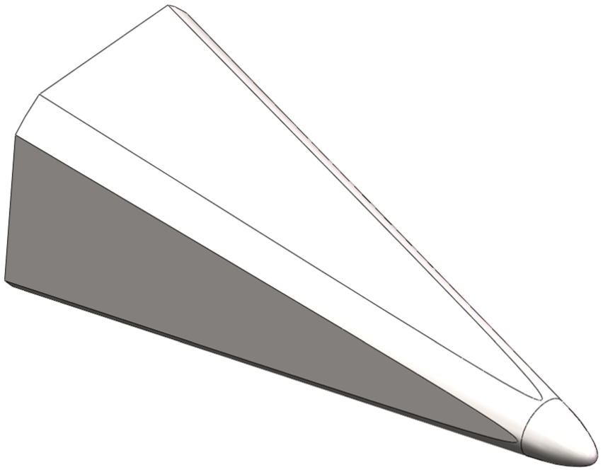
Conceptual schematic diagram of the reentry vehicle.
The related coordinate frames are shown in Figure 2, including the inertial frame, the body frame, and the gimbal frame. The inertial frame E-xeyeze has its origin at the center of the Earth and does not rotate with it. The body frame C-xyz is fixed to the reentry vehicle with its origin at the mass center of the vehicle. The x-axis coincides with the symmetry axis of the vehicle and points toward the head, the y-axis is in the longitudinal symmetry plane of the vehicle and points upward, and the z-axis completes a right-handed frame. The gimbal frame Gi-xgiygizgi is located at the mass center of the ith SGCMG, with the ygi-axis along the rotor momentum, the zgi-axis along the gimbal rotation axis, and the xgi-axis defined by the right-handed rule.

Coordinate frames and scissored pair of SGCMGs: (a) front view and (b) top view.
A scissored pair of SGCMGs is mounted in the reentry vehicle, as shown in Figure 2. The two identical SGCMGs have parallel gimbal axes, which are perpendicular to the roll axis and symmetrical about the symmetrical plane of the vehicle. These SGCMGs rotate in the opposite directions with identical angular velocities. The scissored configuration ensures that the total output torque of SGCMGs aligns with the roll axis, which simplifies the control design. In practice, the identical gimbal angular velocities of the two SGCMGs are guaranteed by a gear or closed-loop control.17,18 Initially, the gimbal angles of the two SGCMGs are set to zero, and thus, the total angular momentum becomes zero. In the state shown in Figure 2(b), it is defined that
During reentry, external disturbance torques may cause saturation of the angular momentum of the scissored pair of SGCMGs, which is referred to as the saturation singularity and disables the attitude control along the roll axis. Therefore, the RCS is used as a complementary attitude control actuator to unload the saturated angular momentum primarily, considering its substantial output torque. Figure 3 illustrates the RCS configuration. There are two sets of thrusters, each of which can provide thrust in both positive and negative directions.

RCS configuration.
Rotational equations of motion
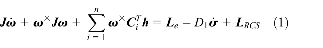
The rotational equations of motion incorporating the SGCMGs and RCS can be derived using the Newton–Euler method. The following dynamic equation is readily obtained from Oh and Vadali 40
where
According to the configuration of the SGCMG pair, the total angular momentum of the rotors

where
Problem description
The control system and control method are designed to realize the stability of the roll angle based on STT control, which is expressed as follows

To this end, attitude control and control allocation laws are developed in this study for the system of compound actuators, which comprises a pair of SGCMGs and an RCS. Furthermore, for single-attitude actuators, the dynamic response ability of the SGCMG is analyzed, and the pulse-width pulse-frequency (PWPF) modulator of RCS is developed.
Attitude control scheme for reentry vehicles
Architecture of compound actuator system
Figure 4 shows the architecture of the proposed compound actuator system. First, the control torque is generated through the roll-channel attitude controller, according to the roll-channel reference attitude input and the measured roll angle and roll rate. Then, the torque command is divided into two parts using the torque allocator. For SGCMGs, the steering logic converts the torque command to the gimbal rate command, which is implemented by the actual gimbal servo mechanism. For RCS, the torque command is modulated by the PWPF modulator. The sum of the actual output torque of SGCMGs and RCS acts on the reentry vehicle, thereby forming the closed loop of attitude control.

Architecture of the compound actuator system.
Four body flaps are used for attitude control for pitch and yaw channels. The control law design is omitted in this study, considering that extensive studies have been conducted regarding attitude control using aerodynamic actuators.
Controller design for roll channel
When the lateral motion parameters are sufficiently small, the approximation

where
The sliding-mode control method is adopted to design the attitude controller for the roll channel. The switching function is selected as

where
In addition, the exponential reaching law is utilized and expressed as

where
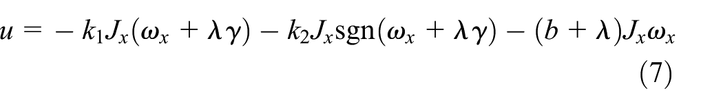
Disregarding the external aerodynamic disturbance torque, the control law is expressed as
To prove the correctness of the control law, a Lyapunov function candidate is selected as

The time derivative of V yields

To ensure that equation (9) is always valid,

When

Then, we can deduce that the values of
To eliminate the chattering problem caused by the discontinuous function

where
Fuzzy control torque allocator design
Given that two actuators implement the torque command generated by the control law in this study, designing a control torque allocation law is necessary for the optimal allocation of the torque command to the SGCMGs and RCS.
Under normal conditions, SGCMGs provide the control torque dominantly, considering their high control accuracy. However, when SGCMGs are near a saturation singularity, RCS is used to unload the redundant angular momentum of SGCMGs. Besides, when the control torque command is larger than the maximum capability of the SGCMG pair, RCS is also used to provide complementary output torque. Therefore, both the singularity measure and control torque command are considered when deriving the control torque allocation law.
To determine the ratios of torque command for SGCMGs and RCS accurately according to the values of the singularity measure and the control torque command, respectively, is difficult. Therefore, the fuzzy reasoning method is considered for designing the torque command allocator. The aim of the allocator is to achieve favorable dynamic response ability while saving the RCS propellant and preventing SGCMGs from approaching a saturation singularity.
Inputs and output of fuzzy allocator
Two input variables for the fuzzy torque allocation block are present, namely, the control torque command ratio and singularity measure of SGCMGs. The control torque command ratio is the result of the control torque command divided by the maximum output torque of the compound actuator, which can be expressed as

where
According to the steering logic of the scissored pair of SGCMGs in equation (25) derived in section “Steering logic of SGCMGs,”

The range of D is from 0 to 1. The large value of D indicates that the SGCMGs are away from the singular state. When D approaches 0, the SGCMGs move toward a saturation singularity.
The output variable of the fuzzy torque allocation block is selected as the ratio of the torque command of RCS to its maximum output torque, which is denoted as w. The torque commands distributed to RCS and the SGCMG pair are, respectively, expressed as


Fuzzy allocator design
The fuzzy system entails a procedure with three phases, namely, fuzzification, inference, and defuzzification.25,41 Detailed design of the three phases is given as follows.
Fuzzification
The input and output variables of the fuzzy inference module are referred to as linguistic variables. For the fuzzy allocation system, the linguistic variables are r, D, and w. To simplify the design of the membership functions and given that all the three linguistic variables are positive, the universe of discourse of the linguistic variables is uniformly selected to be [0, 1]. When
For streamlining the design, only five fuzzy sets are defined: zero (ZE), relatively small (RS), medium (MD), relatively large (RL), and large (LG). To render the fuzzy allocator easy to implement, triangle membership functions, which are widely used in designing fuzzy systems, are suggested. Figure 5 displays the membership functions of the three linguistic variables. For D, the curves of ZE and RS contain the most part of 0–0.5. Thus, when D is approximately below 0.4, the singularity of the SGCMGs can be considered evident, which will enlarge the ratio of the RCS output torque.

Membership functions.
Fuzzy rule base
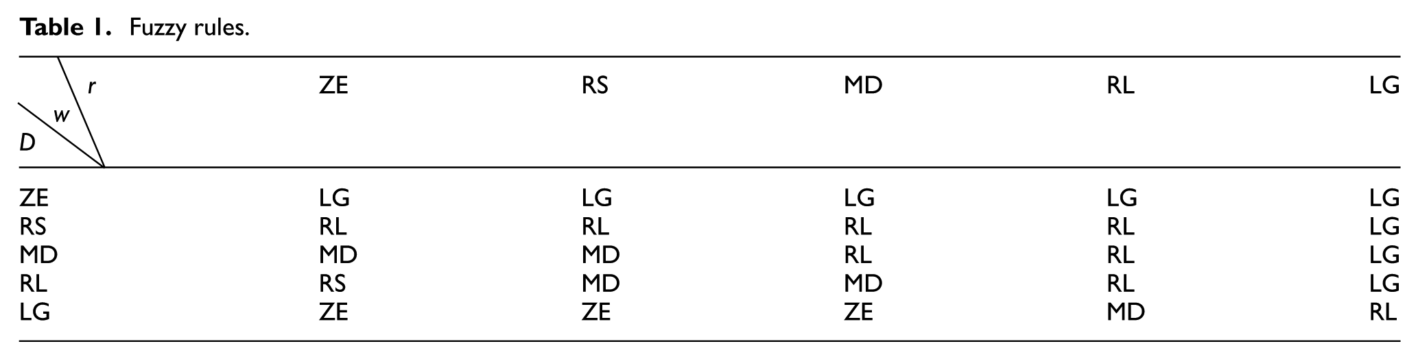
When D is relatively large, the SGCMGs are far from a singularity; thus, the predominant use of SGCMGs as the actuators is expected. When r is relatively large, RCS can be used prior to SGCMGs to provide rapid output torque. Under normal circumstances, SGCMGs are the dominant actuators for minimizing RCS consumption. Based on the above conception, the fuzzy rules are listed in Table 1. Two example rules are given as follows:
If r is RL and D is ZE, then w is LG;
If r is ZE and D is LG, then w is ZE.
Fuzzy rules.
Inference and defuzzification
The Mamdani inference method is used for its characteristics of easy calculation and high efficiency, making it suitable for real-time applications. The center-of-gravity method is used for defuzzification.
Evaluation of SGCMG response speed
Unlike spacecraft orbiting in space, reentry vehicles particularly require that their attitude actuators respond to desired commands in an extremely timely manner. As newly proposed attitude control actuators for reentry vehicles, the responsiveness of SGCMGs requires evaluation to judge their feasibility as actuators during the reentry process.
The response speed of an SGCMG is actually the speed of the gimbal mechanism that reacts to the gimbal rate command. The control diagram of the gimbal mechanism is shown in Figure 6, considering the characteristics of actual servo mechanism dynamics and motor electromagnetics. 42
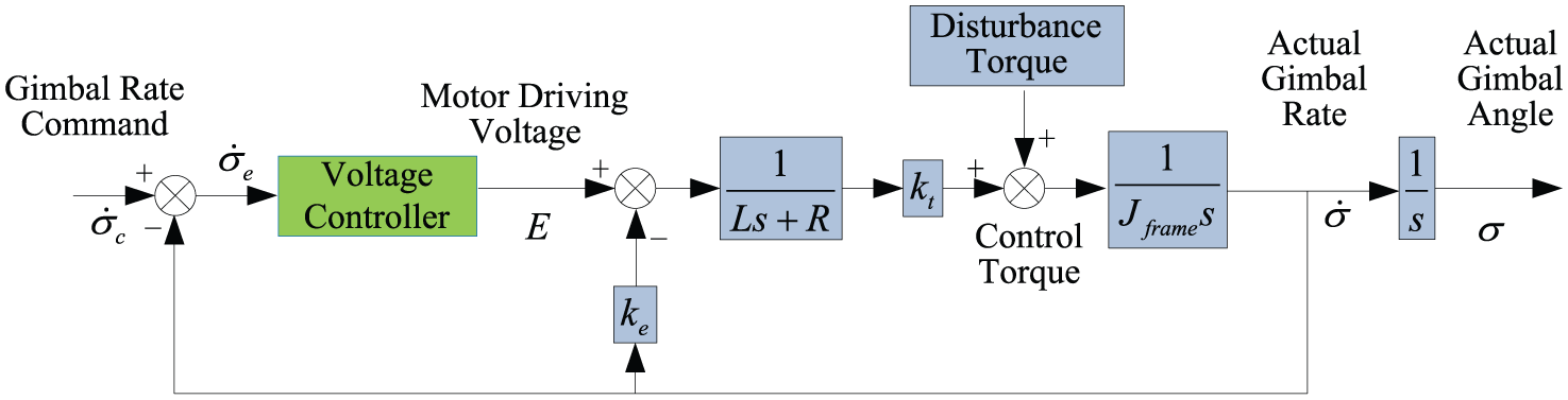
Control diagram of the gimbal mechanism.
Replacing the voltage controller block with 1, the open-loop transfer function of the system can be approximated as a first-order lag, which is expressed as

where
The open-loop gain is calculated as
Disregarding the disturbance torque of the servo mechanism, the closed-loop transfer function can be expressed as

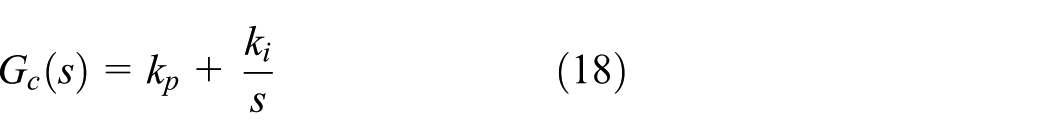
The introduction of the integral term to the controller guarantees zero steady-state error. Good dynamic and static performances may be achieved through reasonable tuning of the parameters of the PI controller.
Now that the transfer function between the commanded gimbal rate and the actual one has been obtained, if the related parameters are given, then the step response curve can be plotted, and the response speed of the SGCMG can be analyzed.
An example is simulated, selecting the related parameters such as

A 15-N m s SGCMG prototype.
According to the measured parameters, the electromechanic time constant can be calculated as

Step response of the gimbal mechanism control system.
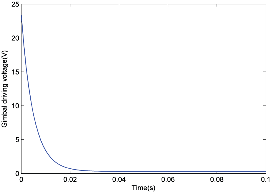
Time history of the gimbal driving voltage.
From Figure 8, it is found that the gimbal rate can rise to 19.1°/s in only about 33 ms. There is almost no overshoot, and the steady-state error is zero. From Figure 9, it is evident that the maximum value of the gimbal driving voltage is approximately 23 V, which is not greater than the required 28 V. If a more powerful servo motor is used, then the responsiveness of the gimbal mechanism can be further improved. Therefore, we can draw the conclusion: compared with the response speed of RCS, which is of an order of magnitude of 10 ms, 13 SGCMGs can also be used as the attitude control actuators of reentry vehicles.
Steering logic of SGCMGs
The two SGCMGs in the scissored pair have the same magnitude of angular momentum, namely,

According to the moment of momentum theorem

Thus, we can obtain the following expression
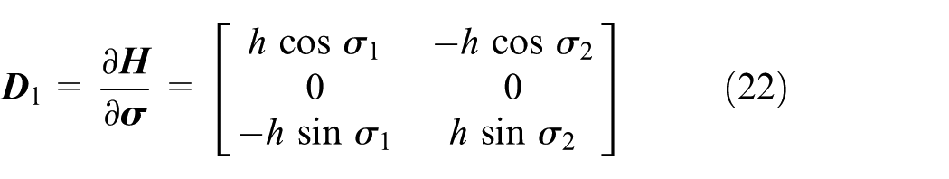
Therefore, the total output torque of the SGCMGs can be calculated as

The conception of the scissored pair of SGCMGs is to generate output torque exclusively along the roll axis. Hence, the y and z components of

The scissored pair of SGCMGs can avoid internal singularity based on the following reasons: with the scissored-pair configuration, the output torque of the SGCMG pair does not change its direction and is only along the x-axis. Besides, the desired control torque is exactly along the x-axis. These facts make the SGCMG pair not encounter internal singularity which is the problem of traditional SGCMGs with the output torque direction always changing.
18
Also, we can see from equation (24) that when
The steering logic is designed to compute the gimbal rate necessary to produce the desired output torque. Some frequently used steering logics include exact methods such as the pseudoinverse steering logic and the gradient method and methods allowing torque error such as the singularity-robust steering logics.43–45 Most of these steering logics are designed to avoid internal singularity. For the scissored pair of SGCMGs, the internal singularity is avoided inherently. Thus, from equation (24), we can directly obtain an internally singularity-free steering logic shown as

The steering logic (25) is easy to implement. However, to make the steering logic work well, the relationship
PWPF modulator of RCS
Given that the RCS uses on-off thrusters to provide control torque, continuous torque command should be modulated to discretize on-off command for implementation.
In comparison with conventional modulators, the PWPF modulator has several advantages, such as closer-to-linear actuation, higher accuracy, and less thruster firing.46,47 Therefore, the PWPF modulator is adopted in this study, and its architecture is shown in Figure 10.

PWPF modulator architecture.
The modulator consists of a first-order filter, a relay with dead zone and hysteresis or Schmidt trigger, and a feedback loop.
48
The output of the PWPF modulator is a train of pulses with values of 1, 0, or −1, which indicates that the thruster injects in the normal direction, stops, or injects in the opposite direction, respectively. The actual output torque of RCS is delayed by the time constant
Numerical simulation
According to the preceding theoretical design, numerical simulation is conducted in this section for validity demonstration. Using the data of EXPERT
16
for reference, the moment of inertia of the reentry vehicle about the roll axis is selected as
Parameters of attitude controller and PWPF modulator.

Two cases are simulated in this section. In both cases, the gimbal servo system model of the SGCMG is included, and the related parameters are given in section “Evaluation of SGCMG response speed.” In case 1, the attitude angle error is not large, the RCS is not working, and there is no external disturbance torque. The aim of simulation of case 1 is to verify the performance of the scissored pair of SGCMGs, which is compared with the results of HILS experiment. The initial conditions are
Results and discussions of case 1
Time histories of related parameters are shown in Figures 11–18. In Figures 11 and 12, it can be seen that the roll angle rises from −10° to 0°, and the roll rate reaches zero within approximately 3.5 s. There is no overshoot during the step response process of the roll angle. Figure 13 depicts a comparison of commanded and actual control torques. It is observed that the actual torque coincides with the commanded torque well except when the gimbal rate reaches its maximum of ±19.1°/s, and the actual torque is saturated. Figures 14 and 15 show the time histories of commanded and actual gimbal rates of SGCMG1 and SGCMG2. It can be found that the actual gimbal rate can follow the commanded gimbal rate well except when the gimbal rate is saturated. Figure 16 is the time histories of gimbal angles of SGCMG1 and SGCMG2. From this figure, it is noted that SGCMG1 and SGCMG2 rotate in the opposite directions. Time histories of singularity measure and angular momentum of SGCMG pair are shown in Figures 17 and 18. It can be seen that the angular momentum does not exceed its maximum of 30 N m s. Results in Figures 16–18 show that the SGCMG pair is far from a singularity during the control process. The effectiveness of the proposed sliding-mode controller and the good performance of the scissored pair of SGCMGs are demonstrated by the above results and discussions.

Time history of roll angle of Case 1.

Time history of roll rate of Case 1.

Time histories of commanded and actual control torques of Case 1.

Time histories of commanded and actual gimbal rates of SGCMG1 of Case 1.

Time histories of commanded and actual gimbal rates of SGCMG2 of Case 1.

Time histories of gimbal angles of SGCMG1 and SGCMG2 of Case 1.
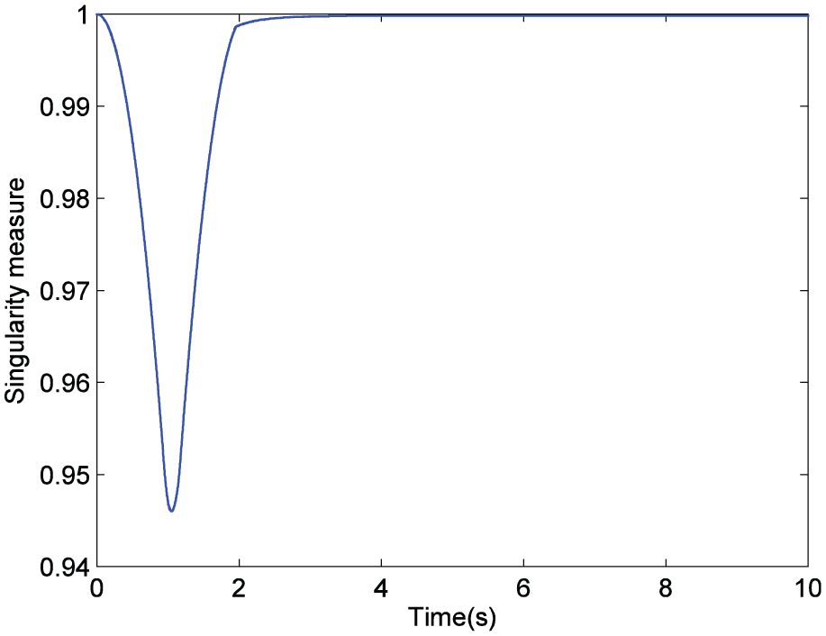
Time history of singularity measure of Case 1.

Time history of angular momentum of SGCMG pair of Case 1.
Results and discussions of case 2
In case 2, RCS and SGCMGs work as compound actuators. The results are shown in Figures 19–30. Figures 19 and 20 indicate that the roll angle and roll rates can be stabilized at zero within approximately 4 s, although the initial roll angle and roll rate errors are large. From 0 to 2.8 s, because of the large commanded torque, both the RCS and SGCMG pair work with their maximum capability to rapidly eliminate the roll angle and roll rate errors, as shown in Figures 21–25. From 2.8 to 10.0 s, it can be seen from Figure 21 that the value of commanded torque is within the output capability of the SGCMG pair, and the pair is far from the singular state; hence, according to the proposed fuzzy torque allocator, the SGCMG pair is utilized as the only attitude actuator to provide accurate control. Figure 21 shows that the curve of the output torque of the SGCMG pair is almost the same as that of the commanded torque during the 2.8 to 10.0 s interval. Besides, from Figures 19, 20, and 27, it is noted that the external disturbance torque is successfully eliminated, and the roll angle and roll rate remain at zero without any chattering. Hence, the effectiveness of rejecting external disturbance of the proposed sliding-mode controller is verified. It is also noted from Figures 29 and 30 that the singularity measure of the SGCMG pair exhibits a falling trend, and the angular momentum exhibits a rising trend during the 5 to 10.0 s interval. This is because the constant portion of the external disturbance torque is absorbed by the SGCMG pair. The results of case 2 demonstrate the feasibility of the proposed fuzzy torque allocator.

Time history of roll angle of Case 2.

Time history of roll rate of Case 2.

Time histories of commanded and actual control torques of Case 2.

Time history of output torque of SGCMG pair of Case 2.
Time histories of commanded and actual gimbal rates of SGCMG1 of Case 2.

Time histories of commanded and actual gimbal rates of SGCMG2 of Case 2.

Time history of output torque of RCS of Case 2.

Time history of commanded torque of RCS of Case 2.

Time history of external disturbance torque of Case 2.

Time histories of gimbal angles of SGCMG1 and SGCMG2 of Case 2.
Time history of singularity measure of Case 2.

Time history of angular momentum of SGCMG pair of Case 2.
HILS experiment
In this section, the HILS experiment is conducted to verify the proposed sliding-mode controller with the scissored pair of SGCMGs as the actuators. The results are analyzed and compared with those of case 1 in the numerical simulation section. As the RCS is not available currently, the fuzzy torque allocator is not implemented in the HILS experiment.
HILS system overview
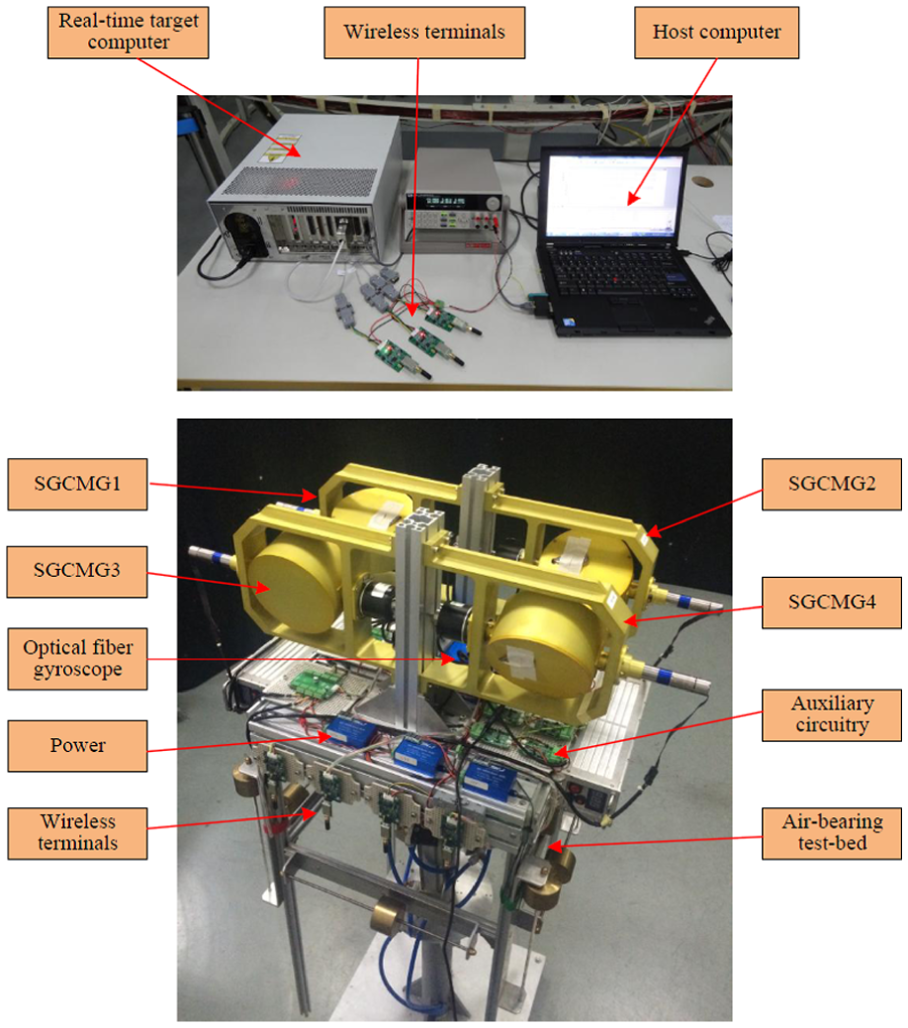
The hardware of the HILS system mainly consists of a real-time target computer, a host computer, an air-bearing test bed, four SGCMGs, an optical fiber gyroscope, and several wireless terminals, as shown in Figure 31. The real-time target computer is used to run the sliding-mode controller in real time. The host computer is utilized to implement the controller in C code and download the code to the real-time computer. Besides, the host computer serves as the monitor of parameters when the real-time code is run. The wireless terminals are developed for remote communications instead of cable connections to avoid disturbances. The air-bearing test bed provides a nearly torque-free environment for the attitude control experiment. Four SGCMGs are mounted on the test bed, among which SGCMG1 and SGCMG3 are used as the scissored pair of SGCMGs, and SGCMG2 and SGCMG4 are used as the backups and balance weight currently. The optical fiber gyroscope is utilized to measure the roll rate.
Air-bearing test bed–based HILS.
The moment of inertia of the test bed including all equipment mounted on it is measured as
Results and discussions
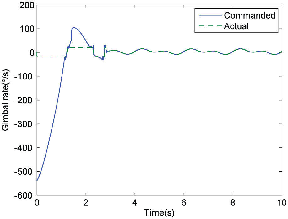
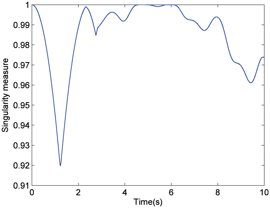
The real-time simulation step and period are set to 20 ms and 10 s, respectively. The results are shown in Figures 32–37. From Figure 32, it can be seen that the roll angle is stabilized around zero in about 3 s. If there exists the roll damping moment, the time will be closer to that of case 1 in the numerical simulation section. From Figures 32 and 33, it is observed that the trends of the roll angle and the roll rate during the 0 to 2 s interval coincide well with those of case 1 in the numerical section. There is no overshoot during the step response process of the roll angle as well. From Figures 34 and 35, we can see that the gimbal rate reaches its maximum of ±19.1°/s, and the actual torque is saturated during the most time of the 0 to 2 s interval. From Figures 36 and 37, it is noted that the SGCMG pair is far from a singularity during the control process. During the 2 to 10 s interval, we can see that the roll angle and roll rate are fluctuating. The reasons can be stated as follows: as the SGCMGs used in the HILS system are developed as rapid prototypes, some drawbacks are neglected during the manufacturing and assembly process, such as the gear gap of the gimbal gear motor and the unbalancing of the high-speed rotor (4700 r/min). These two drawbacks are considered as the main causes of fluctuating. Apart from the undesired fluctuating results, the performance of the proposed sliding-mode controller using a scissored pair of SGCMGs is demonstrated to some extent. Further research will overcome these drawbacks, and better results are expected.

Time history of roll angle of HILS experiment.

Time history of roll rate of HILS experiment.

Time histories of commanded and actual control torques of HILS experiment.

Time history of gimbal rate command of SGCMG1 of HILS experiment.

Time history of gimbal angle of SGCMG1 of HILS experiment.

Time history of singularity measure of HILS experiment.
Conclusion
For some axisymmetric reentry vehicles such as the EXPERT and the DART, the aerodynamic torque along the roll axis is much smaller than those along the pitch and yaw channels. This makes it possible to use the SGCMGs, which are commonly used in spacecraft, as the roll-channel attitude actuators. SGCMGs have the advantages of high accuracy and ability of producing control torque during the whole reentry process. However, they may encounter the problem of saturation singularity, which entails the use of RCS as the complementary actuator. To produce control torque exclusively along the roll axis and avoid internal singularity, two SGCMGs are configured as a scissored pair. The evaluation results of the response speed of the SGCMG show that the gimbal rate can rise from zero to its maximum in only about 33 ms, indicating that SGCMGs are fast enough to be used as the attitude control actuators of reentry vehicles. Numerical simulation results demonstrate the feasibility of the proposed fuzzy torque allocator and the good performance of the proposed sliding-mode attitude controller in the presence of external disturbances. Unlike most literature, the HILS experiment is conducted in this article, the results of which verify the performance of the proposed sliding-mode controller using a scissored pair of SGCMGs.
Footnotes
Handling Editor: Anand Thite
Declaration of conflicting interests
The author(s) declared no potential conflicts of interest with respect to the research, authorship, and/or publication of this article.
Funding
The author(s) disclosed receipt of the following financial support for the research, authorship, and/or publication of this article: This work was financially supported by the National Natural Science Foundation of China (nos 61603405, 61503395, and 61304036) and the Natural Science Foundation of Hunan Province, China (2015JJ3019).