
Abstract
An ideal inerter has been widely used in various vibration isolation fields. Due to its mechanical construction, some nonlinear properties of the inerter need to be taken into consideration. This article concerns the nonlinearities of the fluid inerter and its impact on vehicle suspension performance. A complete nonlinear dynamic model of the fluid inerter is introduced, and the sensitive analysis of the designed parameters is studied. Comparing to the traditional passive suspension, the vehicle suspension performances of three different suspension layouts incorporating the nonlinear fluid inerter are investigated at different velocities and different spring stiffness. Furthermore, the influences of the nonlinearities in frequency domain are also noted. Results show that the nonlinear properties of the fluid inerter have a great effect on vehicle suspension performance except S2 suspension. The impact is more significant in low frequency domain of the vibration.
Vehicle suspension is the general term of power transmission device between wheels and vehicle body. The performance of suspension has a great impact on the vehicle ride comfort, handle, and stability. 1 Active suspension 2 and semi-active suspension 3 have been widely known and used in high-class passenger cars because a passive suspension system cannot preserve the two desired aims which are vehicle handling and passenger comfort very well. Recently, a new kind of passive vehicle suspension system employing the inerter, a new mechanical element, has been heatedly discussed.
Inerter was first proposed by Professor Smith 4 in Cambridge University for the appreciation of the gap in the old analogy between mechanical and electrical networks. It was called “The missing mechanical circuit element,” 5 in that the mass in mechanical circuit element cannot completely correspond to the capacitor in electric circuit element in “force-current” analogy for its one-terminal property. Some research has shown that the performance of traditional spring-damper network can be significantly improved by involving the inerter.
Until now, the inerter has been widely applied to various fields, such as passive network synthesis,6–8 mechanical vibration isolation system including vehicle suspension,9–13 train suspension, 14 building suspension, 15 and the steering compensation for high-performance motorcycles. 16 Furthermore, the influence of inerter on the natural frequencies of vibration systems was investigated in Chen et al. 17 to demonstrate that the inerter can reduce the natural frequencies of the vibration system. In Hu and Chen, 18 the inerter-based dynamic vibration absorbers (IDVA) were proposed by replacing the damper in the traditional dynamic vibration absorber with some inerter-based mechanical networks and significant improvement for both the H∞ and H2 performances was obtained in the numerical simulation. The semi-active inerter was proposed and physically verified in Hu et al. 19 to promote the development of inerter.
Inerter can be mechanically realized in various ways. Mechanical types of the inerter involve the rack-and-pinion inerter and the ball-screw inerter. In Papageorgiou and Smith, 20 the ball-screw inerter and the rack-and-pinion inerter were designed, and experiments were carried out to test their performance. Furthermore, the nonlinearities including friction and the elastic effect were taken into consideration in Wang and Su, 21 the impact on vehicle suspension control was further investigated in time domain. A fluid inerter was presented in Glover and colleagues22,23 and was pointed out that it had the advantage of simpler design than the former ones. Total damping force was analyzed due to the effect of helical channel, port losses, and the viscous shear friction. A nonlinear fluid inerter model with parasitic damping was built and variable orifices and valves were also included to provide series or parallel damping. It means that a fluid inerter can be functioned as an inerter, which is in parallel or in series with a damper. Therefore, a fluid inerter is more suitable for the application in vehicle suspension system because of the limited working space. It is of great interest to analyze the nonlinear properties and their impact on vehicle suspension performance.
In this article, the nonlinear model involving the friction and nonlinear damping force of the fluid inerter is introduced. On the basis of the experimental verification, the nonlinear model is applied to three different vehicle suspensions, and its influences on the vehicle suspension performance in both time domain and frequency domain are discussed. The article is hereafter structured as follows.
In section “Nonlinear fluid inerter,” a more complete nonlinear fluid inerter which involves the friction and nonlinear damping force is introduced and the sensitive analysis of the designed parameters is studied. Three different vehicle suspension layouts employing the nonlinear fluid inerter are built in section “Suspension model incorporating nonlinear inerter.” In section “Analysis of the nonlinearities of inerter,” the impact of the nonlinear properties on suspension performance at different velocities and different stiffness are investigated numerically. The frequency analysis is also carried out in this section, which differs from the other research. Finally, we draw some conclusion in the final section.
Nonlinear fluid inerter
The fluid inerter is similar with the rack-and-pinion inerter and the ball-screw inerter because the fluid flowing in the helical channel can be taken as a “fluid flywheel” to provide the inertia force. As detailed in Swift et al., 23 the damping force is the main nonlinear property of the fluid inerter. The inertance and the damping coefficient will be synchronously changed when there is a variation of the designed parameters. It was noted that the viscous damping force which considered the secondary flow in helical channel was very close to the result of using Hagen–Poisseau formula for a straight tube of circular cross. Since the friction between the piston and cylinder cannot be ignored in low frequency, 21 a more complete nonlinear model of the fluid inerter was proposed in Shen et al. 24 and illustrated in Figure 1.

Nonlinear model of fluid inerter.
The force between the two terminals of the fluid inerter is given by

where z1, z2 are the displacements of the two nodes of the fluid inerter, f is the friction between the piston and the hydraulic cylinder, fc is the nonlinear damping force, fb is the inertia force, f0 is the amplitude of the friction, and sign(v) is a symbolic function. 21 The direction of friction f is determined by the velocity of the piston. b is the inertance, and C1 and C2 are the damping coefficients and can be calculated by the following equations 24
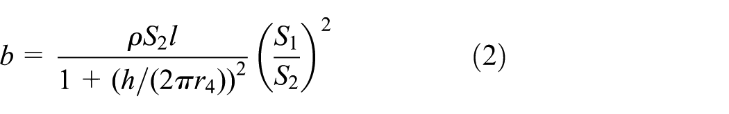
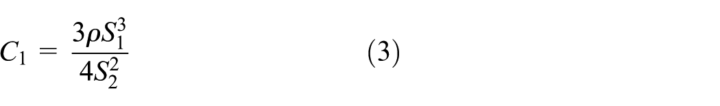

where S1 is the effective area of the hydraulic cylinder, S2 is the section area of the helical channel, ρ is the oil density, l is the length of helical channel, r3 and r4 are the radius of the helical channel and the helix radius of channel, h is the pitch of helical channel, and μ is the viscosity of fluid. In this article, S1 is 0.002 m2, S2 is 0.0000785 m2, ρ is 800 kg m−3, l is 8.99 m, r3 is 0.005 m, r4 is 0.1 m, h is 0.012 m, and μ is 0.027 Pa s. The fluid inerter was manufactured and the bench tests were carried out in Jiangsu University. The nonlinear model of the fluid inerter was verified and details are introduced in Shen et al. 24 The scheme of the fluid inerter and bench tests are depicted in Figure 2.
Prototype of fluid inerter: (a) scheme of fluid inerter and (b) bench test.
From the nonlinear model of the fluid inerter, it can be seen that the friction is determined by the materials between the cylinder and the piston, and the damping coefficient C1 is related to S1 and S2. When the device is completed, both of the f and C1 cannot changed by ignoring the variation of the oil density and the viscosity of fluid. But for b and C2, they all related to l. So, the relationship of b and C2 can be given by

It can be seen from equation (5) that b and C2 will be synchronously changed by the variation of h and r4. Different inertance and the corresponding C2 can be obtained by tuning h and r4 to build up the nonlinear model of the fluid inerter.
In order to show the different influences of h and r4 on b and C2, sensitive analysis is carried out and the results are shown in Figures 3 and 4. As h is usually larger than the twice of r3, the range from −10% to +50% of r4 and h are considered.

Sensitive analysis of r4.

Sensitive analysis of h.
From the above figures, the variation of r4 has a dramatic effect on the parameters b and C2. But for h, there is little change in both b and C2 when changing h. So, it can be concluded that the helix radius of channel r4 is the most important factor to determine the inertia force and the damping force. Different parameters can be achieved by means of tuning r4 when the device is completed.
Suspension model incorporating nonlinear inerter
The general quarter car model is illustrated in Figure 5, with dynamic equations as follows

where ms is the sprung mass set as 320 kg, mu is the unsprung mass set as 45 kg, Kt is the stiffness of the tire set as 190 kN m−1, and F is the suspension force. zs and zu are the vertical displacements of the sprung mass and the unsprung mass. zr is the road roughness displacement and can be gained by the equation

where zr(t) is the road roughness displacement, Gq is the road roughness coefficient, when the car is driving on a B-grade road, it is 64 × 10−6 m3 cycle−1. v is the velocity, w(t) is the integral white noise.

General quarter car model.
In order to analyze the effect of nonlinearities on vehicle suspension performance, four different suspension layouts are shown in Figure 6.

Four configurations of suspension.
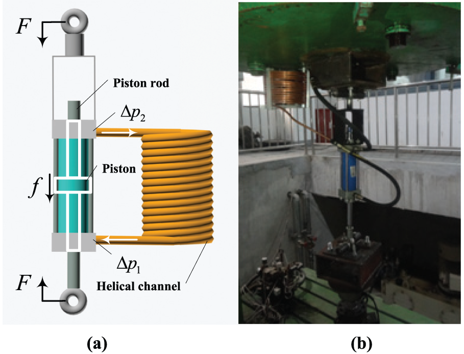
Note that S0 is the traditional passive suspension, the force F0 is shown in equation (8). S1 is a basic parallel arrangement, and the force F1 is shown in equation (9). S2 is a basic series arrangement, and the force F2 is shown in equation (10). The S3 suspension, known as a TID system in Lazar et al., 25 was also investigated in Shen et al. 26 in vehicle suspension. The force in the S3 structure F3 is shown in equation (11), where zb is the vertical displacement of the inerter


Analysis of the nonlinearities of inerter
In order to evaluate the vehicle suspension performance, three performance indexes are considered as follows.
J 1 represents the root mean square (RMS) of the vehicle body acceleration

J 2 represents the RMS of the suspension deflection
J 3 represents the RMS of the dynamic tire load

For the vehicle suspension system, a spring is usually used to support the weight of vehicle body. In order to analyze the different effect of the nonlinearities of the fluid inerter on vehicle suspension performance, the spring stiffness is fixed. A traditional passive suspension from a passenger car is made as a comparison, and the parameters of the linear suspension S1, S2, and S3 are optimized by means of genetic algorithm, which are detailed in Shen et al. 26
In the optimization, the multi-objective is changed to single-objective, the objective function is set as the linear combination of the performance indexes of the vehicle suspension employing inerter and the passive suspension as shown in equation (15)
where BA, SWS, and DTL are the RMS of the body acceleration, suspension deflection, and dynamic tire load of the suspension employing inerter, respectively. BApas, SWSpas, and DTLpas are the RMS of the body acceleration, suspension deflection, and dynamic tire load of the passive suspension, respectively.
According to equations (2)–(4), it is noted that b and C2 will be synchronously changed by the variation of l, which is related to h and r4 from Shen et al. 24 The friction f0 and C1 are fixed, and the different b and C2 are obtained according to the relationship from equation (5). The parameters of the several suspensions are shown in Table 1.
Suspension parameters.

The nonlinearities of a ball-screw inerter, namely dry friction and elastic effect, were separately discussed in Wang and Su, 21 and the different values of the friction and elastic effect are taken into consideration. For the fluid inerter, the effect of the friction and the nonlinear damping force are also investigated separately.
When the vehicle is driving on a B-grade road at a velocity of 20 m s−1, Table 2 shows the performance indexes of the different suspensions. The ideal suspensions are the linear system without considering the nonlinearities. Then, the nonlinearities shown in Table 1 are added in the systems to show the influence of them on the performance indexes. Three scenarios, namely inerter with the friction (fb + f), referred to equation (1), inerter with the damping force (fb + fc) and inerter with both the friction and the damping force (fb + fc + f), are taken into consideration to evaluate its impact on the suspension performance.
Performance indexes.

Comparing with the passive suspension, there is 41.10% decrease in J2 value for ideal S1 suspension, while for the body acceleration and the dynamic tire load, it is usually larger than the passive suspension when the spring stiffness is not very large. It can be seen that the nonlinearities of the fluid inerter sharply increase the J1, and the friction plays a more important role than the nonlinear damping force. But for J2 and J3, they are decreased by the nonlinearities.
For S2 analyses, there is a slight increase in J1 and a negligible variation in J3 when considering the nonlinearities of the fluid inerter. A decrease in J2 can also be seen except the scenario of involving the damping force only.
For S3 layout, all the performance indexes J1, J2, and J3 are increased. Comparing with the passive suspension, the performance improvements are changed from 5.37% to −18.86% of J1, from 23.97% to 4.11% of J2, and from 6.16% to 1.29% of J3. It can be also inferred that the friction has a more effective influence than the nonlinear damping force.
It is noted that the friction cannot be ignored in the nonlinear model, and the three suspensions employing a nonlinear fluid inerter are all greatly influenced by the nonlinearities except S2, on which the impact is quite slight.
Performance evaluation at different velocities
In this section, the suspension performances are analyzed at different velocities. This article assumes that the vehicle is driving on a B-grade road, Figures 7–9 show the performance indexes and the improvement comparing to the passive suspension S0 at velocities from 5 to 50 m s−1, where S1(N), S2(N), and S3(N) represent for the suspensions involving a nonlinear fluid inerter.

(a) J1 at different velocities and (b) improvement of J1 at different velocities.

(a) J2 at different velocities and (b) improvement of J2 at different velocities.

(a) J3 at different velocities and (b) improvement of J3 at different velocities.
From Figures 7–9, J1 of S1(N), S2(N), and S3(N) are all increased by considering the nonlinearities of the fluid inerter. But the variation of S2(N) is smaller than that of S1(N) and S3(N). For J2, all the performance indexes are smaller than S0. S3(N) is larger than S3, while the results for S1(N) and S2(N) are the contrary. Compared with the variation of S1(N) and S3(N), the change of S2(N) is not obvious. For J3, there is a slight decrease in S1(N), and a dramatic increase in S3(N). At the same time, the variation of S2(N) is negligible.
Performance evaluation at different stiffness
There is a wide range of the spring stiffness from a passenger car to a sports car. The suspension performance at different stiffness by considering the nonlinear effect will also be discussed. Note that there is another spring K2 in S3 suspension. The effect of the K2 stiffness on S3 suspension will be investigated first. The performance indexes are shown in Figures 10–12 with the variation of K2.
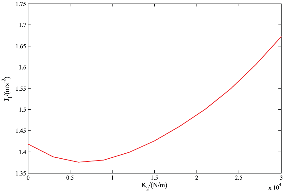
J 1 at different K2 stiffness.

J 2 at different K2 stiffness.

J 3 at different K2 stiffness.
It can be seen that J1 will decrease at first and then dramatically increase. The same trend can be seen for J2 value. But for J3, it will continuously decrease with the increase in the K2 stiffness. Note that when K2 stiffness is closed to the main spring stiffness K = 22,000 N m−1, a relative small value of J2 and J3 can be obtained. However, a large J1 value, which is even larger than the passive suspension, is achieved. The results show that the K2 stiffness plays an important role when selecting the parameters of the S3 suspension. Therefore, the K2 stiffness is determined by the optimization and fixed when analyzing the suspension performance at different main spring stiffness.
Figures 13–15 show the performance indexes and the improvement comparing to S0 at stiffness from 10 to 50 kN m−1.

(a) J1 at different stiffness and (b) improvement of J1 at different stiffness.

(a) J2 at different stiffness and (b) improvement of J2 at different stiffness.

(a) J3 at different stiffness and (b) improvement of J3 at different stiffness.
At different main spring stiffness, the J1 values of nonlinear suspensions are all larger than the linear suspension. But for J2, the nonlinear suspensions S1(N) and S2(N) are smaller than the linear suspensions S1 and S2, and also the same case of S3(N) when the spring stiffness is very small. With the increase in the spring stiffness, the J2 value of S3(N) is larger than that of S3. Meanwhile, all the J2 values are smaller than that of S0 except S3 and S3(N) with a small stiffness. For J3 analyzes, the S1(N) and S2(N) are smaller than S1 and S2 with a small stiffness, while the results are contrary with a large stiffness. But for S3, the J3 value of S3(N) is always larger than that of S3 considering the nonlinearities’ effect. It is noted that, for S2(N), all of the variations in J1, J2, and J3 are relatively small compared with that in S1(N) and S3(N).
To conclude, the influences of the fluid inerter nonlinearities on the suspension performance indexes J1, J2, and J3 are quite complex. The J1 values are all increased by taking the nonlinear effect into consideration. For J2, the nonlinear factors will decrease the suspension deflection of S1 and S2 at different velocities and different spring stiffness. However, the J2 of S3 will become larger except with the small spring stiffness. For J3, it will dramatically increased in S3(N), while there is a slight effect on S1 and S2 at different velocities and different stiffness. Results show that the S2 suspension’s performances are rarely affected by the nonlinearities of fluid inerter compared with S1 and S3.
Frequency analysis
The analysis above are all in time domain, but an interesting question is, whether the nonlinearities of the fluid inerter will have a great impact on the suspension performance in low frequency or in high frequency. In order to solve this problem, the performance indexes which are greatly influenced by the nonlinearities, namely J1 and J2 of S0, S1, S1(N), and S3, S3(N), are selected to analyze the frequency changes. Figures 16 and 17 show the power spectrum density (PSD) of vehicle body acceleration and suspension deflection.
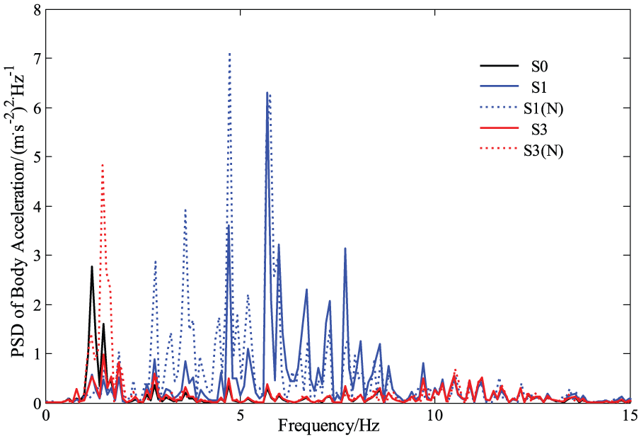
PSD of body acceleration.

PSD of suspension deflection.
From the PSD of body acceleration and suspension deflection, it shows that the nonlinearities of the fluid inerter do have a great impact on the vibration isolation performance of the suspension in the frequency domain. Note that, for the vehicle body acceleration, the PSD of linear S1 and S3 suspensions are all less than the nonlinear model S1(N) and S3(N) suspension, especially in the low frequency domain comparing to the passive suspension S0. For the suspension deflection, the PSD of S1, S1(N), S3, and S3(N) are all less than S0, especially the peak value in the low frequency. While the PSD of linear S3 suspension is less than that of S3(N) suspension, the PSD of linear S1 suspension is much larger than that of S1(N). All of the impacts are more significant in the low frequency regardless of it is becoming larger or smaller.
On the basis of the analysis, it is noted that, for S1 suspension, there is a dramatic decrease in J2 value at different velocities and different stiffness, while J1 and J3 values will become larger at the same time. It is not a good choice to improve the suspension deflection with the cost of degrading the body acceleration and dynamic tire load. For S2 suspension, it is the best one to be applied to the vehicle suspension design because it is rarely influenced by the nonlinearities of the fluid inerter. At last, for S3 suspension, all the performance indexes will be increased by the nonlinearities of fluid inerter except the J2 when the stiffness is quite small. So the nonlinear model of the fluid inerter should be seriously taken into consideration when S3 is applied to the vehicle suspension.
Conclusion
In this article, the nonlinear properties of the fluid inerter, namely the friction and the nonlinear damping force, were taken into consideration to analyze their impact on vehicle suspension performance. The nonlinear model of the fluid inerter was introduced and sensitive analysis of the designed parameters was carried out to study the relationship between inertance and the damping coefficient. Considering the nonlinear effects, three measurements of the vehicle suspensions at different velocities and different spring stiffness were discussed. Results showed that J1 values were all increased by the nonlinear effect. But for J2, it was decreased in S1(N) and S2(N), while increased in S3(N) except small spring stiffness setting. For J3, there was a slight variation in S1(N) and S2(N), but a dramatic increase in S3(N). In general, the nonlinearities’ impact on S2 suspension was not obvious, compared to that on S1 and S3. When a fluid inerter is applied to the vehicle suspension, S2 structure is a better choice to avoid the influence of the nonlinearities. Furthermore, frequency domain analysis was also investigated and it was shown that the effects of nonlinearities of fluid inerter were more significant in low frequency.
Footnotes
Handling Editor: Anand Thite
Declaration of conflicting interests
The author(s) declared no potential conflicts of interest with respect to the research, authorship, and/or publication of this article.
Funding
The author(s) disclosed receipt of the following financial support for the research, authorship, and/or publication of this article: This work was supported by the National Natural Science Foundation of China (Grant No. 51405202). Yujie Shen is also supported by the Scientific Research Innovation Projects of Jiangsu Province (Grant No. KYLX15_1081) and the China Scholarship Council.