
Abstract
Slug rivet should be installed by automatic drilling and riveting machine due to its special structure. The investigation on slug rivet is limited. In order to promote the application of slug rivet, this article conducts investigations on slug rivet installation process. For the understanding of the riveting quality of a riveted lap joint, it is essential to analyze the riveting parameters. There are numerous parameters associated with a riveting process such as squeezing force, rivet structure, countersunk hole structure, hole diameter, sheet thickness, and clamping force. Incorrect selection or variations in these parameters could directly affect the riveting quality. The aim of this article is to study the impact of the aforementioned parameters on the riveting quality of a riveted aircraft structure. The interference condition is considered as the main quality control criterion. The squeezing force is introduced as the most important parameter for the riveting quality. The study provides a deeper understanding of the slug rivet installation process with the impacts of its riveting parameters. This study will pave the way for further researches and extend the scope of the slug rivet application to more structural connections.
Keywords
Introduction
Long fatigue life design of aircraft requires increasingly improvement of the assembly quality. Slug rivet interference-fit riveting technology can significantly improve the fatigue life of aircraft structures with good sealing performance. 1 But slug rivet should be installed using the automatic drilling and riveting machine due to its special structure. 1 The processing equipment is very complex. The study and application of slug rivet are limited. Currently, slug rivet is mainly used in wing panel automatic assembly system with automatic drilling and riveting machine.2–6 To further promote the application of slug rivet interference-fit riveting technology, this study concentrates on studying the slug rivet installation process and the effects of riveting parameters on the riveting quality.
There are numerous parameters associated with a riveting process. Atre 7 investigated the effects of manufacturing process variations on the residual stress state generated in aircraft riveted lap joints. Table 1 lists the parameters and their descriptions. The parameters were based on actual service variations observed in the B727 teardown. Müller 8 studied the effects of parameters on the fatigue performance of a riveted lap joint. The parameters included squeezing force, rivet geometry, rivet type, rivet material, rivet pitch, number of rivet rows, the pitch between the rows, countersink depth, sheet geometry, and sheet material. Müller 8 concluded that the rivet squeezing force was the most important variable among the parameters. Moreover, Mu et al. 9 analyzed the relationship between squeezing force and its relative interference level. Rijck et al. 10 focused on the relationship between squeezing force and the rivet driven head dimension during controlled riveting process. Extensive test series were also conducted with different rivet materials, rivet diameters, and sheet materials. Szolwinski and Farris 11 linked squeezing force to the fatigue performance of riveted aircraft structures. They found that the fatigue life of a riveted lap joint significantly increased with a larger squeezing force.
Parametric variations. 8

The aforementioned parameters determine the riveting quality and the fatigue performance of a riveted assembly. Incorrect selection or variations in these parameters could seriously affect the riveting quality of the riveted structures. However, these researches mainly concentrate on traditional rivets such as protruding rivet and countersunk rivet. Literature review finds that in the field of slug rivet connection, few published literature studies the effects of the parameters on the riveting quality of a riveted structure.
To provide a deeper understanding of slug rivet connection, this article presents an investigation of the impacts of the riveting parameters on the riveting quality of a riveted lap joint using numerical simulations. A baseline finite element model is established and varied. The experiments are conducted using the automatic drilling and riveting machine. The effects of the riveting parameters have been studied. The parameters include squeezing force, rivet structure, countersunk hole structure, hole diameter, sheet thickness, and clamping force. This article improves knowledge about the riveting parameters and their influences on the assembly quality of a riveted lap joint with slug rivet.
Experimental details
The series of NAS1321 slug rivet had been employed in the wing panel assembly system for ARJ-21 regional jet. Figure 1 presented the structural sketch of the specimen. 12 The NAS1321AD6E10 slug rivet was used in this article. The diameter and length of the rivet were 4.76 and 15.88 mm. The protrusion height at each side was equal, PU = PL = 4.94 mm. The riveting edge and rivet pitch were 25 mm.8,12 The sheet material was 7050 Al alloy. The thickness of the sheet was 3 mm. The diameter of the pin hole is 4.91 mm (the permissible hole diameter for the slug rivet used is 4.85–4.93 mm 12 ).
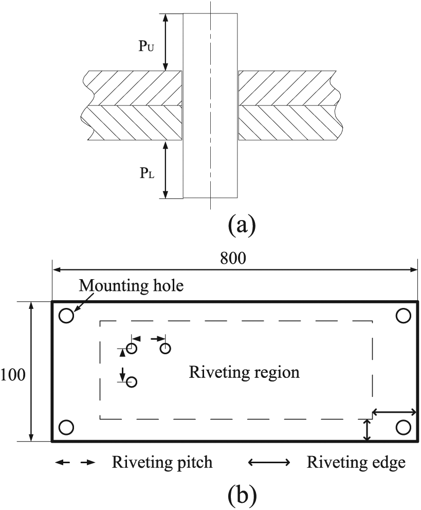
The structural sketch of the riveted lap joint: (a) slug rivet structure and (b) specimen structure.
The experiment was conducted using the automatic drilling and riveting machine developed by Zhejiang University. The equipment had a double-horizontal five-axis structure (Figure 2). The upper and lower riveting position systems were used for moving the riveting head end executors to the proper location. The upper riveting head end executor was used for processes such as clamping the workpiece, drilling, inserting rivet, and riveting. The lower riveting head end executor was used for processes such as clamping and riveting.

The components of the automatic drilling and riveting machine.
The automatic drilling and riveting machine would automatically measure and adjust the perpendicularity between the feed direction and the workpiece before clamping and drilling. Figure 3 illustrates the operation process of the device:
Step 1: the upper and lower head end executors moved to the proper location. The pressure feet clamped the workpiece to avoid movement of the workpiece.
Step 2: the upper riveting head end executor drilled automatically according to the program.
Step 3: the lower riveting head end executor moved to the work starting position. The device fetched the slug rivet and finished the inserting process.
Step 4: the upper riveting head end executor moved to the work starting position. The upper riveting die began to contact with the slug rivet.
Step 5: the upper and lower riveting head end executers began riveting simultaneously.
Step 6: the upper and lower riveting dies drew back after finishing riveting process.

The manufacturing process of the automatic drilling and riveting machine.
For NAS1321AD6E10 slug rivet, the permissible minimum diameter and height of the driven head are 6.198 and 1.346 mm. 12 To meet the dimensional requirement, the squeezing force used in this article is 40,000 N. More than three slug rivets should be installed in the specimen. 12 Figure 4 presents the automatic drilling and riveting process. Five rivets were installed in the middle position of the specimen with the squeezing force of 40,000 N. The automatic drill-rivet equipment provided accurate squeezing force and displacement measurements. The process data were displaced and recorded in the sensor data interface (Figure 4(b)).
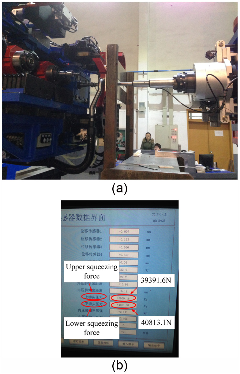
The experimental process: (a) automatic drilling and riveting and (b) sensor data interface.
Simulation study
Modeling
A two-dimensional axisymmetric finite element model is established to simulate the slug rivet installation process.7–9 A force-controlled riveting method is employed. Since force-controlled rivet squeezing gives a much more accurate quality control and a more uniform fatigue performance. 8
The FE model consists of slug rivet, upper and lower riveting dies, upper and lower pressure feet, upper and lower sheets, as shown in Figure 5. The rivet is NAS1321AD6E10 slug rivet. The dimensions of the sheet are (50 × 50 × 3) mm. The dimension is in accordance with the rivet pitch applied in the experiments. The minimum dimension ratio of the sheet and rivet is larger than 6, which is supposed to be enough for a negligible effect of the stress free out boundaries.8,13 The clearance between the hole wall and the rivet shank is 0.15 mm.

The FE model with mesh and boundary conditions.
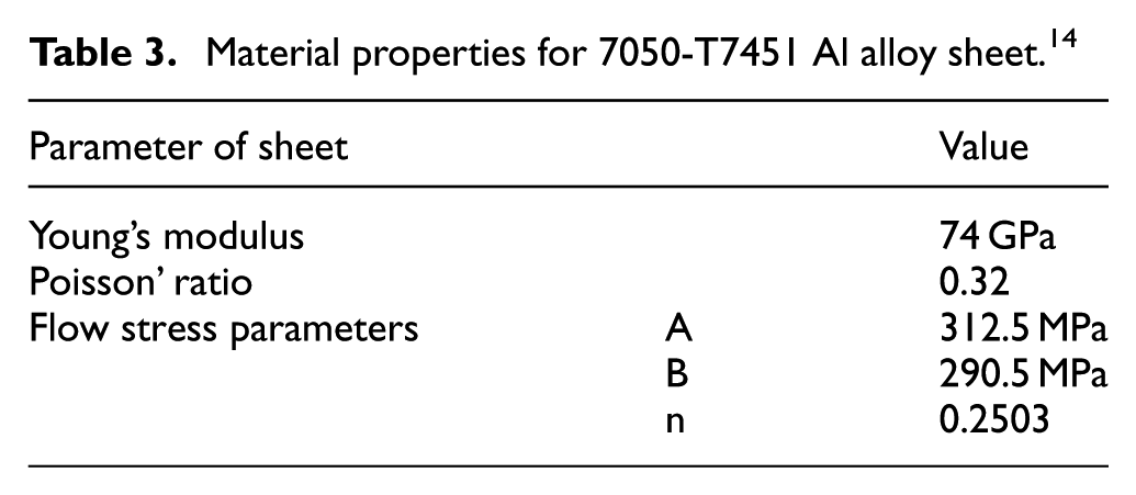
The materials of the rivet and sheet are 2117-T4 and 7050-T7451, whose property parameters are listed in Tables 2 and 3. In Table 2, the coefficient C and m are obtained by substituting the data of tensile tests into equation 1, where ε is the true strain and σ is the true stress. In Table 3, the coefficients A, B, and n are obtained by substituting the data of tensile tests into equation (2).7,14
Material properties for 2117-T4 Al alloy rivet. 16

Material properties for 7050-T7451 Al alloy sheet. 14
The FE model is generated using ABAQUS 6.14 with CAX4R reduced integration four-node axisymmetric elements. Three deformable bodies, two sheets and a rivet, are defined in the model. While the riveting dies and pressure feet are defined as rigid bodies. A typical mesh generation technology is applied. 15 Different mesh sizes are tested to find an optimal mesh density with desired results. Mesh size of the rivet is 0.06 mm. Mesh size of the sheet is 0.08 mm for the area in the vicinity of the rivet hole and 1.2 mm for the region far from the hole


Geometric and surface interaction nonlinearities are included in the model. Surface interactions are defined as contact pairs using the master–slave algorithm. The model includes contacts between the rivet and sheets, the pressure feet and sheets, the riveting dies and rivet, and between the faying surfaces of the upper and lower sheets. The contact interaction is modeled with the Coulomb friction model. A friction coefficient of 0.2 is specified for all interactions.7,11 The NLGEOM option is selected, which means a geometric non-linear analysis.
As illustrated in Figure 5, the sheets surfaces on the far-end are constrained in X-Direction with the Y-Direction nodes constrained at the top and bottom to prevent the sheets motion. 7 All freedom degrees of the upper and lower riveting dies and pressure feet are constrained, except the Y-Direction. The riveting forces are applied at the upper and lower riveting dies. The clamping force of 500 N is applied at pressure feet. The riveting process is simulated in two steps. Step 1 is a loading step. The rivet is gradually deformed by the special riveting forces applied at the upper and lower riveting dies. Step 2 is an unloading step. The rivet can springback since the squeezing forces are released back to 0. The period of each step is 1 ms, which is appropriate to obtain a quasi-static solution and achieve computational efficiency. 7
Model validation
Energetic analysis
Blanchot and Daidie 15 proposed an essential criterion to validate the numerical simulation: for good calculation, the hourglass energy must not exceed 10% of the internal energy at the end of simulation. Figure 6 shows the ratio hourglass energy and internal energy. The data are obtained from the history energy output of the FE model. As can be seen, the ratio is approximately 6% at the beginning of the simulation. Then the value falls dramatically and remains under 0.1% during the whole simulation period. Therefore, a good simulation result is achieved.
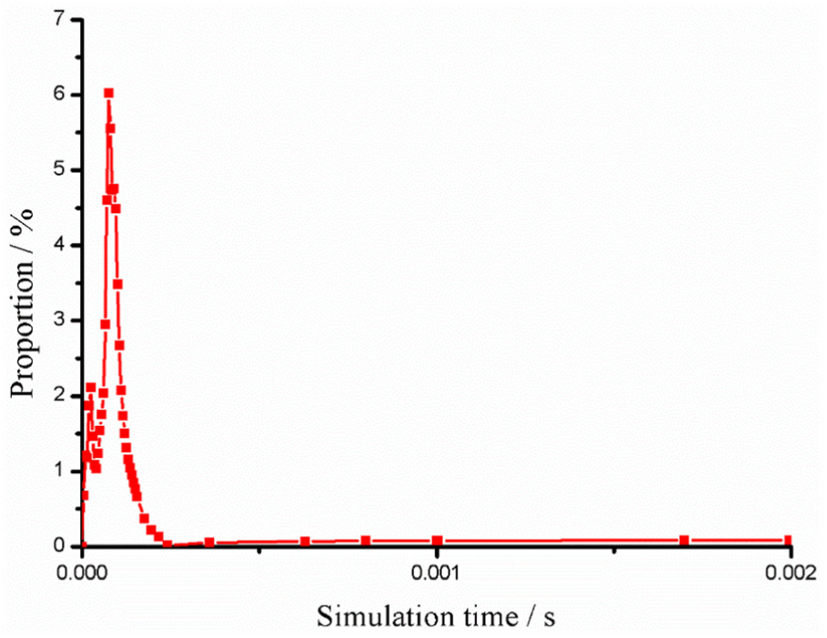
The ratio of hourglass energy and internal energy.
Deformation comparison
The driven head dimension is usually considered as a quality control criterion for riveted joints.10,16 Figure 7 illustrates the deformations obtained from the experiment and numerical results. Five rivets have been installed in the middle position of the specimen. The shape of the driven head obtained from FE model is consistent with the experiment. The cross-section of the specimen (Figure 7(c)) and the simulation results (Figure 7(d)) approximately keep the same. Table 4 presents the comparison of the experimental and numerical driven head dimensions after releasing the squeezing force. Both the results meet the minimum dimension requirement. The dimension difference between simulation and experiment is small. A good agreement is achieved for the rivet driven head deformation. The FE model can provide reasonable rivet deformations.
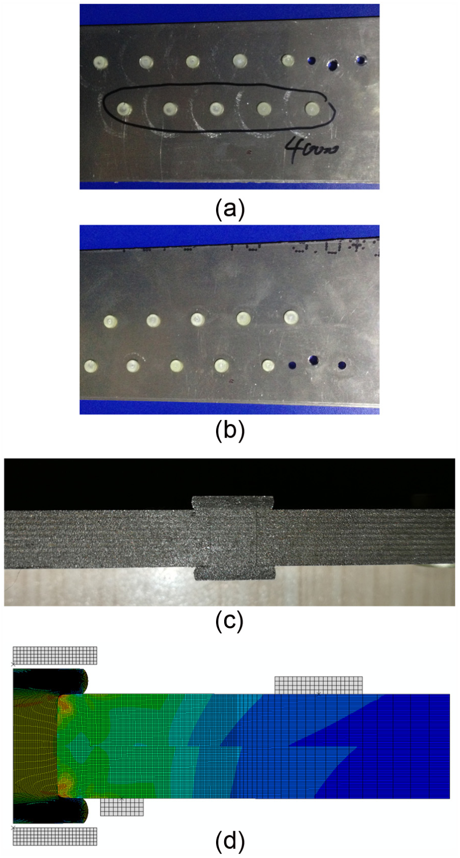
The deformations of experimental specimen and simulation: (a) upper side of the specimen, (b) lower side of the specimen, (c) cross-section of the specimen, and (d) simulation prediction.
Comparison of driven head dimension.

Interference comparison
Interference level is considered as the main quality control criterion for riveted assembly. 8 Figure 8 presents the comparison of the interference value after riveting process. As can be seen, there is a gap between FE and experiment results. The difference is caused by measurement error, material property error, and experimental error. But the variation trends and the value of the two curves are approximately consistent with each other. The minimum value is obtained at the faying surface between the sheets. The interferences become larger at both sides of the driven head. The comparison between the numerical results and experimental measurements is satisfactory in terms of interference condition. The FE model can provide accurate numerical results.

Interference comparison between experiment and simulation.
The energy analysis demonstrates the effectiveness of the simulation. The comparisons of rivet deformation and interference level demonstrate that the FE model can simulate the slug rivet installation processes reasonably and accurately.
Effects of riveting parameters
Squeezing force
Rivet installation implies a squeezing process of the rivet shank with large plastic deformation to form the driven head. Table 5 lists the squeezing force employed in this study. The final dimension of the driven head is shown in Figure 9. Obviously, the dimension of the driven head is significantly impacted by the squeezing force. The curves are nearly a linear function of the applied force. The dimensional measurements of the driven head will allow estimation of the applied squeezing force for quality control of the riveting process with respect to the fatigue performance of the riveted assembly. 10
Data of squeezing force.

The dimensions of all the driven heads are within the permissible dimensional requirement.

Driven head dimension with different squeezing forces.
The effect of squeezing force on the hole expansion during riveting process is great as well. Figure 10 illustrates the interference level combined with different squeezing forces. The larger the applied force is, the higher the interference value is obtained. Since the interference condition is considered as the quality control criterion for riveted assembly, high squeezing force is beneficial for the riveting quality of a riveted lap joint. A tenfold increased fatigue life will even be achieved by larger squeezing force. 8

Interference condition with different squeezing forces.
The magnitude of squeezing force is not only proportional to the final dimension of the driven head, but also responsible for the interference condition. The residual compressive stress induced by rivet interference-fit installation process can significantly improve the fatigue performance of a riveted assembly.8,11 Moreover, squeezing force is controllable during the riveting process. Squeezing force is usually considered as the most important parameter for the quality of a riveted lap joint.8,11
Rivet structure
The dimensions of the rivet diameter and rivet length are given in Table 6. To ensure single variable analysis, the other parameters keep the same with the baseline model.
Data of rivet structure.

Figure 11 presents the driven head dimensions after riveting. For different rivet diameters, the rivet length stays the same. The diameter of the driven heads drops gradually from Group 1 to Group 3 with the increased rivet diameter. While the height of the driven heads increases significantly. For different rivet lengths, the rivet diameter remains the same. The diameter and length of the driven heads raises step by step from Group 3 to Group 5 with the increased rivet length.

Driven head dimension with different rivet structures.
Figure 12 shows the effects of the rivet structure on the interference condition. The variations of the interference value between different rivet diameters are distinct. The interference value becomes smaller with the increased rivet diameter. While the influence of the rivet length on the interference level is not so remarkable. The interference value decreases slightly with the increased rivet length.

Interference condition with different rivet structures.
The interference condition in this section is closely related to the height of driven head. The smaller the height is, the larger the interference value is obtained. When the slope of the height curve gets larger, the variation of the interference value becomes larger as well. While when the slope turns gentle, the variation becomes smaller.
Countersunk hole structure
Figure 13 presents the structure of countersunk hole used in a riveted lap joint with slug rivet.1,12 The structural parameters are given in Table 7.
Data of countersunk hole structure.


The sketch of countersunk hole structure.
During the riveting process, the volume of the rivet cannot fully fill the countersunk hole in Group CH-4. The driven head dimension and interference condition are undesired. The countersunk hole in Group CH-4 is not suitable for NAS1321AD6E10 slug rivet.
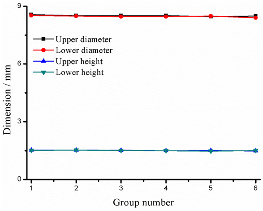
Figure 14 shows the driven head dimensions gained from other three groups. The dimensions (diameter and height) of the lower driven heads are approximately consistent. But the differences between the upper diameters are distinct due to different countersunk hole structures. While the differences between the upper heights are relatively small.

Driven head dimension with different countersunk hole structures.
Figure 15 shows the effects of the countersunk hole structure on the interference conditions. Obviously, without countersunk hole, the interference distribution of the baseline model (CH-1) is homogeneous. The interference distributions with countersunk hole are uneven. The amplitudes and variation trends of the interference distributions in Group CH-2 and CH-3 at the lower sheet keep the same with the baseline model. While the interference conditions at the upper sheet are larger than the baseline model. Moreover, the distribution fluctuates at the junction of hole wall and countersunk hole.
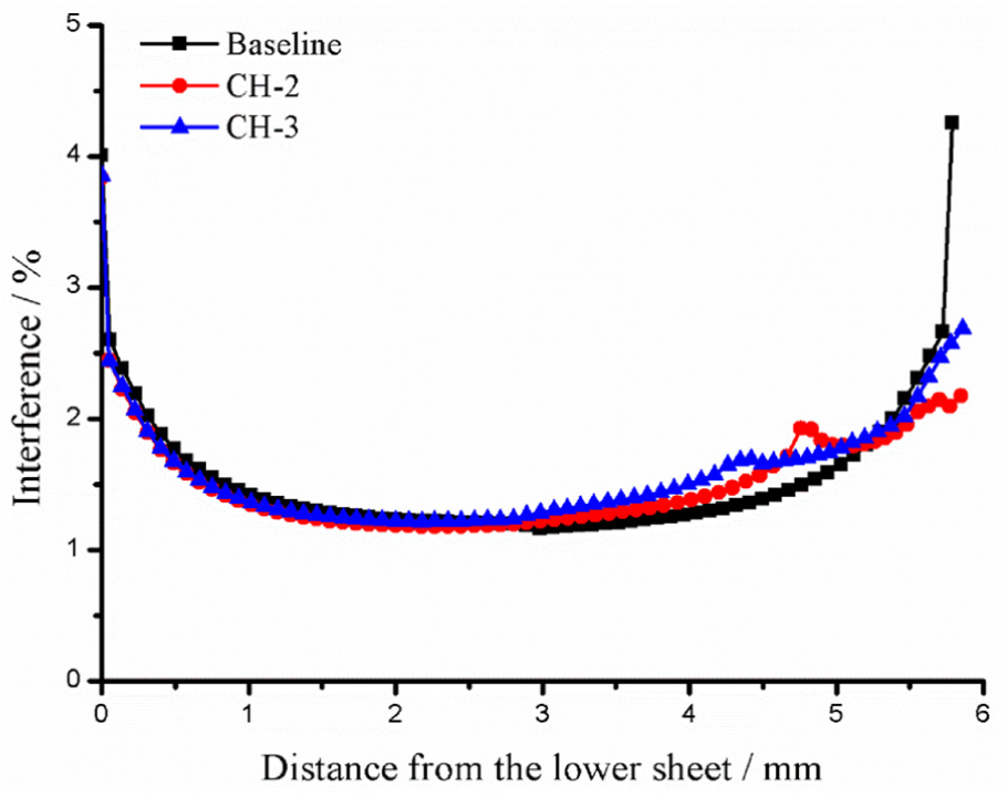
Interference condition with different countersunk hole structures.
Hole diameter
The permissible hole diameter for the slug rivet used in this article is 4.85–4.93 mm. 12 Table 8 lists the hole diameter value adopted in the study.
Data of different hole diameters.

Figure 16 presents the dimensions of the driven head after riveting. Since very few rivet material has been pushed into the hole. The volumes of the driven heads with different diameters are approximately equal. The diameters and heights of the driven heads with different hole diameters almost remain the same. The effects of hole diameter on the interference conditions are illustrated in Figure 17. As can be seen, the variations of interference value between different hole diameters are somewhat apparent. The interference value declines gradually with the increased hole diameter.
Driven head dimension with different hole diameters.

Interference condition with different hole diameters.
In this case, the driven head dimension is not suitable for riveting quality assessment since the dimensions between different hole diameters nearly keep the same with each other. The interference level is better to evaluate the quality since the variation trend between different hole diameters is more obvious. For convenience of rivet inserting, the hole diameter is selected as 4.91 mm in this study.
Sheet thickness
In actual rivet connection, the thicknesses of fuselage panel and stringer may be unequal at some parts of the aircraft. Table 9 presents different thickness combinations.
Data of different sheet thicknesses.

The driven head dimensions with different sheet thicknesses practically stay the same with each other (Figure 18). Since the total thickness of the joint remains the same. The protrusion height at each side of the overlap region is equal (Figure 1).

Driven head dimension with different sheet thicknesses.
However, the effects of the sheet thickness on the interference condition are somewhat prominent, as shown in Figure 19. The interference distribution of baseline model is homogeneous. While the interference distributions of Group PT-1 and PT-3 fluctuate at the junction of sheets. The interference value of the thinner sheet is larger than the thicker sheet. The situation of unequal sheet thickness will result in uneven distribution of interference level.

Interference condition with different sheet thicknesses.
The case in this section further demonstrates that interference condition is more accurate and useful in the assessment of riveting quality. Since the variation trends of the interference distribution is distinct, while the driven head dimensions with different sheet thicknesses are almost consistent.
Clamping force
To avoid the movement of the workpiece during the drilling and riveting process, the pressure feet will clamp the workpiece first. Table 10 lists different clamping forces employed in the study.
Data of different clamping forces.

As can be seen from Figure 20, the driven head dimensions with different clamping forces approximately keep the same with each other. Similarly, the effects of clamping force on the interference value are inconspicuous, as presented in Figure 21.
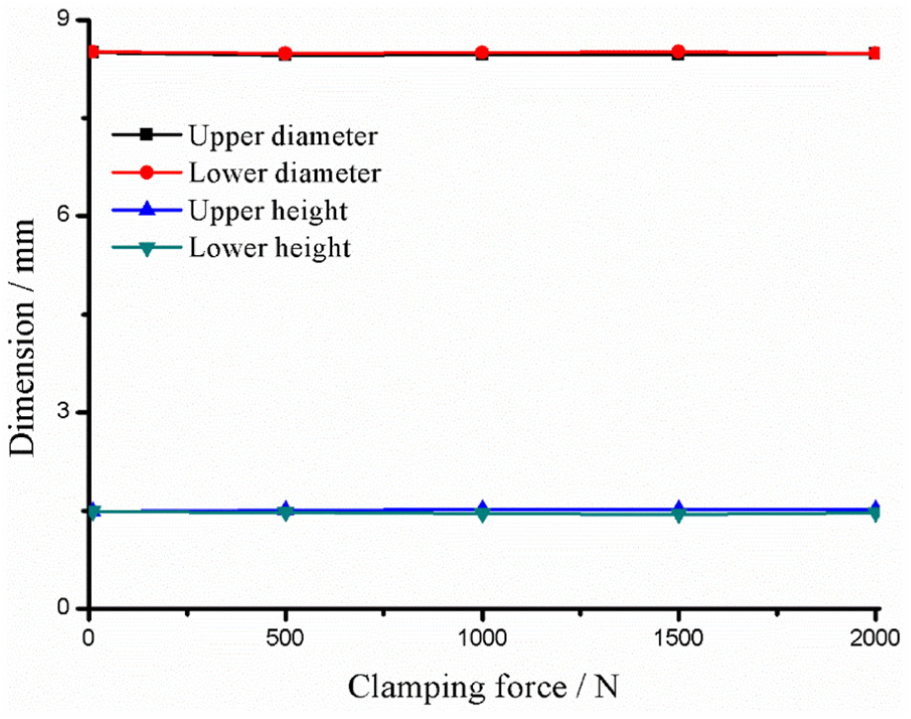
Driven head dimension with different clamping forces.

Interference condition with different clamping forces.
The main impact of the clamping force on the riveted lap joint is sheet deformation. As illustrated in Figure 5, the sheets are clamped by asymmetric structure. The diameter of the lower pressure foot is much smaller than the upper pressure foot. The riveted assembly will deform under the effect of asymmetric clamping force. Figure 22 shows the deformation amplitude of the contact surface of the upper and lower sheets along the thickness direction. The deformation amplitude raises with the increased clamping force. To minimize the distortion and prevent the movement of the sheets, the clamping force is set as 500 N in this study.

Riveted assembly deformation with different clamping forces.
Results synthesis
Schütz 17 points out that the manufacturing process has a prominent effect on the fatigue life of a riveted assembly. Since many riveting parameters during the manufacturing process will impact the riveting quality. The rivet structure, countersunk hole structure, hole diameter, and sheet thickness are geometrical parameters, which should be defined before riveting. The squeezing force and clamping force are the procedure parameters, which are controllable during the riveting process.
The interference level is significantly affected by the riveting parameters studied in this article. While the effects of these parameters on the driven head dimensions are relatively small. The quality of a riveted lap joint will be mainly related to hole expansion. 8 Moreover, among the riveting parameters, the squeezing force, rivet structure, and hole diameter have a more serious impact on the interference condition. Since the rivet structure and hole diameter are determined before riveting operation, the squeezing force is considered as the most important variable for the riveting quality of a riveted structure.
Conclusion
This article presents a study to determine the influence of variations in riveting parameters (i.e. squeezing force, rivet structure, countersunk hole structure, hole diameter, sheet thickness, and clamping force) on the assembly quality of a riveted lap joint. The baseline FE model is validated using three criteria. The developed FE model can provide reasonable slug rivet installation processes with desired results. The simulations establish the relationship between the riveting parameters and the variation trends of the riveting quality. The results indicate that the squeezing force is the most important parameter for the riveting quality. Moreover, the interference condition should be considered as the main quality control criterion. The limitations of the driven head dimensions for assembly quality control are illustrated. This study will be useful in structural connection design using slug rivet. The final gold of this study is to extend the scope of the slug rivet application to more structural connections.
Footnotes
Handling Editor: Yangmin Li
Declaration of conflicting interests
The author(s) declared no potential conflicts of interest with respect to the research, authorship, and/or publication of this article.
Funding
The author(s) disclosed receipt of the following financial support for the research, authorship, and/or publication of this article: This research was supported by the National Natural Science Foundation of China (No. 51775495), Science Fund for Creative Research Groups of National Natural Science Foundation of China (No. 51521064), and Special scientific research for civil aircraft (No. MJ-2015-G-081).