
Abstract
This article proposes a flexure-based leverage mechanism that improves the performance of the static unbalance measurement system in terms of sensitivity and precision. The primary function of the flexure-based leverage mechanism is to transform the objective unbalance force/moment from the double-frame platform to an electromagnetic force balance sensor. A model of the flexure-based leverage mechanism was established to investigate the displacement/force amplification based on the elastic model. The finite element method was used to verify the analytical solutions. Considering the gravity effects, the self-weight of the rigid bodies in this leverage mechanism has an effect on the reading in the sensors. However, the linearity characteristics are not sensitive to the self-weight of the proposed leverage mechanism and the stiffness of the flexure hinges. Virtual experiments conducted to verify the linearity and sensitivity of the system indicated that depending on the leverage function of the flexure-based leverage mechanism, the systematic sensitivity is less than 0.02 g/(g cm), the resolution is 0.0013 g cm, and the maximum linearity error is 2.7%.
Introduction
For unmanned aerial vehicles and mobile robots, gimbaled seekers are crucial components to guarantee precision and reliability during the track procedure.1,2 The centroid of the gimbal off-rotation axle results in unbalance being the primary factor affecting performance. Once a carrier is in the process of vibration or acceleration, the unbalance in the gimbaled mechanism introduces unexpected disturbances into the motion control system, which leads to the carrier escaping from the anticipated trajectory. Only a few gimbaled seekers and rotors assembled can completely overcome this technological barrier and most require correction for actual engineering applications.
For more than 60 years, researchers have focused on investigating unbalance measurement methods for various gimbaled mechanisms.3–8 In general, there are two methods to guarantee operation stability. The first method employs motors with enhanced torque to hold the position of the seeker by increasing the current in a closed-loop servo. However, this method requires much space and is relatively heavy in the carrier. The second method optimises the feedback loop of the control system to improve the systematic anti-disturbance capacity and robustness features.3–6 However, it utilises very expensive electronic components and cannot guarantee performance in extremely rugged situations.
The dynamical unbalance measure method is also a conventional method;9–11 for instance, the vibration is sampled to determine the unbalance by sensing the Coriolis inertial force. The static unbalance measurement method is superior to dynamic measurement methods as it is easy to operate and performs advanced specifications. Tao et al. 12 proposed a static balance method for cupped wave gyros based on cup-bottom trimming. The Space Electronics company13,14 proposed a static unbalance measurement method based on the centroid of gravity projection (CGP). Because the centroid of gravity (CG) moves with the rotation of the unbalanced gimbal/rotor, the corresponding unbalance moment is decomposed in terms of the rotation axis of the double-frame mechanism. Their commercial products have a resolution of 0.1 g cm for a light seeker. Similarly, Yang et al. 15 and Zhan et al. 16 proposed different prototypes for the static unbalance measurement system. Based on Zhan and colleagues early work,16,17 the flexure-based mechanism is proposed and acts as a bridge between the double-frame mechanism and a force sensor. Therefore, the linearity characteristics of the force transmission have significant effects on the measurement precision of this system.
In this study, the flexure-based leverage mechanism was modelled and investigated in order to improve systematic measurement characteristics. We conducted detailed analysis of the flexure-based leverage mechanism based on the elastic model.18–21 In contrast to the work of others on flexure-based mechanisms, a more generalised model was addressed to express the deformation displacement considering the effects of self-gravity. We investigated the force amplification and the linearity characteristics via the analytical model, the finite element method (FEM) and experiments. We also verified the analytical model, which mainly depends on the leverage function of the flexure-based mechanism, via FEM. Our developed static unbalance measurement system has a unique resolution of 0.0013 g cm and maximum hysteresis error of 0.12 g cm, which is superior to our early work and other conventional systems.14,16,17,22,23
The remainder of this article is organised as follows. Section ‘The static unbalance measurement system’ introduces the measuring principle and the structure of the static unbalance system. Section ‘Modelling force transmission’ models the flexure-based leverage mechanism. Section ‘Verification and simulation’ evaluates the force transmission of the flexure-based leverage mechanism and proves the analytical solutions. Section ‘Experimental investigation’ verifies the linearity of the measurement system experimentally. Section ‘Discussion’ discusses the results of simulations and experiments conducted. Section ‘Conclusion’ summarises the flexure-based leverage mechanism of the static unbalance measurement system.
The static unbalance measurement system
Measurement concept
Figure 1 shows the mechanical schematics of the developed static unbalance measuring system. As shown in Figure 1, the mass of a seeker causes two moments around the orthotropic axes of the double-frame platform. Then, these moments are respectively transported from the load platform to force sensors via the flexure-based mechanisms that conduct the function of force transmission. Therefore, the flexure-based leverage mechanism plays an important role in the unbalance measurement.

Schematics of the static unbalance measurement system.
The static unbalance moment of a gimbaled seeker is calculated in terms of the reading changes of the force sensors, based on the concept of the CGP method. As this gimbal rotates on the load platform, the locomotion of the centroid of the gimbal around the rotational axis produces a moment proportional to the absolute displacement of the centre of gravity.
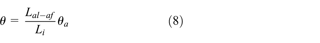
One analytical coordinate system is established, in which the z-axis, which indicates the rotational axis of the gimbal, is perpendicular to the natural horizontal plane. As shown in Figure 2, the centroid of the gimbal is located at
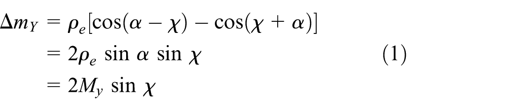
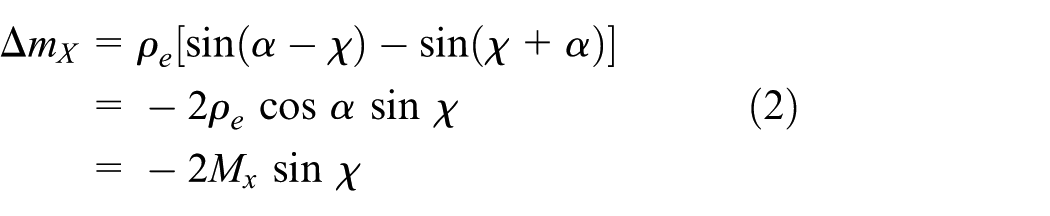
where

Unbalance moment resulting from locomotion of CGP.
Measurement instrument
As shown in Figure 3, the static unbalance measurement system consists of a load platform, flexure-based leverage mechanisms, force sensors, a pneumatic isolating platform, an outer cover and a computer. The load platform is mounted on the pneumatic isolating platform and connects to the flexure-based leverage mechanisms that are assembled vertically. This leverage mechanism conducts the function of the force transmission for a force sensor. The output end of the leverage mechanism is fixed with the force sensor. In this system, the employed force sensor is based on the principle of electromagnetic force balance.24,25 Therefore, the output end of the flexure-based mechanism remains still during force transmission. A computer reads the changes of the force sensors and calculates the static unbalance. The outer cover and pneumatic isolating platform are used to protect the flexure-based mechanism from low-frequency vibration sources, such as wind and sound.
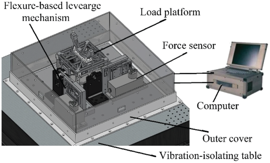
View of the static unbalance measurement system.
Figure 4 shows the double-frame load platform mechanism. The inner frame rotates around the ys-axis in the outer frame, while the outer frame rotates around the xs-axis in the mounting base. The C-Flex pivot bearings are employed as the pivots of the double-frame load platform, which has excellent features, including no static friction torque, no gap, no lubrication and high repeated-use accuracy. Moreover, the fixed part in the load platform is assembled with the input end of the flexure-based leverage mechanism by bolts.

Double-frame load platform mechanism.
The measurement precision of this system is dependent on the sensitivity and precision of the force sensor. The electromagnetic force balance sensor has advantages in terms of sensitivity characteristics and the ratio of the precision to its range. The electromagnetic force balance sensor as the force sensor is valid to improve the measurement precision of the static unbalance measurement system. However, its work range is limited and shorter than other kinds of force sensors.
Flexure-based leverage mechanism
The measure performance of the developed static unbalance measurement system is dependent on the flexure-based leverage mechanism. The objective of the proposed flexure-based leverage mechanism is to transport and adjust the detected force/moment from the load platform into the work range of the force sensor. Therefore, the linearity characteristics in the force transmission of the flexure-based leverage mechanism have significant effects on measuring the unbalance moment of a gimbal.
Figure 5 shows the schematics of the flexure-based leverage mechanism. The developed flexure-based leverage mechanism is divided into two parts. In terms of the mechanical configuration, this leverage mechanism mainly consists of a parallel four-linkage and a two-stage leverage mechanism. The flexure hinges

Schematics of the flexure-based leverage mechanism.
The rigid body
Modelling force transmission
Based on the mechanical properties of the material, the deformation of the flexure hinges is dependent on the applied displacement/force. The kinematic model of the flexure-based leverage mechanism has to be addressed as a function of the deformation strain based on the force/torque equilibrium. In order to simplify calculations and analysis, we assume that the flexure hinge has deformations in only 2 degrees of freedom: the rotational direction and the axial direction. In this analytical procedure, the following assumptions exist:
Deformation only occurs in the flexure hinges. Flexure hinges are regarded as flexible components, while the others are rigid.
Elastic deformation consists of two parts: small angle deflection (rotation angle of less than 1°) driven by a pure moment and small axial strain.
Due to the functional characteristics of the flexible hinges,10–14 the flexure-based leverage mechanism has the capacity to implement the force transmission. During the force transmission, the unbalance moment causes a small deformation at the flexure-based leverage mechanism. Its geometric relationship and topological configuration have a significant influence on the deformation displacement of a flexure-based mechanism. It is essential to model the force transmission of the flexure-based leverage mechanism considering the deformation of the flexure hinges and the self-weights of the rigid bodies. Because the two force transmission paths in the measurement system are the same, we only analyse one.
Right circular flexure hinges
In this work, the proposed flexure-based mechanism only employs the right circular flexure hinge. The right circular flexure hinge is superior to other types of flexure hinges as it is more precise in keeping the positions of the rotation centres during the deformation procedure.11,12 According to the assumptions mentioned above, it ignores the parasitism in the other degrees of freedom while only considering the rotational compliance
Figure 6 shows the geometric relation of the right circular flexible hinge. According to the analysis model in the literature,17,18 the bending compliance and axial compliance of the flexure hinge in the flexure-based leverage mechanism are derived as follows


where R indicates the fillet radius, t indicates the minimum cross-section thickness and h indicates the thickness of the adjacent rigid body.

Schematic of the right circular flexure hinge.
Elastic model
Load platform
According to the CGP measurement concept, because a gimbal placed on the load plane is controlled to rotate at a certain angle, the projected centroid only moves slightly. During the procedure, the flexure bearing in the load platform behaves as a torsional spring. As shown in Figure 7, the moment equilibrium in the load platform is expressed as

where

Schematic diagram of the bearing platform.
The movement of the gimbal’s centroid causes the frame to rotate at a small angle. Before and after the event, equation (5) is reformulated based on a small deformation

where
Flexure-based leverage mechanism
The main function of the flexure-based leverage mechanism is to convert the force/moment from the load platform into the measurable range of the force sensor. The leverage efficiency of the flexure-based leverage mechanism will be affected by the complex deformation. In contrast to other compliant mechanisms, the proposed flexure–based leverage mechanisms are assembled vertically in the measuring system. Hence, the self-weight of components is taken into account in the analytical process.
Figure 8 illustrates the schematic of the leverage mechanism. The parallelogram linkage transports the force from the load frame to the first-stage lever. It has the function of eliminating the parasitical deformation and coupling force in the horizontal direction due to its mechanical configuration. Considering the bending deformation occurring at the flexure hinges, the equation that expresses the moment equilibrium relative to the parallel four-linkage is derived as follows

where
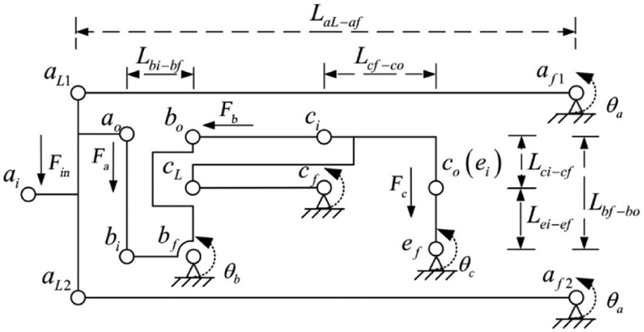
Schematic of the flexure-based leverage mechanism.
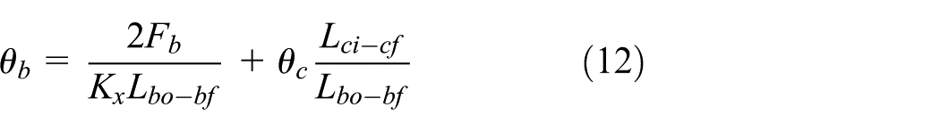
The equation that expresses the bending angle at the parallel four linkages is derived based on the motion as follows
When a force is applied to the first-stage lever, the flexure hinge pivots

where
The equation that expresses the bending angle at the first-stage leverage is derived as follows

The displacement/force is transformed by the linkage arm from the first-stage lever to the second-stage lever along the horizontal direction. The moment equilibrium in the second-stage lever is formulated as follows
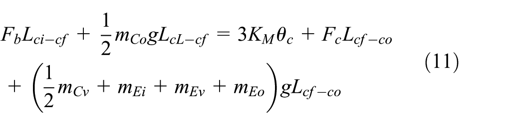
where
The equation that expresses the bending angle at the second-stage leverage is derived as
Combining equations (7)–(12), we obtain the formulations that express the relationships between the output force and the deformation angle in Appendix 1, and the relationships between the output force of the flexure-based leverage mechanism and other forces during the force transmission in Appendix 2.
The force amplification ratio
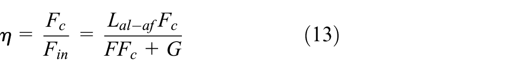
where F and G are expressed in Appendix 2.
Verification and simulation
FEM simulation
FEM is regarded as a valid method for investigating the performance of the flexure-based mechanism in terms of the deformation/force transmission. Because the linearity characteristics of the flexure-based leverage mechanism have a significant impact on the measurement error and precision, it is essential to conduct the static structural simulation subject to various unbalance moments. The mechanical parameters of the flexure-based leverage mechanism are listed in Table 1.
Mechanical parameters of the flexure-based leverage mechanism.

In the simulation, the standard earth gravity was applied while the identical external unbalance was applied step by step. Figure 9(a) depicts the result for the case where the load is 0.04 g in every step, which means that an unbalance moment of 0.32 g cm is added at every step. Figure 9(b) and (c) depicts the resulting curves subject to every step of 0.469 g (3.752 g cm) and 1.41 g (11.28 g cm), respectively. Figure 9(d) combines all results to depict the curves with excellent performance features including linearity and robustness. In terms of the results in Figure 9, the force amplification ratio of the developed leverage mechanism is 0.082 in the ANSYS simulation. Furthermore, the force amplification ratio in the analytical solution is 0.0775. The comparison indicates that the developed analytical solution is a valid method to investigate the flexure-based leverage mechanism. Compared with FEM, the analytical solution is also an easier method to investigate the flexure-based mechanism in terms of time cost.
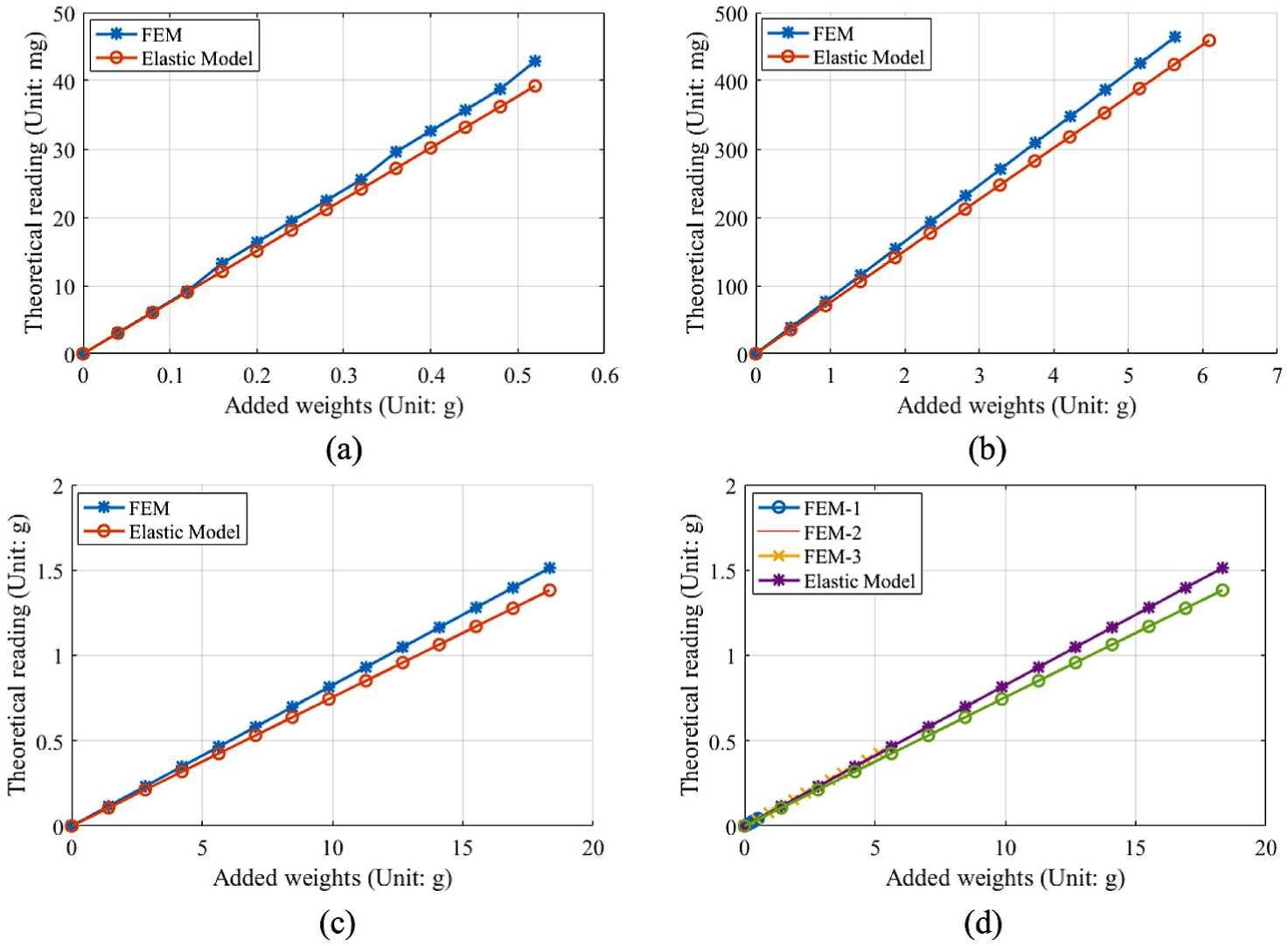
Output force of the flexure-based leverage mechanism subject to various loads.
During the actual static unbalance measurement operation, there was an initial unbalance from the random location of the carrier. The three curves in Figure 10 represent the corresponding reading results under every step of 0.047 g with the initial unbalance at zero, 300 g cm and 600 g cm, respectively. The curves are parallel to each other.
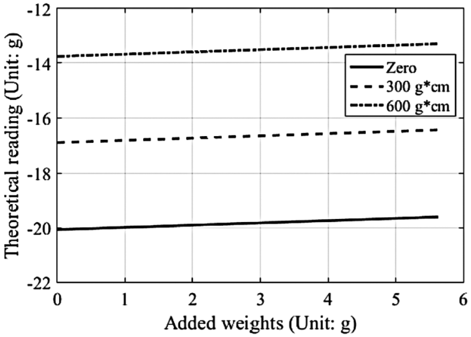
Output force of the flexure-based leverage mechanism under various initial conditions.
As shown in Figure 11, the maximum stress is 20.8 MPa in the flexure hinges, which is far less than the yield strength of 110 MPa; the systematic safety factor is greater than five.

Simulations of stress and deformation in ANSYS.
The natural frequency results for the leverage mechanism using the modal analysis in ANSYS are shown in Table 2. Because the proposed flexure-based mechanism has a low natural modal, it is necessary to employ vibration isolators in the measurement system.
Modal of the flexible mechanism.

Effects of the self-weights
The analytical model was verified by a comparison with FEM in the aforementioned context. The effect of the self-weight of the rigid bodies on the linearity characteristics of the force transmission was investigated based on the analytical solutions. Figure 12(a) shows the output force of the flexure-based leverage mechanism with varying masses of

Relationships between the output force and the self-weights of the rigid bodies: (a) effect of the mass of Av on the output force and the difference in output force, (b) effect of the sum mass of Cv, Ei, Ev and Eo on the output force and the difference in output force, (c) effect of the mass of Bv on the output force and the difference in output force and (d) effect of the mass of Bi on the output force and the difference in output force.
Experimental investigation
Figure 13 demonstrates the overall static unbalance measurement system, without the computer. The systematic mechanism is made of 2A12 aluminium, which has excellent merits including high strength, high elastic modulus, strong yield strength and light weight. The plane dimension of the proposed load platform is 180 mm × 180 mm, and the flexure-based leverage mechanism is 180 mm × 130 mm × 6 mm. The electromagnetic force balance sensors (WZA215 by Sartorius Corp.) have a measurement resolution of 0.0001 g. In the specific experiment, the sensor’s reading was subtracted from the initial reading while varying the proportion of the weights stacked on the single frame. Newport VH Isolation VH3030W was used as a vibration-isolating table. This system is recommended for operation in a room that is not subject to sharp temperature changes and low-frequency vibration sources such as a busy street.

Test system for static unbalance measurement platform.
Unlike the condition in the simulation presented in section ‘Verification and simulation’, the external load was applied not at the input terminal of the flexure-based leverage mechanism but at the load platform Adding a weight of 1 g at the middle point of the outer edge of the load platform resulted in an 8 g cm unbalance moment being applied into either of the freedoms in this system.
The sensitivity is defined as the ratio between the change in measurement to the change in the measure quantity. As shown in Figure 14(a), the maximum hysteresis error was 0.15 g, the sensitivity was less than 0.02 g/(g cm) and the amplification ratio was about 0.0652 in the case where a weight of 5.52 g (44 g cm moment) was used at every step. In Figure 14(b), where weights of 3.62 g are used, the maximum hysteresis error is 0.074 g, the sensitivity is 0.0076 g/(g cm) and the force amplification ratio is 0.0647. Figure 14(c) indicates that the maximum hysteresis error is 0.015 g, the sensitivity is 0.0076 g/(g cm), and the ratio is 0.0613 for weights of 2.84 g. Figure 14(d) indicates that the maximum hysteresis error is 0.016 g, the sensitivity is 0.008 g/(g cm) and the ratio is 0.0606 for weights of 1.41 g.

Experimental data subject to various weights.
As shown in Figure 15, a weight of 0.167 g (1.34 g cm moment) was used to determine the measurement sensitivity at every step. The force amplification ratio is 0.0641, which is close to the results of the aforementioned experiments. Moreover, the measurement linearity performs excellent in terms of the curve. Because the weights are too thin and small to be moved, the experiment on the hysteresis error was cancelled.

Measurement sensitivity experimental results.
Discussion
Force amplification ratio
The ideal force amplification ratio is assumed to be

Within the systematic load capacity, the ideal amplification ratio of the leverage mechanism is about 12.12:1. Because of the energy loss and elastic deformation in the flexible hinges, there must exist a relationship between

According to the simulation, the force amplification ratio by FEM is a little larger than the analytical ratio. This can possibly be caused by the deformation of the rigid bodies of the flexure-based leverage mechanism. From the experimental investigation, the force amplification ratio is smaller than those in both the ANSYS simulation and the theoretical calculation, which is mainly because of the fatigue deformation at the flexure hinges. The difference of the force amplification ratio between the different experiments results from the strain energy of the flexure bearings of the load platform.
Linearity characteristics
The linearity error ratio is defined as the ratio of the maximum hysteresis error to the mass of one weight. According to the experimental investigation, the maximum systemic measure linearity error ratio is 2.72% when a weight of 5.52 g is used. The linearity characteristics of the flexure-based mechanism are affected by the deformation performance of the material. The fabrication and external load make it possible to introduce the residual stress into the mechanism.26,27 Furthermore, the residual stress increases the risk of mechanical failure and fatigue deformation, which affects the linearity characteristics in the displacement/force transmission for a compliance mechanism. However, both the experimental and simulation results verify the robustness of the design of the flexure-based leverage mechanism.
According to the analytical and experimental results, the self-weights of rigid bodies in the flexure-based leverage mechanism significantly affect the output force. However, the flexure-based leverage mechanism retains advanced linearity characteristics in terms of the force transmission. Hence, the measurement result of the static unbalance system is not sensitive to the self-weight of the rigid body. In addition, because the unbalance is determined by the change of the unbalance moment, the measurement system is not affected by the initial constant unbalance conditions in terms of the precision and the linearity characteristics.
Resolution characteristics
The measurement resolution is dependent upon the force sensor in the developed static unbalance measurement system. The systematic measurement resolution is 0.0013 g cm in terms of the static unbalance measure, which is calculated from
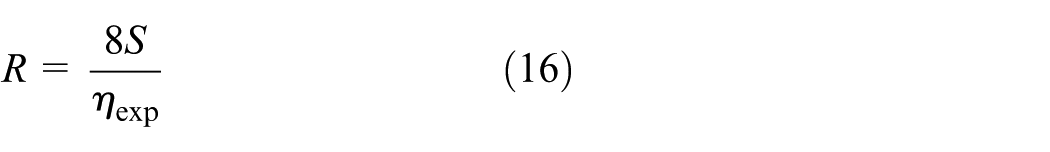
where S is the resolution characteristics of the electromagnetic force balance sensor, and
Conclusion
This article proposes a flexure-based leverage mechanism for a novel static unbalance measurement system. The function of the flexure-based leverage mechanism is to transport and adjust the unbalance moment of the gimbal into the measurement range of the electromagnetic force balance sensor which has merits such as high-level precision and resolution. The force transmission of a flexure-based leverage mechanism was modelled and investigated based on an elastic model. Moreover, we investigated the effects of self-weights of the rigid bodies and the initial constant unbalance on system measurement results and the linearity characteristics of the force transmission of the flexure-based leverage mechanism. A static unbalance measurement system employing the flexure-based leverage had sensitivity of less than 0.02 g/(g cm), maximum linearity error of 2.7%, resolution of 0.0013 g cm and possessed excellent robustness. The flexure-based leverage mechanism is valid to improve the performance of the static unbalance measurement system. This solution can be used in precision engineering applications. The proposed measuring system has been using in the manufacturer. In future work, a solution for eliminating the residual stress will be investigated.
Footnotes
Appendix 1
Appendix 2
Handling Editor: Yangmin Li
Declaration of conflicting interests
The author(s) declared no potential conflicts of interest with respect to the research, authorship, and/or publication of this article.
Funding
The author(s) disclosed receipt of the following financial support for the research, authorship, and/or publication of this article: This work was supported by the National Science Foundation of China (grant no. 51475305).