
Abstract
This article presents a hybrid sensorless speed controller for permanent magnet synchronous motor drives using field programmable gate array technology. The I-f startup strategy is applied to permanent magnet synchronous motor drives at the startup condition and then it will smoothly switch to extended Kalman filter–based sensorless field-oriented control at the adequate condition. The I-f startup is a simple strategy and suitable for the low-speed sensorless control without initial rotor position estimation and machine parameters estimation. Meanwhile, the extended Kalman filter–based sensorless field-oriented control is appropriate for the medium- and high-speed sensorless control. Therefore, combining two approaches, the sensorless permanent magnet synchronous motor can be smoothly operated from a standstill to a high-speed condition. In this article, first, the mathematical modeling of permanent magnet synchronous motor is introduced. Also, the I-f startup strategy is conducted, and the rotor position estimation algorithm by extended Kalman filter is derived. Second, a very high-speed integrated circuit hardware description language is presented to describe the behavior of the adopted estimation and control algorithm. This application codes have been confirmed using Simulink and ModelSim co-simulation. Finally, a field programmable gate array–based experimental system is utilized to verify the correctness and effectiveness of the proposed hybrid sensorless speed controller for a permanent magnet synchronous motor and a ceiling fan motor.
Keywords
Introduction
In recent years, permanent magnet synchronous motor (PMSM) has significantly attracted the attention of researchers due to its simplicity of design, the ability of operation at wide range speeds, high efficiency, and high power/torque density. Hence, it has been increasingly used not only in several industrial sectors but also in household appliance and electrical vehicle applications.1–4 However, a conventional PMSM control needs a sensor to measure the rotor position and rotor speed for ensuring the precision field-oriented control (FOC) and speed control, but such sensor presents some disadvantages such as drive cost, machine size, reliability, and noise immunity.
Sensorless speed control for PMSM drive has become popular in research topics in the literature.4,5–15 It can be categorized into un-model-based approach and model-based approach. The former approach, such as the high-frequency signal injection (HFSI),5–8 is suitable for low-speed running or standstill condition of PMSM. The latter approach has back electromotive force (BEMF), sliding mode observer (SMO),9,10 and extended Kalman filter (EKF),4,11,12 which are suitable for medium- or high-speed running condition of PMSM. The EKF is a full-order stochastic observer for the recursive optimum state estimation of a nonlinear dynamic system in real time using signals that are in the noisy environment. Comparing with SMO, EKF can directly estimate the angular speed, and it has high convergence rate which can give more rapid speed response. 4 However, due to the small back-EMF signal at low and near to zero speed condition, EKF estimator loses its ability to produce accurate position and speed estimation.
HFSI is one solution to solve the startup problem; however, it is complicated in signal processing and easily causes an acoustic problem. Therefore, in the literature, a simple startup strategy is reported, well-known as V-f and I-f method.13–15 The full name of the V-f is voltage–frequency. The name of I-f is mapped from V-f startup method. However, instead of specifying a voltage reference in the V-f control, the current in the I-f control is specified. The V-f control is an open-loop control scheme with no current feedback in implementation. When it applies to PMSM, the motor may lose its synchronization and get unstable. As a result, the operation may not be successfully switched especially in external load conditions. To counter these problems, this article proposes that the system should be equipped with the current closed-loop control that is commonly referred to I-f control. The strategy of I-f startup solution is suitable for the low-speed sensorless control systems without initial rotor position estimation and machine parameters estimation algorithms.14,15
Recently, a co-simulation work by electronic design automation (EDA) Simulator Link has been applied to verify the effectiveness of hardware description language (HDL) code in the motor drive system.16,17 The EDA Simulator Link provides a co-simulation interface between Simulink and HDL simulators, ModelSim. EDA Simulator Link enables to use MATLAB code and Simulink models as a test bench that generates stimulus for an HDL simulation and analyzes the simulation’s response. In this article, a co-simulation by EDA Simulator Link is applied to the EKF-based sensorless PMSM speed control with I-f startup. The PMSM, inverter, current and speed command, and I-f startup strategy are performed in Simulink while the FOC, EKF, proportional and integral (PI) speed controller, space vector pulse width modulation (SVPWM), and coordinate transformation described by very high-speed integrated circuit (IC) hardware description language (VHDL) code are executed in ModelSim. The effectiveness of the motor operation from I-f startup then switching to the sensorless FOC for PMSM drive will firstly validated by simulation.
In realization, both digital signal processor (DSP) and field programmable gate array (FPGA) can provide a solution to this issue. Due to the advantages of fast and parallel computation ability, programmable hard-wired feature, low power consumption, shorter design cycle, embedding processor, and higher density, FPGA is better than DSP and becomes the most popular IC in the implementation of the complex computation of the digital estimator or controller system.18,19 Therefore, in this article, based on the FPGA technology, a realization of a hybrid sensorless controller using I-f startup and EKF is applied in PMSM drive, and it is shown in Figure 1. The FOC, EKF, PI speed controller, SVPWM, and coordinate transformations described by VHDL code are implemented in digital hardware of FPGA. The code of the speed command, and the switching strategy from startup to the FOC sensorless are developed by C language and realized in Nios II processor. Experimental results with a PMSM or a fan motor will prove the success of the proposed approach in the sensorless PMSM drives.
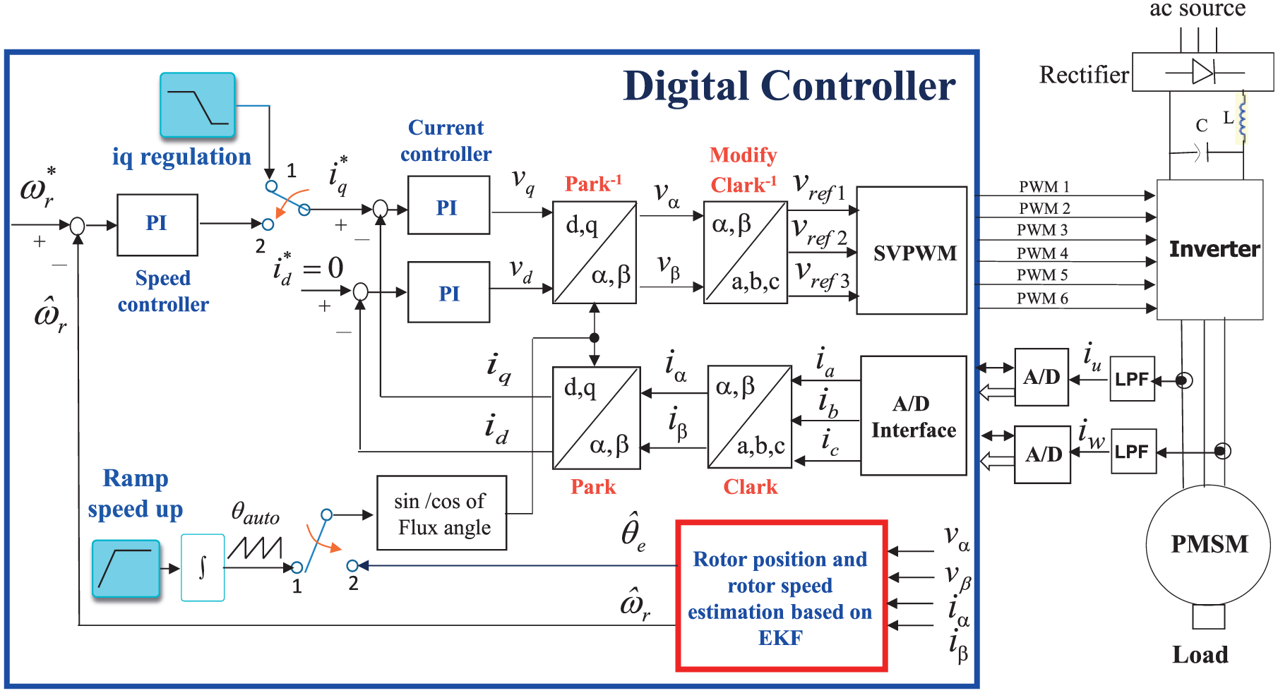
The architecture of a hybrid sensorless control for PMSM drive with the I-f startup and the EKF-based estimator.
System description of PMSM drive and the hybrid sensorless speed control
The hybrid sensorless speed control block diagram for PMSM drive with I-f startup is shown in Figure 1. It consists of two control modes: the first mode is I-f startup mode and the second mode is sensorless FOC mode which is based on an EKF estimator. These two modes are activated by two switches. For the I-f startup mode, the switches are connected to terminal 1, and for the EKF-based sensorless FOC mode, the switches are connected to terminal 2. The detailed formulations regarding the modeling of PMSM, the startup strategy, and the EKF-based rotor position and rotor speed estimation are introduced as follows.
FOC
The mathematical model of a PMSM is described in two-axis d-q synchronous rotating reference frame, as follows
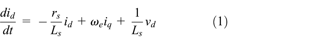
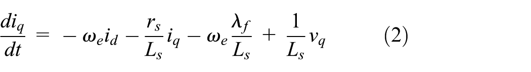
where vd, vq are the d and q axis voltages; id, iq are the d and q axis currents; rs is the phase winding resistance; Ls = Ld = Lq and Ld, Lq is the d and q axis inductance;
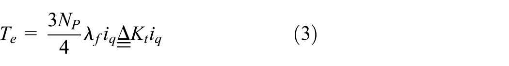
Considering the mechanical load, the overall dynamic equation of a PMSM drive system is obtained by

where Te is the motor torque,
EKF-based estimator
Transforming (1) and (2), the mathematical stochastic nonlinear model of a PMSM on the


where


where


After the discrete model of the motor stochastic nonlinear equation is obtained, the EKF algorithm can be used to estimate the state value of
Step 1: (Prediction step)
Using a simple rectangular integration in equation (5)

The covariance is updated by

Step 2: (Innovation step)


The Kalman gain is calculated by
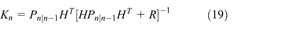
where
I-f startup strategy
I-f startup strategy bases on the closed-loop current controller architecture. To make it able to switch to the sensorless FOC smoothly, controlling the current value in q*-axis and the angular frequency
Step 1: Speed ramp-up with constant regulation at first start. This step aims to allow the back-EMF (electromotive force) signal to be sensed properly on appropriate motor acceleration to obtain the accurate rotor position and speed information. The current command

Step 2: The constant speed with decreasing q*-axis current at

Step 3: Switching to the EKF-based sensorless FOC mode operation at the end (
Where
Design of a sensorless speed controller intellectual property
Figure 2 illustrates the internal architecture of the proposed FPGA implementation of a hybrid sensorless speed control intellectual property (IP) using I-f startup and EKF for PMSM drives. The internal circuit contains a Nios II embedded processor IP and an application IP. The Nios II processor IP is functioned to generate the speed command (

Internal architecture of a sensorless speed control IP in FPGA.

The work in Nios II processor—the sequential process control and the speed command generation.
The sampling frequency of the speed control loop, current control loop, and EKF estimator are designed with 2, 16, and 16 kHz, respectively. The frequency divider generates 50 MHz (Clk_20ns), 12.5 MHz (Clk_80ns), 5 MHz (Clk_200ns), and 2.5 MHz (Clk_400ns) clock to supply all circuits in Figure 2. The data type in the circuit of the speed loop PI controller and EKF estimator uses 16-bit Q15 format, and others circuits are 12-bit Q11 format. All circuits adopt two’s complement operation. The FPGA herein adopts an Altera Cyclone IV-EP4CE115 which has 114,480 LEs (logic elements), 3,981,312 RAM bits, and 150 embedded 9-bit multipliers inside. The multiplier, adder, and divider apply the standard Altera LPM (library of parameterized module). In this section, digital hardware realization of PI speed controller, CCCT, and EKF-based rotor position and rotor speed estimation are discussed.
The internal circuit of CCCT is shown in Figure 4, which performs the function of two PI controllers, lookup table for sine/cosine function, and the coordinate transformation for Clark, Park, inverse Park, modified inverse Clarke. All of these components will operate continuously and simultaneously. To reduce the resource usage in FPGA, the designed CCCT circuit adopted using the finite state machine (FSM) method is proposed and shown in Figure 4, which uses one adder, one multiplier, a 1-bit left shifter, a lookup table and manipulates 24 steps machine to carry out the overall computation of CCCT. The data type is the 12-bit length and Q11 format. In Figure 4, step s0–s1 is for the lookup table; step s2–s4 and s5–s7 are for the computation of d-axis and q-axis PI controller, respectively; and steps s8–s12, s13–s16, s16–s18, and s19–s23 represent the transformation of inverse Park, modified inverse Clarke, Clarke, and Park, respectively. The system clock in Figure 4 is 80 ns; therefore, total 24 steps, it needs only 1.92 μs operation time. Moreover, the speed loop PI controller designed using FSM is shown in Figure 5, and it manipulates seven steps machine to carry out the overall computation. In Figure 5, steps s0–s1 execute the I controller; step s2 calculates the speed error; step s3 limits the speed error within ±500 r/min; steps s4–s6 perform a P controller and send out the current command. The Kp and Ki are the PI controller gains of the speed loop. The data type adopts 16-bit with the Q15 format and two’s complement operation. In Figure 5, total seven steps need 0.56 μs operation time. Finally, the similar method of FSM is employed to illustrate the EKF computations.

The internal circuit of CCCT for digital hardware realization.
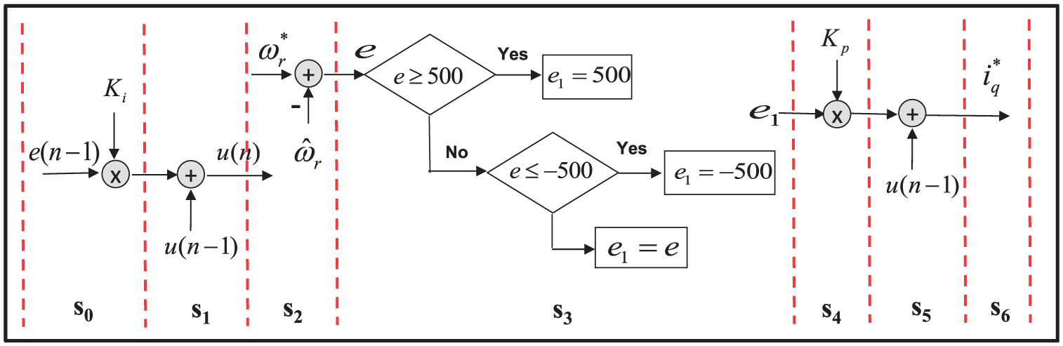
State diagram of speed loop PI controller.
The design result is shown in Figure 6 which mainly uses one adder, one multiplier, one divider, two sin/cos lookup tables, and so on, and manipulates 131 steps machine to carry out the overall computation. The numerical data type adopts 16-bit length with Q15 format and two’s complement operation. The multiplier and adder apply the standard Altera LPM. In Figure 6, steps s0–s12 execute the calculation of the Jacobian matrix and predict temporary state variables; steps s13–s68 perform the computation of temporary covariance matrix; steps s69–s70 are for state error calculation; steps s71–s120 update of the present covariance matrix Pn and calculate the Kalman gain Kn; steps s121–s130 describe the present state tuning as well as execute the computation of rotor position and rotor speed. The operation of each step in Figure 6 is 80 ns (12.5 MHz) in FPGA; therefore, total 131 steps, it needs only 10.48 μs operation times.

The state diagram of FSM for illustrating the EKF computations.
Finally, the FPGA utility of the proposed sensorless control IC for a PMSM drives in Figure 2 is evaluated, and the result is listed in Table 1. It shows that the overall circuits of the proposed sensorless control IC include a Nios II embedded processor IP (7433 Les, 75,904 RAM bits, and 4 embedded 9-bit multiplier) and an application IP (10,271 Les, 210,917 RAM bits, and 24 embedded 9-bit multiplier), which uses 15.46% of the LEs resources, 7.20% of the RAM resources, and 18.67% of the embedded 9-bit multiplier for a Cyclone IV-EP4CE115.
The FPGA utility of the proposed sensorless control IC for a PMSM drives.

IP: intellectual property; EKF: extended Kalman filter; PI: proportional and integral; SVPWM: space vector pulse width modulation; ADC: analog-to-digital converter.
Simulink/ModelSim co-simulation and its simulation results
Figure 7 presents the ModelSim/Simulink co-simulation architecture of the proposed hybrid sensorless speed control system for PMSM drive with I-f startup and EKF estimator. The SimPower System blockset in the Simulink executes the PMSM and the insulated-gate bipolar transistor (IGBT)-based inverter.I-f startup strategy, speed command, and PI controller parameters setting are performed in Simulink.
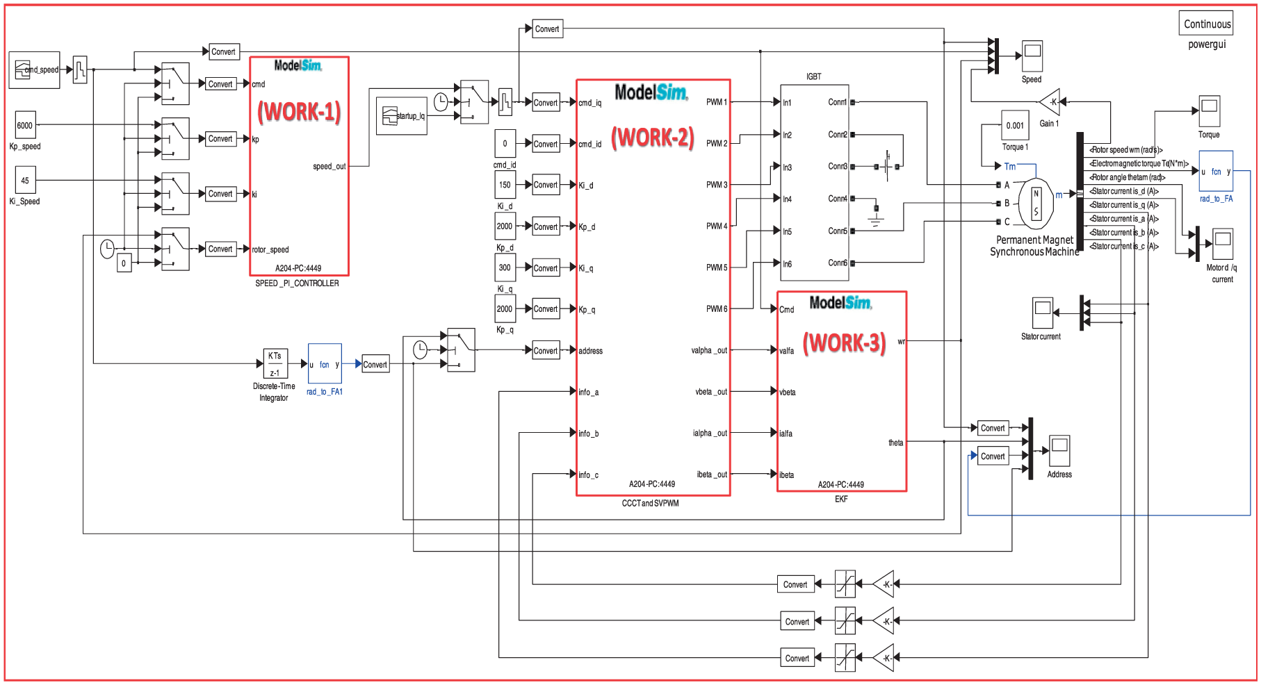
The ModelSim/Simulink co-simulation architecture of the proposed hybrid sensorless speed control system for PMSM.
The EDA simulator link for ModelSim executes the co-simulation using VHDL code in the ModelSim program. It executes the function of the sensorless speed controller by three works. The work-1 performs the speed loop PI controller; work-2 performs the FOC which includes the current PI controller, coordinate transformation, and SVPWM generation; and work-3 performs the EKF-based rotor position and rotor speed estimator. The sampling frequency in the current control loop and the EKF-based estimator is designed with 16 kHz but in speed control loop is 2 kHz. All works (work-1, work-2 and work-3) are performed by ModelSim and the external clocks are supplied by 50 MHz and 12.5 MHz. In this simulation, the PMSM model parameters used in Figure 7 are that pole pairs are 4, stator phase resistance is 1.3 Ω, stator inductance is 6.3 mH, inertia is J = 0.000108 kg m, and friction factor is F = 0.0013 N m s. The PI gains are designed with Kp = 0.183 and Ki = 0.0013.
In the simulation, the system is first operated at the I-f startup mode and then switched to the EKF-based sensorless FOC mode when the time is at 0.28 s. At the first stage of the startup mode, the current command
Additionally, the PMSM running from the low to medium-speed (200 r/min → 400 r/min → 600 r/min) condition and at the inverse speed (from 200 r/min to −200 r/min or vice versa) condition in this stages are considered. Under the above-designed operation state, the simulation results of the speed, current, and position response for the PMSM drive are presented in Figures 8 and 9. From the results in Figures 8 and 9, it can be noted that the rotor speed response tracks the auto-generated speed command with severe oscillation at the I-f startup mode; meanwhile, the condition is improved after the control strategy is switched to the EKF-based sensorless FOC mode which the actual rotor speed can smoothly track the speed command with fast transient response (rising time = 0.025 s). The results show a little overshoot (maximum about 6%) and near zero steady-state error. It also shows that EKF speed estimate can keep tracking the actual rotor speed very well. Furthermore, the current responses in Figures 8 and 9 indicate that the current in d-axis can be controlled near to zero and the measured current in d-q axis can track the current command well, which reveals the success of the FOC strategy and the performance of the closed-loop current controller.
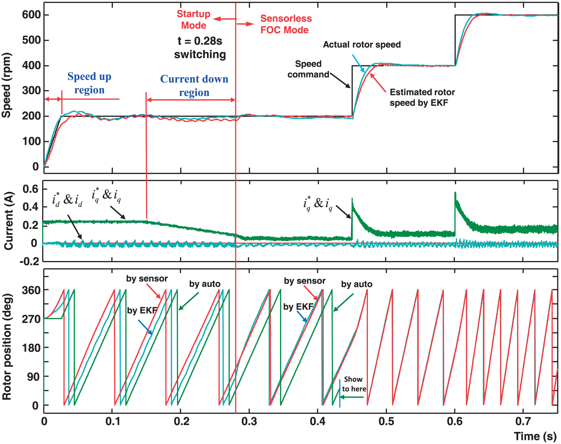
Speed, current and position response for PMSM drive from the startup to the medium-speed running condition.
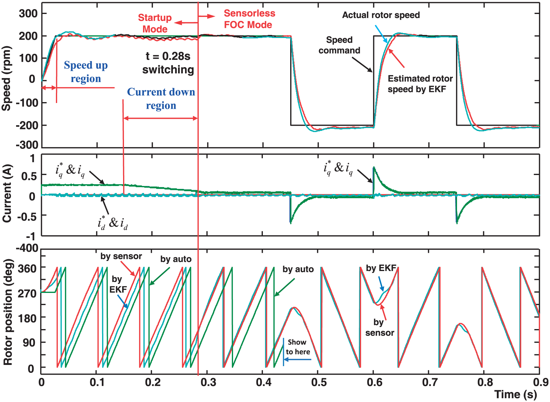
Speed, current and position response for PMSM drive from the startup to the inverse speed running condition.
Finally, the rotor position detected by auto-generation, measured by a sensor (that is represented with the synchronously rotating reference), and estimated by EKF are discussed herein. At the I-f startup mode, the PMSM is driven by the auto-generated rotor position command which the speed value starts from 0 r/min and then increases to 200 r/min. Before the current down region (the q-axis current
Experimental system and results
After confirming the correctness of the proposed I-f startup and EKF-based sensorless control IP by simulation, the VHDL codes directly apply to the experimental FPGA-based sensorless PMSM drive system. The block diagram and real experimental system are presented in Figure 10. The experimental system equips with a PMSM, a DE2-115 board with Altera Cyclone-IV FPGA, an intelligent power module (IPM)-based driver, and a power supplier. The parameters of the PMSM are rs = 0.63 Ω, L = 2.77 mH, and four pole pairs. The input voltage, continuous current, rating torque, rating speed, and continuous power of the PMSM are 220 V, 12 A, 2.3 N m, 3000 r/min, and 750 W, respectively. Inside the IPM, it has six sets of IGBT type power transistors with a rated voltage of 600 V, collector DC rating of 20 A, and a short-time (1 ms) rated current of 40 A.

Experimental system by (a) the overall block diagram and (b) the real system.
The FPGA adopts Cyclone IV-EP4CE115 which is the product of Altera Corporation. The Cyclone IV-EP4CE115 has 114,480 LEs (logic elements), 3,981,312 RAM bits, and 150 embedded 9-bit multipliers. Also, a Nios II processor with 32-bit CPU and flexibility of core size can be embedded into the FPGA to establish a system on a programmable chip (SoPC) environment. Therefore, in Figure 10, the proposed internal circuit in the FPGA contains a Nios II embedded processor IP and an application IP. The former performs the function of the speed command generation and the three steps sequential control from I-f startup mode to sensorless FOC mode. All programs in Nios II processor are coded in the C language. The latter includes mainly a circuit of the speed PI controller, a circuit for FOC, a circuit of an EKF-based estimator, an SVPWM circuit, and an ADC interface circuit. All circuits are described by VHDL code and constructed with hardware in FPGA. The operating clock of the designed FPGA controller is 50 MHz. The PI gains in the speed loop are designed with Kp = 0.854 and Ki = 0.0007. The sampling frequency in position, speed, and current control loop are designed with 2, 2, and 16 kHz, respectively.
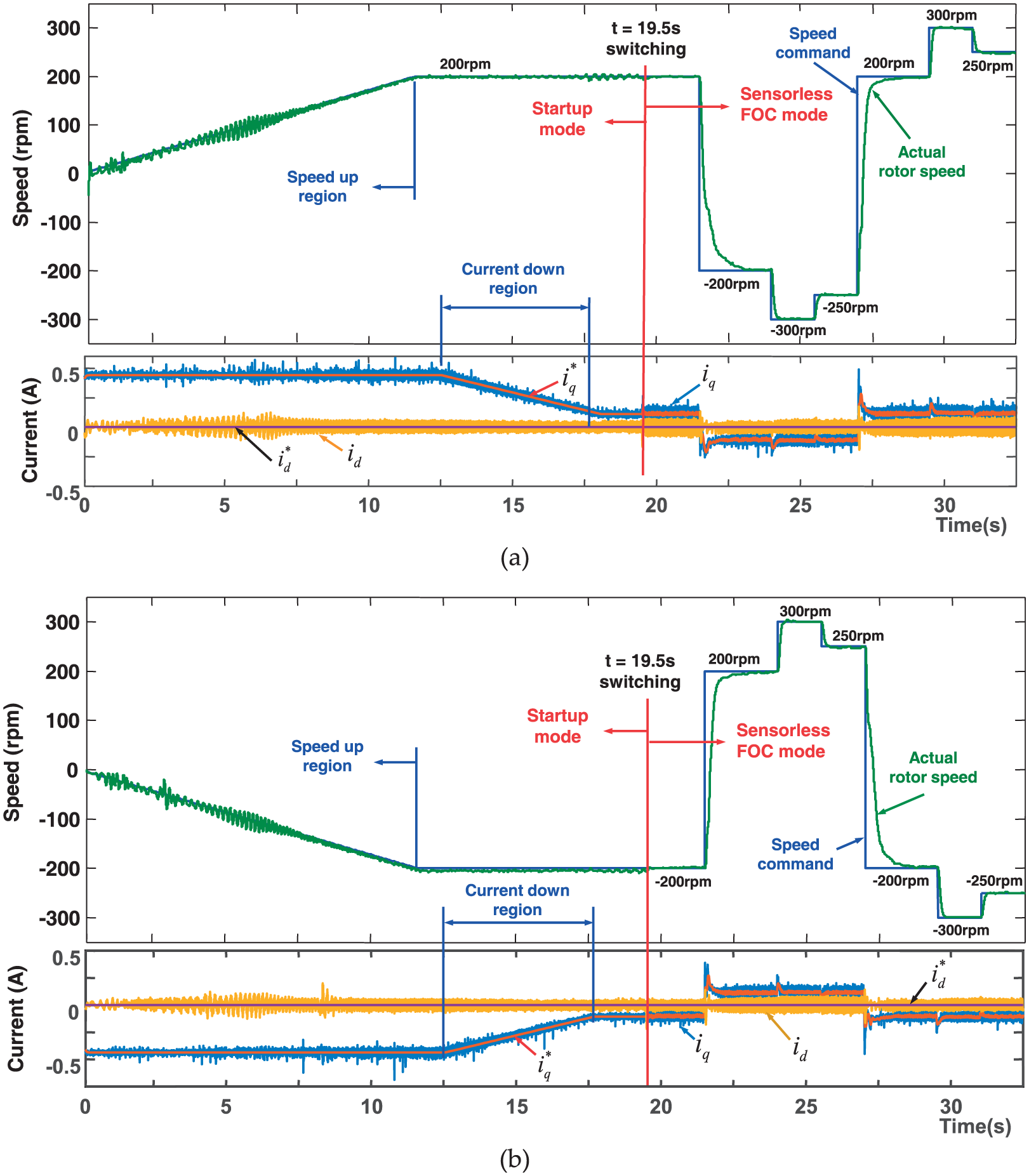
In the implementation, the PMSM is first operated at the I-f startup mode; then it will be switched to the EKF-based sensorless FOC mode when the time is at 19.5 s. At the first stage of the startup mode, the current command

Speed and current response for PMSM drive from the I-f startup to EKF-based sensorless FOC in the wide range speed condition.

Rotor speed and rotor position for PMSM drive in the I-f startup mode.
The rotor speed response in Figures 11 and 12 reveals that the actual rotor speed follows the speed command with a severe oscillation at the I-f startup mode, but it will smoothly track the speed command with a fast transient response (rising time = 0.18–0.2 s), a little overshoot (maximum about 3%–4%), and near zero steady-state error after it switches to the EKF-based sensorless FOC mode and runs to the high-speed condition. The d-q axis current response in Figure 11 presents that the measured current in d-q axis can track the current command well. It also shows that the current in d-axis can be controlled near to zero in the EKF-based sensorless FOC mode which exhibits the success of the FOC strategy.
The rotor position response in Figure 12 presents that before the current fall down region occurs (the q-axis current
In Figure 13, among the actual rotor speed, speed command and the EKF-based estimated rotor speed, it presents some fluctuation error (about −6 to +12 r/min) at low-speed (200 r/min) condition and small bias (about −5 to +5 r/min difference) at high-speed (800 or 1600 r/min) condition. Figure 13 also shows that the rotor position estimated by EKF will fluctuate to track the rotor position measured by the sensor with a phase difference by 10.1° at low-speed (200 r/min) condition, but smoothly track with only a phase difference by 5.2° at high-speed (1600 r/min) condition. Besides, under the ±200 r/min speed command in the sensorless FOC mode, the rotor speed and rotor position tracking results are shown in Figure 14, which presents a fast speed tracking with 36 ms rising time, no overshoot condition occurred, and near zero steady-state error (within 5 r/min). This result also shows the estimated rotor position by EKF can follow the actual rotor position by sensor very well in the positive or negative speed command. Therefore, the results in Figures 13 and 14 confirm that the estimated rotor speed and rotor position have larger errors compared to the measured value at low-speed condition than at high-speed condition. This is because the acquisition signals in currents and voltages are weak and easily contaminated by the external noise at this condition. However, any speed command larger than 200 r/min under sensorless FOC can get a good rotor speed control and rotor position estimation in the proposed system.
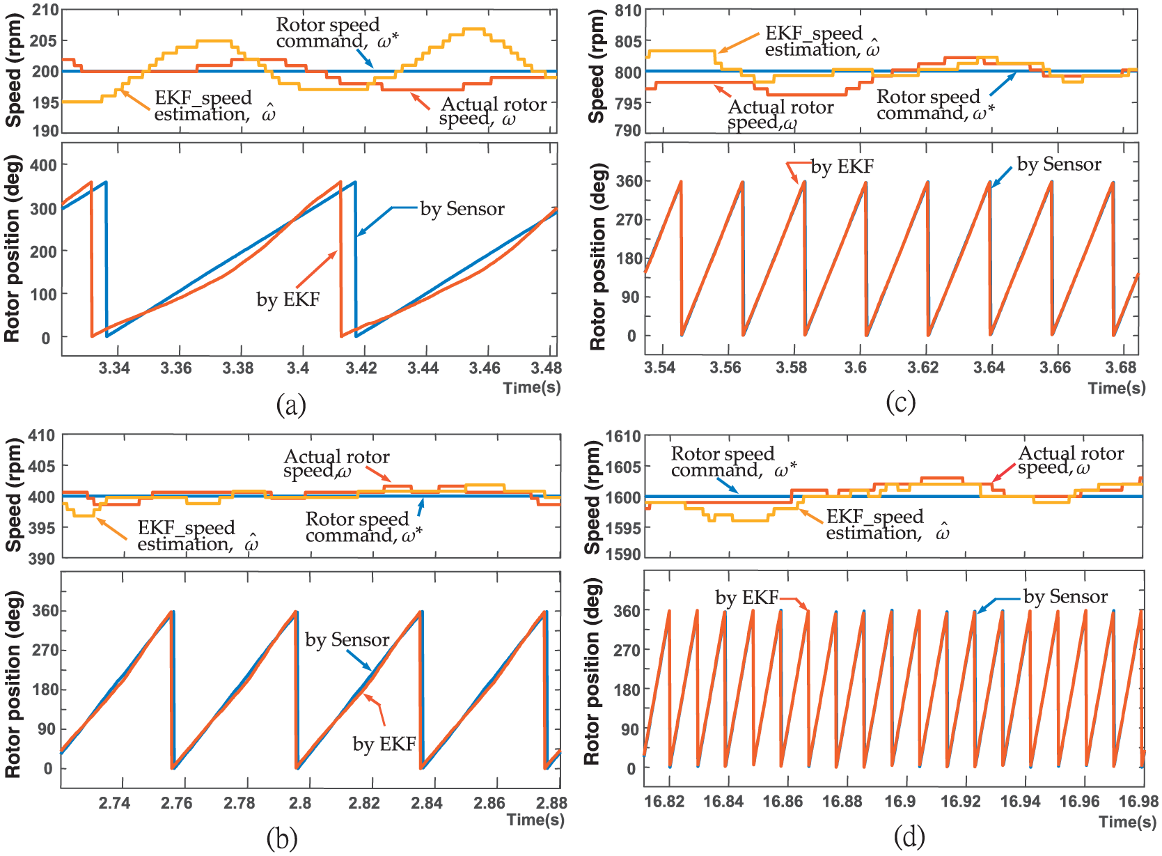
Rotor speed and rotor position performance in steady-state condition under the speed command with (a) 200 r/min, (b) 400 r/min, (c) 800 r/min, and (d) 1600 r/min.
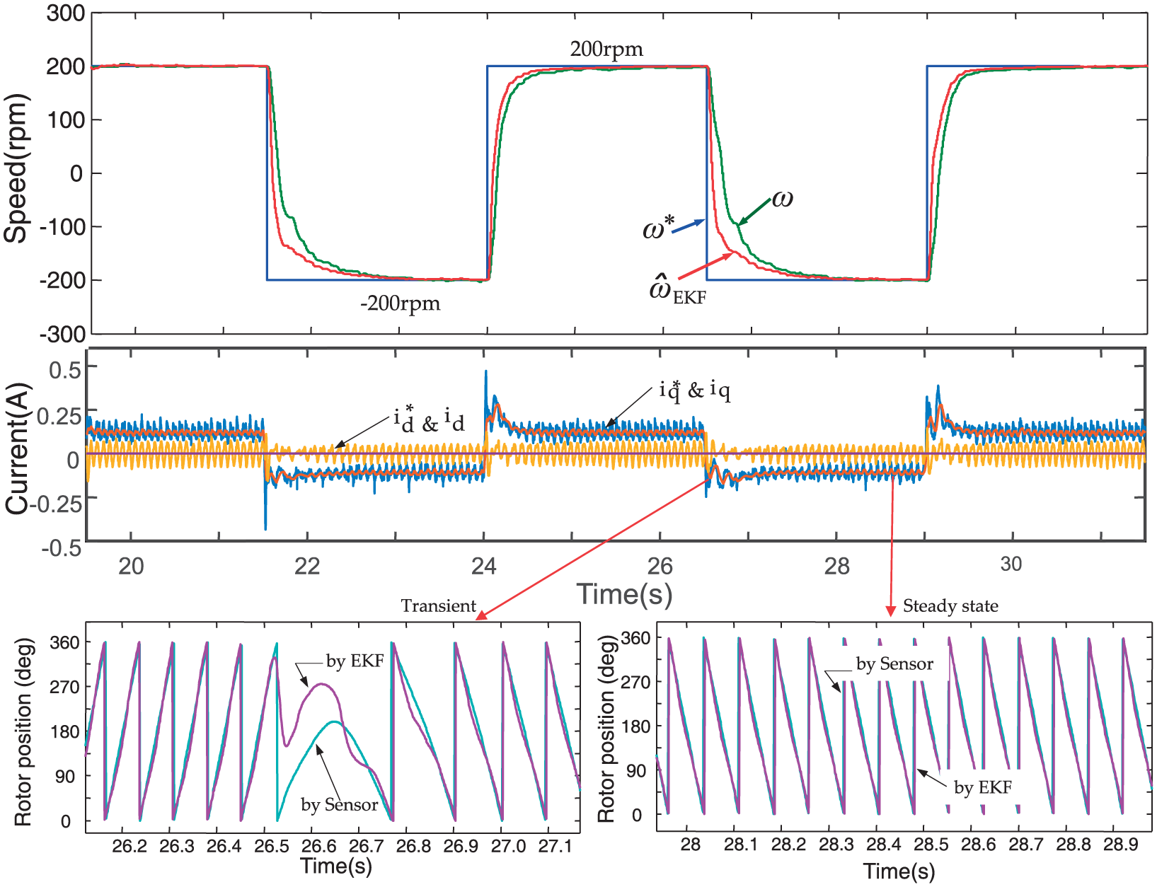
Rotor speed and rotor position tracking response under the inverse speed command with ±200 r/min.
Furthermore, PMSM drives operated from standstill to clockwise rotation and from standstill to counterclockwise rotation using the proposed approach are investigated. During the startup mode, the former needs a positive I-f startup which will generate a positive q-axis current command, and the latter is a negative I-f startup with a negative q-axis current command. The experimental results from the positive I-f startup or the negative I-f startup to the sensorless FOC are shown in Figure 15. It can observe that the overall tracking responses in the actual rotor speed and in the d-q axis current loop are having good performances as well as the results in Figure 11. Figure 15 also confirms that the PMSM can be operated directly from the positive speed (minimum with 200 r/min) to the negative speed (maximum with the −200 r/min) or vice versa in the sensorless FOC mode. However, if the PMSM needs to be controlled within under the ±200 r/min or at the standstill condition, it is better to switch the control mode to the I-f startup mode.
Rotor speed and current response for PMSM drives which is controlled from (a) the positive I-f startup mode or (b) the negative I-f startup mode, to the EKF-based sensorless FOC mode.
To consider the external load effect on the proposed system, another plant by a ceiling fan motor (outer-rotor PMSM) is tested, and the experimental system is shown in Figure 16. Except for the ceiling fan motor, other devices are the same with the experimental system in Figure 10. The parameters of the ceiling fan motor are rs = 49.57 Ω, L = 467 Mh, and 8 pole pairs. The input voltage, rating torque, operating speed range of the ceiling fan motor are 88.8 V, 1.4 N m, 0–230 r/min, and 300 W, respectively. An infrared IR-Tachometer was attached to the ceiling fan motor for measuring the actual rotor speed. The specification of the tachometer is LUTRON DT-2230. Similar to the previous experimental design, the ceiling fan motor will be operated at the I-f startup mode; then it will be switched to the EKF-based sensorless FOC mode. The switching time is at 95 s and the switching speed is set at 60 r/min. During the I-f startup mode, the iq current command is first fixed to 0.336 A and the speed command is gradually increased to reach the switching speed with 60 r/min; then the speed command is held, and the iq current is decreased from 0.336to 0.05 A. After switching to the EKF-based sensorless FOC mode, the speed command is set from 60 r/min → 80 r/min → 120 r/min → 160 r/min. Under the designed operation, the experimental results of the speed and current response, as well as the rotor position response for the drive of the ceiling fan motor, are shown in Figures 17–19.Figure 17 presents that the I-f startup strategy can successfully force the rotor running from standstill to 60 r/min and switch to the EKF-based sensorless FOC mode for running to the medium-speed condition. The experimental result in tracking the performance of the medium-speed condition presents a speed tracking with 11 s rising time, 20% overshoot occurred, and near zero steady-state error (within 2 r/min). Moreover, the d-q axis current response in Figure 17 reveals that the measured current in d-q axis can track the current command well. It also shows that the current in d-axis can be controlled near to zero in the EKF-based sensorless FOC mode which exhibits the success of the FOC strategy. Similar to Figure 12, Figure 18 presents the rotor position of the ceiling fan motor on I-f startup condition. The phase lead angle between measured by auto and estimated by EKF reduced from 96° down to 60° which let the switching operation from I-f startup mode to the sensorless FOC mode smoothly. Figure 19 demonstrates the speed and rotor position performances in steady-state condition under the variable speed command at 60, 80, 120, and 160 r/min. It shows a good performance that the steady-state errors are within 2 r/min. From Figures 17–19, it shows that the proposed system is robust under an external load effect. Finally, from the experimental results in Figures 11–15 and 17–19, it verifies that the proposed FPGA-based sensorless speed control IC using I-f startup and EKF-based sensorless FOC is to an effective and correct.

Experimental system for speed control of a ceiling fan motor (it is without position sensor).
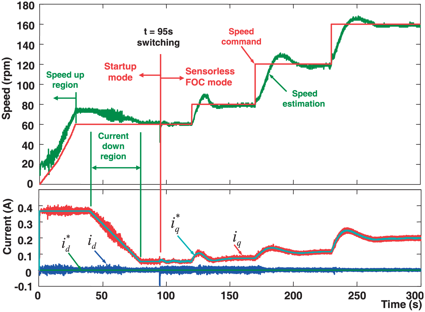
Speed and current response for the ceiling fan motor from the I-f startup to the EKF-based sensorless FOC.
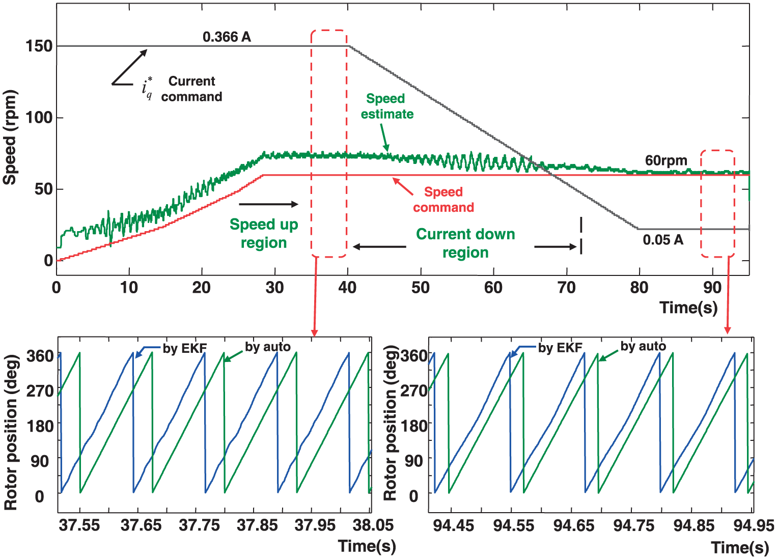
Rotor speed and rotor position for the ceiling fan motor in the I-f startup mode.

Speed and rotor position performances in steady-state condition under the speed command with (a) 60, (b) 80, (c) 120, and (d) 160 r/min.
Conclusion
An FPGA-based hardware-software co-design solution to implement a sensorless controller for PMSM drive, which is based on the I-f startup and EKF technology, is successfully demonstrated in this article. The works herein are summarized as follows:
An I-f startup strategy and speed command are implemented in software using a Nios II embedded processor, as well as the PI controller, the FOC and the EKF-based estimator are implemented in hardware by FPGA. The software/hardware co-design technology with parallel processing has significantly improved the system performance. Additionally, the functionalities required to build a hybrid sensorless speed controller are realized using only one FPGA chip.
Simulink/ModelSim co-simulation and FPGA-based experimental results have confirmed that no matter either a positive or negative rotation startup is applied; the employed I-f startup strategy can smoothly switch to the EKF-based sensorless FOC with near 100% successful rate.
The experimental results have confirmed that the EKF-based realization of the sensorless controller can boost up the speed and precisely control the actual rotor speed if the speed command of PMSM is large than 200 r/min or less than −200 r/min. Out of this speed range (within ±200 r/min), the acquisition signals in currents and voltages of PMSM are weak and easily contaminated by the external noise which will cause an estimated rotor position error in the EKF-based estimator.
The combination of two approaches with I-f startup and EKF, a PMSM and a ceiling fan motor can be operated well and employed at wide range speed applications.
Footnotes
Acknowledgements
The authors also gratefully acknowledge the support of Green Energy and Environment Research Laboratories, Industrial Technology Research Institute, Taiwan.
Handling Editor: Artde Lin
Declaration of conflicting interests
The author(s) declared no potential conflicts of interest with respect to the research, authorship, and/or publication of this article.
Funding
The author(s) disclosed receipt of the following financial support for the research, authorship, and/or publication of this article: This study was financially supported by the Bureau of Energy, Ministry of Economics Affairs of Taiwan.