
Abstract
Mechanical models of deceleration meshing pair and equal-speed meshing pair are derived using the rigidity coefficient and static equilibrium conditions of plate (fixed plate, output shaft, or plane plate). The elastic angles are obtained, and their manner of variation is analyzed. With the variation in system parameters, the manner of variation in the whole elastic angle of a cycloid ball planetary transmission is studied. For different axial pretightening forces, the variation in the whole elastic angle is tested with increase in torque, and the experimental test values are compared with those calculated theoretically. The results show that a necessary and sufficient condition for continuous transmission of a cycloid ball planetary transmission is to load the larger of the maximum values of the minimum axial pretightening forces of the deceleration and equal-speed meshing pairs. For fixed parameter values, the elastic angle of the ring-groove equal-speed meshing pair is smaller than that of cross-slide-groove. With increase in the short amplitude coefficient, the axial pretightening force, and the rolling-circle radius, the whole elastic angle decreases. With increase in the angle between the common normal line and the plate plane (β), the whole elastic angle increases. The experimental results validate the correctness of the elastic angle mathematical model.
Keywords
Introduction
Adopting a cycloid gear shape improves the transmission performance of both the gear drive mechanism 1 and the movable-teeth transmission mechanism.2,3 A cycloid ball planetary transmission (CBPT) uses a cycloid to conduct the meshing transmission, and both the deceleration and equal-speed meshing pairs use the no-backlash meshing technique formed by a no-backlash meshing pair. Therefore, this type of drive mechanism has become a very important high-performance transmission mechanism, with characteristics such as no-backlash transmission, high meshing efficiency, low noise, and a compact structure that is apt for micro-miniaturization. These outstanding characteristics make the CBPT an invaluable and promising prospect in the field of high-precision transmission, such as a transmission mechanism for compensating the displacement of an airborne remote-sensing camera, and robot servo drive mechanism reciprocating grasping of workpiece frequently.
CBPTs have been widely studied for many years. In 1988, the structure and transmission principle of a new type of CBPT were introduced, showing that this type of reducer has linear characteristics. 4 In 1990, several factors affecting the design of the mechanism were analyzed, such as the radius of curvature and the pressure angle. From that analysis, it is known that there is an optimal value of the trochoid factor that affects the radius of curvature and pressure angle. 5 In 1995, the fundamental design parameters of the CBPT were derived and investigated, and the strength of the cycloid groove of this reducer was analyzed using Hertz’s theory. 6 In 1996, the formation of the CBPT and its transmission principle were analyzed, given the transmission-ratio equation and dynamic equilibrium condition, and the meshing technology was studied. 7 In 1997, a new type of efficiency-calculation method was used to optimize the parameters of the CBPT. A new type of output mechanism was designed and studied. 8 In 2009, the composition of a two-stage CBPT was introduced, the principle and design parameters of its motion were analyzed, and the positioning accuracy and tooth backlash characteristics were verified. 9 In 2010, three types of no-backlash transmission were developed; the motion principle and profile calculation method of each reducer were proposed using vector analysis. 10
When an axial pretightening force (APF) is loaded on the CBPT without resistance torque (M0), every steel ball in the meshing pair has four meshing points (MPs), and a certain normal force is generated on each one. If a resistance torque is applied at this moment, the normal force of two MPs will increase while that of the other two MPs will decrease. The MPs at which the normal force increases are called the force-transmission meshing points (FTMPs), and those at which the normal force decreases are called the non-force-transmission meshing points (NFTMPs). As the resistance torque increases, the normal force of the NFTMPs decreases to zero, and with the resistance torque increasing continuously, gear backlash is generated in the NFTMPs. A clearance mediation mechanism (CMM) in the CBPT can drive axial micro-displacement of the output shaft. This can eliminate gear backlash of meshing pairs, thereby realizing no-backlash transmission (precision transmission) for the transmission mechanism and leading to higher transmission stability. When resistance torque is loaded on the CBPT, the elastic deformation of each MP changes in real time in the running process. A difference known as the elastic angle is generated between the nominal angle 11 and actual angle of each plate (planet plate, output shaft, plane translational plate). This determines whether the mechanism can realize precision transmission. Calculating the axial force requires the establishment of a mechanical model (of non-real-time two-point contact) that takes into account the conditions of the APF and the non-real-time zero of the NFTMP normal force. The relationship between the number of non-zero normal-force MPs on the steel balls and the axial force can be derived from the mechanical model. Both the deceleration and equal-speed meshing pairs are parallel mechanisms. Based on the MP rigidity coefficient, the mechanical model of parallel mechanisms is established, and by means of the deformation compatibility equation of parallel mechanisms, 12 the static torque balance equation, the force balance equation,13–15 the loaded APF, the normal force of each MP, and the elastic angle of the meshing pair are solved for. If the NFTMP normal force is greater than zero, the transmission mechanism can realize no-backlash transmission. However, the elastic angle of the CBPT has not been studied yet under the condition of APF loading.
By considering the change in meshing state of the meshing pair triggered by the APF, the elastic angle equation of each meshing pair of the CBPT is derived. The manner in which the elastic angles of the ring-groove equal-speed (RGES) meshing pair, the cross-slide-groove equal-speed (CSGES) meshing pair, and the deceleration meshing pair change is discussed. The variation in the elastic angle of the CBPT with an RGES mechanism is studied with changes to the system parameters, and finally, the theoretical results are verified experimentally.
Mechanism constitution and transmission principles of CBPT
The structure of the CBPT is shown in Figure 1. A CBPT equipped with an RGES mechanism is shown in Figure 1(a) and (b), and a CBPT equipped with a CSGES mechanism is shown in Figure 1(c).

Structure of cycloid ball planetary transmission (CBPT). (a) CBPT equipped with ring-groove equal-speed (RGES) mechanism, (b) CBPT equipped with RGES mechanism (from another point of view), and (c) CBPT equipped with cross-slide-groove equal-speed (CSGES) mechanism.
In Figure 1(a), the center plate is machined with an epicycloid groove that has Z1 teeth on one end face. The planet plate is machined with a hypocycloid groove that has Z3 (Z3 − Z1 = 2) teeth on one end face. Deceleration steel balls are installed in the hypocycloid and epicycloid grooves, and their number is Z2 (Z2 = (Z3 + Z1)/2). The other end face of the planet plate and one end face of the output shaft are machined with the same number of ring groves, and equal-speed steel balls are installed in the area of overlap between the ring grooves in the axial direction. The deceleration meshing pair is composed of epicycloid grooves, hypocycloid grooves, and deceleration steel balls. The equal-speed meshing pair is composed of ring grooves and equal-speed steel balls. In the process of transmission, planetary motion of the planet plate is driven by the input shaft, and the motion of the deceleration steel balls is driven by the cycloid grooves in the planet plate. The steel balls are constrained by the epicycloid grooves of the center plate, so the reverse-thrust planet plate rotates at a lower speed to realize the change in mechanism rotation speed. Via the equal-speed steel balls, the planet plate drives the output shaft rotation, which can help eliminate the eccentricity, and the rotation speed is transmitted to the output shaft at the same speed to realize kinetic equal-speed output.
In Figure 1(c), one end face of the planet plate is machined with epicycloid grooves, one end face of the center plate is machined with hypocycloid grooves, and deceleration steel balls are installed in both types of groove. The other end face of the center plate is machined with line grooves. The two end faces of the plane translational plate are machined with the same number of mutually perpendicular line grooves. One end face of the fixed plate is machined with line grooves. The CSGES mechanism is composed of a planet plate, a translational plate, and a fixed plate. In the process of transmission, the input shaft drives the planet plate rotation, and because of the constraint of the CSGES mechanism, the planet plate moves in a translational motion. The motion of the deceleration steel balls is driven by the cycloid grooves on the planet plate. The steel balls drive the center-plate rotation at a lower speed to realize non-eccentric output and the change in the rotation speed of the mechanism.
A CMM is installed on the output end of the CBPT. When the CMM is engaged, it moves the output shaft axially to eliminate gear backlash. As long as the CMM remains engaged, a certain amount of predeformation is generated on every MP. When abrasion is created on the meshing pair, each plate generates axial micro-displacement and gear backlash is eliminated automatically to realize no-backlash meshing of the transmission mechanism.
Solutions for elastic angle
In the analysis process, using the mechanism transformation method, the components that produce planetary motion in the transmission mechanism are transformed into a fixed-axis rotation mechanism (not including the plane translational plate in the CSGES mechanism). When APF NZ is loaded, the variable amount of elastic deformation at each MP is called the predeformation amount; when M0 (the resistance torque) is loaded, the variable amount of elastic deformation at each MP is called the torque deformation amount. The elastic deformation amount of the FTMP is composed of the predeformation amount and the torque deformation amount.
Elastic angle of deceleration meshing pair
The two-point contact mechanical model of the non-real-time meshing pair is established, as shown in Figures 2 and 3. The normal forces of the MPs are NiA, NiB, NiC, and NiD, and the component forces in the plate-plane direction are NiAxy, NiBxy, NiCxy, and NiDxy; Φi is the angle turned around in the coordinate system X1O3Y1. The subscript i represents the ith steel ball. Each MP is represented by A, B, C, or D.

Mechanical model of deceleration meshing pair.

Meshing of ball and cycloid groove.
The nonlinear relationship between force and deformation16–18 is

In this equation, k is the rigidity coefficient, δ represents the deformation amount, and the nonlinear index is n = 3/2.
The deformation coordination equation is

In this equation, α represents the elastic angle and l represents the turning radius.
When the resistance torque M0 is not loaded, the CMM offers APF NZ. The planet plate axial translational degree relative to the center plate in the axial direction is designated δ1, and the predeformation amounts generated at the MPs are δiA, δiB, δiC, and δiD. From the constitutive equation, the following equations are derived

Here, β is the angle between the common normal line and the plate plane.
Combining the above equations with equation (1), we obtain

here, kiA, kiB, kiC, and kiD represent the rigidity coefficient of each MP.
Under the condition of loading APF NZ, the resistance torque M0 is loaded on the planet plate. The amount of planet plate translation corresponding to the center plate is defined as δ11, and the amount of torque deformation generated at each MP is defined as δiAZ, δiBZ, δiCZ, and δiDZ. Then, according to the static balance conditions of the planet plate, the equations below are derived

here,
From the constitutive equation, the following equations can be derived

here,
If the deformation amount of the MPs is a non-negative value, the following equation is derived

According to equations (1) and (5), the following equation is derived

Equation (3) is substituted into equation (6). In this case, the left-hand side of equation (6) is the total deformation of the MPs. According to the nonlinear relationship between force and deformation, equation (6) is substituted into equation (4). The number of unknowns in equation (4) is equal to the number of equations, and so, those nonlinear equations can be solved using the fsolve 19 command in MATLAB to obtain α1 and δ11.
Elastic angle of equal-speed meshing pair
Elastic angle of RGES meshing pair
In the process of analyzing the RGES meshing pair, planet plate is fixed in the axial direction, APF NZ and resistance torque M0 are loaded on the output shaft, and a non-real-time two-point contact mechanical model of the RGES meshing pair is established, as shown in Figures 4 and 5. The normal forces of the MPs are

Mechanical model of equal-speed meshing pair.

Meshing of ball and ring groove.
When the resistance torque M0 is not loaded, the CMM offers APF NZ. The amount of planet plate axial translational relative to the output shaft in the axial direction is given by δ2, and the predeformation amounts of the MPs are

here, β1 and β2 are the angles between the inside and outside, respectively, of the common normal line of the ring-groove MPs and the plate plane and Zd represents the number of steel balls in the RGES meshing pairs.
From the constitutive equation, the following equations are derived

Combining the above equations with equation (7), we obtain

here, k1 and k2 represent the rigidity coefficients of the MPs outside and inside the ring groove, respectively.
Under the condition of loading APF NZ, the resistance torque M0 is loaded on the output shaft. From the static balance conditions, the following equations are derived

here,
From the above equations, the following equations are derived

here,

If MP deformation is a non-negative value, the equations are established as follows

The equations for the amount of MP deformation are
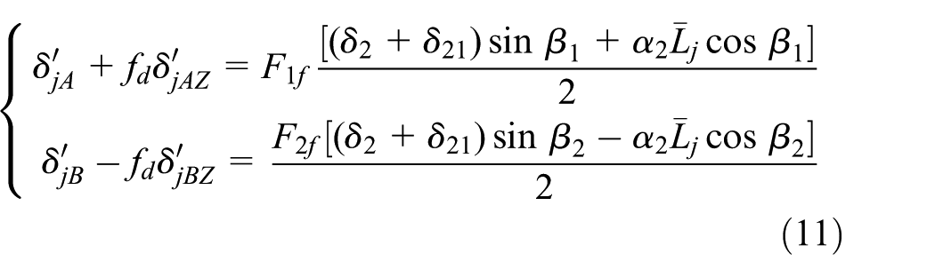
Equation (8) is substituted into equation (11). In this case, the left-hand side of equation (11) is the total deformation of the MPs. According to the nonlinear relationship between force and deformation, equation (11) is substituted into equation (9). The number of unknowns in equation (9) is equal to the number of equations, and so, those nonlinear equations can be solved using the fsolve 19 command in MATLAB to obtain α2 and δ21.
Elastic angle of CSGES meshing pair
When the CSGES meshing pair is analyzed, the fixed plate is fixed in the axial direction, and APF NZ and resistance torque M0 are loaded on the planet plate. The mechanical model of the CSGES meshing pair is established, as shown in Figure 6. The normal forces of the MPs are NnhA, NnhB, NnhC, and NnhD, and φnh represents the angle turned around in the mechanism.

Engagement-pair dynamic model. (a) Mechanical model of equal-speed meshing pair and (b) meshing of ball and slide groove.
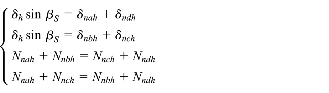
When the resistance torque M0 is not loaded, APF NZ is offered by the CMM. The rigidity coefficients of all points of the meshing pair are the same, which is represented as kh. The relative axial translational amounts that plane translational plate relative to fixed plate and planet plate are the same, represented by δh; relative to the fixed plate, the amount of axial translational of the planet plate is 2δh. The predeformation amounts generated at the MPs are δnah, δnbh, δnch, and δndh. Based on the static balance conditions of the planet plate, the following equation is derived

here, βS is the angle between the normal line of the MP and the plate plane, and ZS represents the number of steel balls in the cross-slide groove.
From the constitutive equation, the following equations are derived
Combining the above equations with equation (12), the equations are obtained as follows

In the process of force analysis, the fixed plate, the plane translational plate, and the steel balls between them are taken as one part, and the planet plate, the plane translational plate, and the steel balls between them are taken as another part. Under the condition of loading APF NZ, the resistance torque M0 is loaded on the planet plate. Based on the static balance conditions between the fixed or plane plate and the steel balls, the following equations can be derived
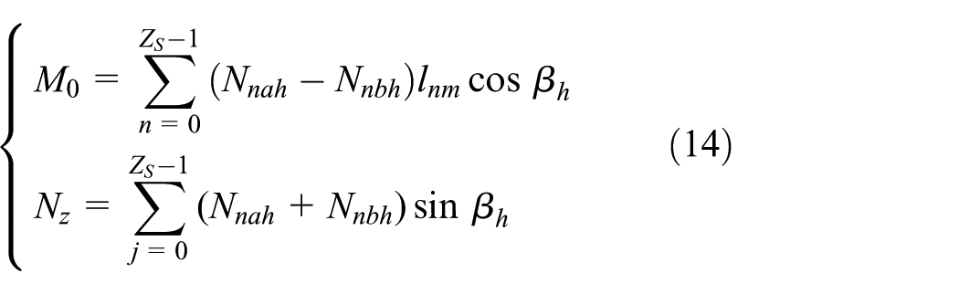
Here, when the planet plate is analyzed, we have m = 1 and ln1 = Rh|cos(2nπ/Zh)| + ecosφnh; when the fixed plate is analyzed, we have m = 2 and ln2 = Rh|cos(2nπ/Zh)| + esinφnh. The term RS represents the radius of the circle to which a steel ball belongs.
From the constitutive equation, the following equations are derived

here, δnaH, δnbH, δncH, and δndH represent the amount of torque deformation of each MP after loading resistance torque M0. The overall deformation amounts are expressed as δnAh, δnBh, δnCh, and δnDh. The term δH1 represents the amount of relative shift between the planet plate and the plane translational plate after loading resistance torque M0. The term δH2 represents the amount of relative shift between the fixed plate and the plane translational plate after loading resistance torque M0.
The amount of deformation of the MPs is non-zero, and the following equation is established

From the above equation, the following equation is derived for the amount of MP deformation

Equation (13) is substituted into equation (16). In this case, the left-hand side of equation (16) is the total deformation of the MPs. According to the nonlinear relationship between force and deformation, equation (16) is substituted into equation (14). The number of unknowns in equation (14) is equal to the number of equations, and so, those nonlinear equations can be solved using the fsolve 19 command in MATLAB to obtain α1h and α2h. The overall elastic angle of the CSGES meshing pair is α3 = α1h + α2h.
Analysis of elastic angle
In the process of analysis, if there is no particular indication, the parameters should be selected as follows: M0 = 5 N m, NZ = 600 N, K = 0.5, r0 = 4 mm, Zd = 14, ZS = 16, Z2 = 20, β* = 1.08, β1 = π/4, β = π/4, βS = π/4, rd = 1.5 mm, rs = 1.5 mm, rq = 1.5 mm, RS = 40 mm, and Rw = 40 mm. The number of steel balls of deceleration meshing pair and equal-speed meshing pair is a discrete variable, hence so is the elastic angle. Curve fitting is conducted on the experimental results to show the manner in which the elastic pattern changes.
Minimum APF for constant transmission
With the increase in rotation angle Φ1, the manner of variation in the minimum APF which is loaded to realize the constant transmission for deceleration meshing pair is shown in Figure 7(a). The APF changes periodically as the rotation angle increases: the period is 2π/Z2 (Z2 = 20) and the maximum value is 290.2 N, which is defined as the maximum value of the minimum APF of the deceleration meshing pair.

Minimum APF of equal-speed meshing pair. (a) Minimum APF of deceleration meshing pair, (b) minimum APF of RGES meshing pair, and (c) minimum APF of CSGES meshing pair.
With the increase in rotation angle Φ1, the manner of variation in the minimum APF which is loaded to realize the constant transmission for RGES meshing pair is shown in Figure 7(b). The APF changes periodically as the rotation angle increases: the period is 2Z2π/[Zd (Z2 + 1)] and the maximum value is 320.9 N, which is defined as the maximum value of the minimum APF of the RGES meshing pair.
With the increase in rotation angle Φ1, the manner of variation in the minimum APF which is loaded to realize the constant transmission for the CSGES meshing pair is shown in Figure 7(c). The APF changes periodically as the rotation angle increases: the period is 2Z2π/[ZS (Z2 + 1)] and the maximum value is 303.8 N, which is defined as the maximum value of the minimum APF of the CSGES meshing pair.
With the minimum APF loaded, the manner in which the amounts of MP deformation of the deceleration and RGES meshing pairs vary with rotation angle is shown in Figure 8(a) and (b), respectively. In one period, the amount of deformation at each FTMP is greater than zero and that at each NFTMP is zero, and the maximum amount of deformation appears in the first half period.

Meshing point (MP) deformation amounts. (a) Deceleration meshing pair, (b) ring-groove equal-speed meshing pair, (c) fifth steel ball of CSGES meshing pair, and (d) all steel balls of CSGES meshing pair.
With the minimum APF loaded, when the fixed plate and the plane translational plate mesh with the fifth steel ball in the CSGES meshing pair, the amount of MP deformation is shown in Figure 8(c). In one period, the amount of deformation at each FTMP is greater than zero and that at each NFTMP is zero. For Φ1 = 0, the amount of deformation at each MP in this meshing pair is shown in Figure 8(d). The amount of deformation at each FTMP is greater than zero and that at each NFTMP is zero.
When the minimum APF is loaded on the meshing pair, each FTMP deformation amount is greater than zero, the steel balls make real-time contact with the grooves, and each meshing pair realizes continuous transmission. When an APF is loaded practically, it has a fixed value. Therefore, the maximum value of the meshing pair minimum APF must be loaded to ensure continuous transmission of the meshing pair. Under those parameter values, a necessary and sufficient condition on the CBPT is that the maximum value of the minimum APF of the equal-speed meshing pair be loaded on the CBPT. With any change to the parameter values, the maximum values of the minimum APF of both the deceleration and equal-speed meshing pairs will change. Therefore, a necessary and sufficient condition on a CBPT constant transmission is that the larger of the maximum values of the minimum APF of both the deceleration and equal-speed meshing pairs be loaded on the CBPT.
Analysis of elastic angle for equal-speed meshing pair
The maximum value and amplitude change of the elastic angle of the equal-speed meshing pair are shown in Figure 9(a) and (b), respectively. The discrete points were obtained by calculation, whereupon curve fitting was conducted.

Elastic angle of equal-speed meshing pair: (a) maximum elastic angle and (b) amplitude change.
With the increase in the number of equal-speed steel balls, the maximum values of the elastic angles of the RGES mechanism (α2 max) and the CSGES mechanism (α3 max) decrease gradually. Within the unit interval, the decrease in amplitude becomes small gradually with the number of equal-speed steel balls. A nonlinear relationship is revealed between elastic angle and the number of equal-speed steel balls.
With increase in the number of equal-speed steel balls, the difference between α2 max and α3 max decreases. Within the unit interval, the decrease in amplitude becomes small gradually with the number of equal-speed steel balls. The ratio between α2 max and α3 max is a fixed value, which is about 0.6443 for this group of parameters.
With increase in the number of equal-speed steel balls, the elastic angle amplitudes of the RGES mechanism (Δα2) and the CSGES mechanism (Δα3) decrease gradually. Within the unit interval, the decrease in amplitude becomes small gradually with the number of equal-speed steel balls, as does the difference between Δα2 and Δα3. The ratio between Δα2 and Δα3 is a fixed value, with Δα2 > Δα3. Because the values of Δα2 and Δα3 are relatively small, the effect of Δα2 on α2 can be ignored, as can the effect of Δα3 on α3. Therefore, α2 max and α3 max can be replaced by α2 and α3, respectively.
The amounts of MP deformation of the ring-groove and CSGES mechanisms are shown in Figure 10(a) and (b), respectively. The deformation amount of FTMPs and NFTMPs decreases as the number of steel balls increases, and a nonlinear relationship is found between the deformation amount and the number of steel balls. The distance between the MP normal plane and the gyration center is a fixed, and the elastic angle is related to only the amount of MP deformation. Therefore, a nonlinear relationship is found between the amount of MP deformation and the number of steel balls, which also gives a nonlinear relationship between elastic angle and the number of steel balls.

MP deformation amount of RGES mechanism and CSGES mechanism. (a) MP deformation amount of RGES mechanism and (b) MP deformation amount of CSGES mechanism.
The elastic angle of the CSGES mechanism is composed of two parts: (1) the elastic angle generated by the fixed plate and the plane translational plate and (2) the elastic angle generated by the planet plate and plane translational plate. The elastic angle of the RGES mechanism is that caused by the fixed plate and the planet plate. Therefore, under the fixed parameter, α2 max is greater than α3 max. The elastic angle directly influences the transmission precision of the mechanism, so the RGES mechanism possesses a higher transmission precision. The rigidity coefficient of the inside MPs (k2) of the RGES mechanism is smaller than that of the outside MPs (k1). The rigidity coefficients of the two sides of the MPs of the CSGES mechanism are the same. During transmission, the MPs are switched between the FTMPs and the NFTMPs. As a result, the ratio between α2 max and α3 max is a fixed value; the amplitude of the elastic angle of RGES mechanism (Δα2) is much greater than that of CSGES mechanism.
Analysis of deceleration elastic angle
The elastic angle α1 max of the deceleration meshing pair is shown in Figure 11. As the number of deceleration steel balls increases, α1 max decreases. Within the unit interval, the decrease in amplitude becomes small gradually with Z2. A nonlinear relationship is found between elastic angle and the number of deceleration steel balls.

Elastic angle of deceleration meshing pair: (a) maximum elastic angle and (b) amplitude change.
As the number of deceleration steel balls increases, Δα1 decreases. Within the unit interval, the decrease in amplitude becomes small gradually with Z2 and eventually Δα1 is negligible. Therefore, when α1 is studied, the effect of Δα1 on α1 can be ignored, so α1 can be replaced by α1 max.
The amount of MP deformation of the deceleration meshing pair is shown in Figure 12. As the number of steel balls increases, the amount of FTMP deformation decreases in a nonlinear relationship, whereas there is no such exact relationship for the amount of NFTMP deformation. The elastic angle is generated by the amount of FTMP deformation.
MPs deformation amount.
As the number of steel balls increases, the distance between the MPs and the normal plane increases, and the number of steel balls and the distance are nonlinear relationships. Therefore, there is a nonlinear relationship between the amount of NFTMP deformation and the number of deceleration steel balls, thereby also making a nonlinear relationship between elastic angle and the number of deceleration steel balls.
Analysis of global elastic angle
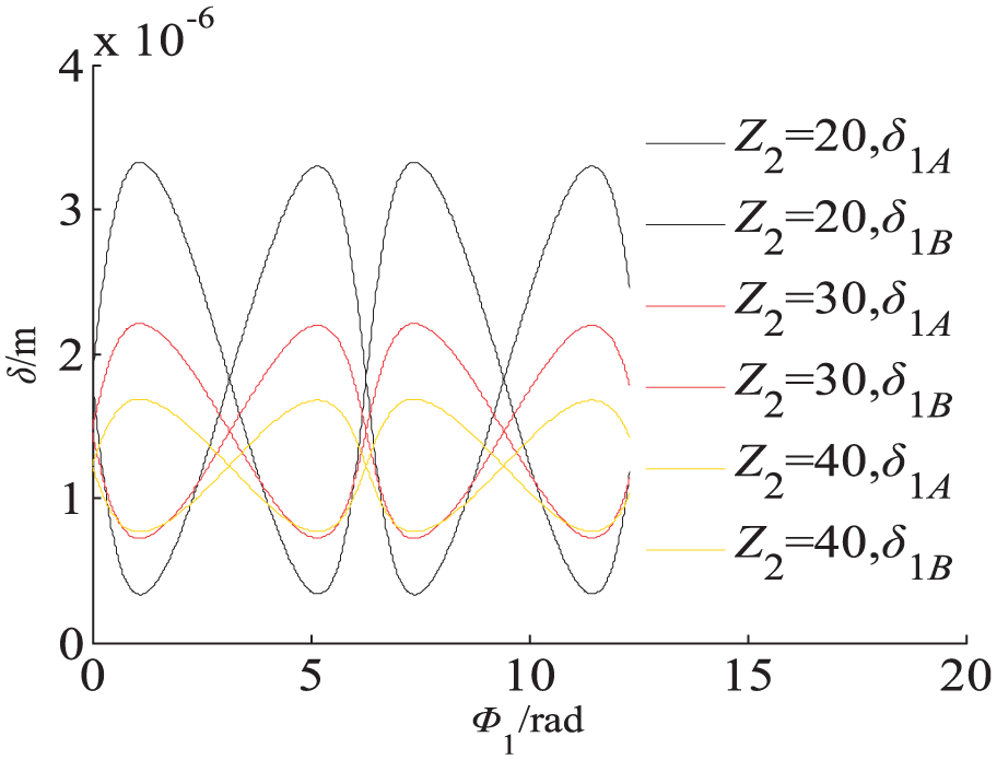
The elastic angle of a CBPT equipped with an RGES mechanism is αd, where αd = α1 + α2. The elastic angle of a CBPT equipped with a CSGES mechanism is αs, where αs = α1 + α3. The variations of αd and αs with Φ1 are shown in Figure 13(a) and (b), respectively. As can be seen from Figures 11(b) and 9(b), both Δα2 and Δα3 are smaller than Δα1 by three orders of magnitude, so the effects of Δα2 and Δα3 can be neglected. We consider the amplitude change range and the periods of αd and αs to be the same as those of α1, namely an amplitude change of about 2 × 10⁻⁴″ and a period T = 2π/Z2 (Z2 = 20).

Elastic angle of CBPT. (a) Elastic angle of CBPT equipped with RGES mechanism and (b) elastic angle of CBPT equipped with CSGES mechanism.
Analysis of parametric influence
Because the RGES mechanism has the higher precision, parametric analysis is conducted on the elastic angle αd of a CBPT equipped with an RGES mechanism. In the analysis process, αd is replaced by the maximum value of the elastic angle, namely, αdmax. There is a linear relationship between the mechanism transmission ratio and the number of deceleration steel balls. When the output and input shafts rotate in the same direction, the transmission ratio is (Z2 + 1)/2; when the output and input shafts rotate in the opposite direction, the transmission ratio is −(Z2 − 1)/2. Therefore, with the change in the number of steel balls, the influence of different system parameters on elastic angle is analyzed. Suppose that in the mechanical model of the meshing pair, the difference in the component forces (in the plate plane) of two points A and B or C and D on the steel balls is ΔF.
Influence of short-amplitude coefficient
The influence of the short-amplitude parameter on elastic angle is shown in Figure 14. With the increase in K, the elastic angle αdmax of the CBPT gradually decreases. Within the unit interval, the decrease in amplitude becomes small gradually with K; with the increase in Z2, αdmax gradually decreases, and the decrease in amplitude becomes smaller. Two groups of steel balls were selected arbitrarily and are designated xK1 and xK2 (xK1 > xK2). Their elastic angles are represented as αdmax (xK1, K) and αdmax (xK2, K), respectively, and the difference between them is denoted ΔαK = αdmax(xK2, K)−αdmax(xK1, K). When the number of deceleration steel balls is fixed, ΔαK decreases with K, and the decrease in amplitude becomes smaller. When the difference between xK1 and xK2 is fixed, ΔαK decreases with xK1 (xK2), and the decrease in amplitude becomes smaller.

Influence of K.
The planet plate and center plate are connected by the deceleration steel balls, which can be regarded as a parallel mechanism; Z2 represents the number of parallel mechanisms. With the increase in Z2, the number of parallel mechanisms increases, as does the bearing capacity of the CBPT. Derived from equation (1), the relationship between the amount of MP deformation and normal force is nonlinear, and the nonlinear coefficient is greater than unity. The short coefficient mainly affects the radius of curvature of the cycloid, so the larger the value of K, the greater the stiffness coefficient of the MP and the smaller the value of αdmax under the load condition. Therefore, with the increase in Z2 and K, αdmax gradually decreases; within the unit interval, the decrease in amplitude gradually decreases with Z2 and K.
The relationship between input-shaft eccentricity and K is linear and positively correlated, and as K increases, so does the dynamic imbalance of the system. Therefore, when designing the reducer, under the prerequisite of stable vibrations of the system, a larger value of K should be selected to improve the transmission precision of the system.
Influence of APF
The influence of APF NZ on elastic angle is shown in Figure 15. With the increase in NZ, αdmax decreases gradually; within the unit interval, the decrease in amplitude decreases gradually with NZ. With the increase in Z2, αdmax decreases gradually, as does the decrease in amplitude. Two groups of steel balls were selected arbitrarily and are designated xN1 and xN2 (xN1 > xN2). Their elastic angles are αdmax (xN1, NZ) and αdmax (xN2, NZ), respectively, and the difference between them is designated ΔαN = αdmax (xN2, NZ)−αdmax (xN1, NZ). When the number of deceleration steel balls is fixed, ΔαN does not change with NZ. When the difference between xN1 and xN2 is fixed, ΔαN decreases with xN1 (xN2), and the decrease in amplitude becomes smaller.

Influence of NZ.
The relationship between force and amount of deformation is nonlinear. The amount of MP predeformation increases with APF NZ, whereas the amount of torque deformation required to get the fixed ΔF decreases. Therefore, under the same resistance torque, αdmax decreases with APF NZ.
Sliding friction and rolling friction take place between the steel balls and the grooves. Therefore, the amount of wear of the meshing pair increases with the APF. This shortens the service life of the mechanism, increases the heat produced at MPs, and lowers the transmission efficiency of the system. Therefore, when designing a CBPT, once the conditions for transmission efficiency and service life have been satisfied, a large NZ should be selected to improve the transmission precision of the system.
Influence of radius of rolling circle
The influence of the radius r0 of the rolling circle on elastic angle is shown in Figure 16. With the increase in r0, αdmax decreases gradually; within the unit interval, the decrease in amplitude decreases gradually with r0. With the increase in Z2, αdmax decreases gradually, as does the decrease in amplitude. Two groups of steel balls are selected arbitrarily and are designated xr1 and xr2 (xr1 > xr2). Their elastic angles are designated αdmax(xr1, r0) and αdmax (xr2, r0), respectively, and the difference between them is designated Δαr = αdmax(xr2, r0) − αdmax(xr1, r0). When the number of deceleration steel balls is fixed, Δαr decreases gradually with r0, as does the decrease in amplitude. When the difference between xr1 and xr2 is fixed, Δαr decreases gradually with xr1 (xr2), as does the decrease in amplitude.

Influence of r0.
The relationship between r0 and e is linear and positively correlated (e = Kr0), so the greater the value of r0, the greater the turning radius li (li = |Z3esinθi|). The greater the turning radius, the smaller the elastic angle required to generate the same normal force from equations (1) and (2). Therefore, under the condition of a certain load, the bigger r0, the smaller αdmax.
The relationship between input-shaft eccentricity and r0 is linear and positively correlated. Therefore, the dynamic imbalance of the system increases with r0, and the vibration stability of the system decreases. Therefore, when designing the CBPT, once the conditions for vibration stability of the system have been satisfied, a larger r0 should be selected to improve the transmission precision of the system.
Influence
The influence of β on elastic angle is shown in Figure 17. With the increase in β, αdmax increases gradually; within the unit interval, the increase in amplitude becomes large with β. With the increase in β, when Z2 increases, the amplitude of αdmax decreases gradually. Two groups of steel balls were selected arbitrarily and are designated xβ1 and xβ2 (xβ1 > xβ2). Their elastic angles are designated αdmax(xβ1, β) and αdmax(xβ2, β), respectively, and the difference between them is designated Δαβ = αdmax(xβ2, β)−αdmax(xβ1, β). When the number of deceleration steel balls is fixed, Δαβ increases gradually with β, as does the increase in amplitude. When the difference between xβ1 and xβ2 is fixed, Δαβ decreases gradually with xβ1 (xβ2), as does the decrease in amplitude.
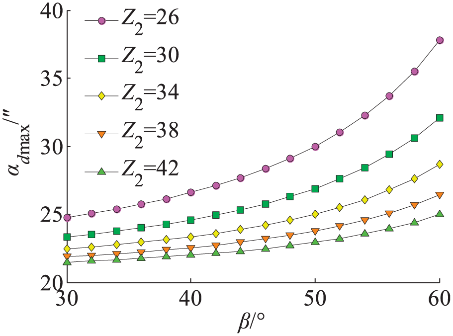
Influence of β.
The value of β mainly influences the normal force direction of the MPs. From equations (3) and (4), when NZ is fixed, the amount of MP predeformation decreases with β, the component forces (in the plate plane) decrease, and the deceleration MP increases as the meshing pair reaches equilibrium under the condition of the fixed resistance torque. Therefore, for all other parameters fixed, the greater β, the greater αdmax.
With the increase in β, after wearing of the meshing pair, the contact area between the steel balls and the groove increases, as does the axial displacement of each plate to eliminate wearing clearance. This increased contact area reduces the transmission efficiency of the mechanism and increases the degree of wear per unit time; when the axial-direction output quantity of the CMM is fixed, the service life of the mechanism will be reduced. Therefore, when designing the reducer, once the conditions for transmission efficiency and service life have been satisfied, a smaller β should be selected to improve the transmission precision of the system and increase its service life.
Influence of resistance torque
The influence of M0 on elastic angle is shown in Figure 18. With the increase in M0, αdmax increases gradually; within the unit interval, the increase in amplitude becomes large with M0. When M0 is fixed, with increase in Z2, αdmax decreases gradually, as does the decrease in amplitude. Two groups of steel balls were selected arbitrarily and are designated xM1 and xM2 (xM1 > xM2). Their elastic angles are designated αdmax(xM1, M0) and αdmax(xM2, M0), respectively, and the difference between them is designated ΔαM = αdmax(xM2, M0)−αdmax(xM1, M0). When the number of deceleration steel balls is fixed, ΔαM increases gradually with M0, as does the increase in amplitude. When the difference between xM1 and xM2 is fixed, ΔαM decreases gradually with xM1 (xM2), as does the decrease in amplitude.

Influence of M0.
The value of M0 mainly influences the normal force of the MPs. From equations (4), (5), (9), and (10), when NZ is fixed, with increase in M0, the FTMP component forces (in the plate plane) increase gradually, whereas the NFTMP component forces decrease gradually. Therefore, for all other parameters fixed, the larger M0, the larger αdmax.
When the system parameters are fixed, with the increase in M0, the difference of the normal forces between the FTMPs and NFTMPs increases. When M0 reaches a certain value, gear backlash will arise at the NFTMPs and will influence the operational stability of the mechanism. When a large resistance torque is loaded on the transmission mechanism, the APF can be increased to improve the operational stability of the mechanism.
Experiment
In the experiment, an eddy-current sensor is used to collect the component displacement. Its actual sensitivity is 7.99 V/mm, its nonlinearity is 0.84%, and its sensitivity deviation is 0.12%. A 24-digit high-precision collection card is used to collect the data. Its simulated input channel is eight-channel single-ended current input, the resolution is 12 bit (4096), and the sample rate of each channel is 20 kHz.
Experimental principle
The input shaft of a CBPT is coupled with a fixing device, and the output shaft is coupled with the hollow shaft of a magnetic powder brake. A coupling disk is installed on the shell of the magnetic powder brake and is coupled with the retarder output shaft by a key. A cuboid-shaped test bar is coupled with the output shaft by a locking bolt. The test end plane is parallel to the plane of the test bar in the eddy-current sensor, the clearance between them is 1 mm, and the radial distance between the geometric center of the test end and the output shaft is h = 0.1 m.
Suppose that the output load of the magnetic powder brake is fixed. A stepper motor drives the retarder to rotate at low speed. By means of the coupling disk, the retarder output shaft rotates the shell of the magnetic powder brake. The output load of the magnetic powder brake is applied to the CBPT output shaft, thereby generating an elastic angle; the prototype output shaft followed by the test bar has the same angle. The clearance changes between the test end of the eddy-current sensor and the test bar, which we designate Δh (unit: m). The eddy-current sensor measures this clearance value, which is then used to calculate the elastic angle of the CBPT. In the test process, the rotation angle of the test bar is very small, so it is assumed that the test bar and the test end of the eddy-current sensor are invariably parallel, whereupon an approximate calculation is conducted. Setting the test value as αt (unit: ″), the following equation can be derived (Figure 19)


Experimental test device.
Experimental test and analysis
The selected parameter values are K = 0.6, Zd = 10, r0 = 0.8 mm, Z2 = 26, rd = 2 mm, rq = 2.5 mm, Rw = 25 mm, and a CBPT diameter of 65 mm. When the output torque of the magnetic powder brake is zero, the retarder rotates bilaterally and the rotation angle of test bar is 4.58″, which is generated mainly by the bearings on the input shafts. In the test process, the stepper motor rotates unilaterally, and the output torque of the magnetic powder brake is increased gradually from zero to 5 N·m increments of 0.5 N m; after each increase, a set of data is collected. For APFs of 600, 500, and 400 N, the experimental results are shown in Figure 20(a)–(c), respectively. Suppose that the theoretically calculated value is αc and that the difference between αc and αt is Δαdmax. For the APFs of 600, 500, and 400 N, the variation of Δαdmax is shown in Figure 20(d).

Result comparison. (a) 600 N, (b) 500 N, (c) 400 N, and (d) Δαdmax.
As shown in Figure 20, within the unit interval, αc and αt increase with M0; as the APF is increased, the nonlinear relationships between αc and M0 and between αt and M0 gradually weaken. For an APF of 600 N with M0 = [0,4.5), Δαdmax ≥ 0 and has its maximum value of 32.3″ at M0 = 3 N·m; with M0 = [4.5,5.0), Δαdmax < 0 and decreases gradually with M0. For an APF of 500 N with M0 = [0,4.0), Δαdmax ≥ 0 and has its maximum value of 25.8″ at M0 = 2.5 N·m; with M0 = [4.0,5.0), Δαdmax < 0 and decreases gradually with M0. For an APF of 400 N with M0 = [0,2.5), Δαdmax > 0 and has its maximum value of 16.8″ at M0 = 1.5 N·m; with M0 = [2.5,5.0), Δαdmax < 0 and gradually decreases and then quickly increases with M0, attaining its minimum value of −49.8″ at M0 = 4 N·m and its maximum value of 39″ at M0 = 5 N·m.
The error between αc and αt is due to the eccentric section bearing of the output shaft. Regardless of this error, the results of the experimental test in terms of size and variation trend are better consistent with those of the theoretical calculations. The experimental test validates the theoretical calculation of the CBPT elastic angle.
Conclusion
The results of this study reveal that a necessary and sufficient condition for the CBPT is the APF, which is the larger of (1) the maximum value of the minimum APF of the deceleration meshing pair and (2) the maximum value of the minimum APF of the equal-speed meshing pair. For the same parameter values, the transmission precision of the RGES mechanism is higher than that of the CSGES mechanism. When the rotation angle Φ1 changes, the ranges of the elastic angles of the deceleration and equal-speed meshing pairs are very small. Hence, any variation in elastic angle can be neglected, and the elastic angle can be regarded instead as a fixed value. As the number of steel balls increases, α2 max and α3 max decrease gradually, the difference between them becomes smaller, and the ratio between α2 max and α3max tends to a fixed value that is less than unity. The relationships between parameters K, NZ, r0, and β with αdmax are nonlinear ones. Δαdmax decreases gradually with K, NZ, and r0, but increases gradually with β. When the number of deceleration steel balls is fixed, the differences ΔαK and Δαr decrease with both K and r0, whereas the difference ΔαN does not vary with NZ, and the difference Δαβ increases gradually with β. When the difference between two groups of steel balls is fixed, ΔαK, ΔαN, Δαr, and Δαβ decrease with the number of steel balls. When the selected values of K, NZ, and r0 are big and that of β is small, the CBPT can acquire higher transmission precision. Under the condition of the fixed parameters, the larger the transmission ratio is, the higher the transmission precision of the mechanism becomes. The results of an experimental test of the CBPT elastic angle are consistent with those calculated theoretically, which validates the theoretical calculations.
Footnotes
Handling Editor: Hiroshi Noguchi
Declaration of conflicting interests
The author(s) declared no potential conflicts of interest with respect to the research, authorship, and/or publication of this article.
Funding
The author(s) disclosed receipt of the following financial support for the research, authorship, and/or publication of this article: This study was supported by the National Natural Science Foundation of China (no. 51275440).