
Abstract
Backlash is the inherent characteristic of gear transmission system. It is an important mean to measure and compensate backlash to improve transmission performance. When the driving gear reverses, due to the existence of backlash, the driven gear will still keep its original steering due to inertial motion until the driven gear collision with the driving gear. In this paper, based on the analysis of the tooth gap of the driving gear and the driven gear, an on-line measurement method of the meshing tooth gap combining the angular velocity of the load end with the information of the Angle position of the two axes of the master-slave gear is presented. This method uses the gyroscope at the load end (driven wheel) to monitor the sudden change of angular velocity at the moment of gear reverse impact and re contact, and the signal is used as the judgment basis for the reverse contact moment of the driving gear and driven gear. Then, the angular position data of driving gear and driven gear are fused at the time of reverse rotation and contact impact, and the backlash of the gear is calculated online. Finally, setting up an experimental platform for measuring backlash, and the proposed method is verified. The experimental results show that the proposed method can achieve accurate backlash measurement.
Introduction
Compared with direct drive, gear drive has the characteristics of low power consumption, small volume and light weight, which is widely used in electromechanical system. 1 Its advantages are particularly obvious in the electromechanical system, which has the characteristics of light weight, heavy load, low power consumption. 2 As mechanical transmission, torque change and deceleration control equipment, gear is widely used in industry and aerospace. 3 On the inertial stabilization platform of aerial remote sensing, due to the influence of flight platform environment, it requires small volume, light weight and strong anti-interference characteristics. The system design usually adopts one or multi-stage gear transmission to achieve compact and strong torque drive. 4 There should be a backlash between the gears to lubricate the gears to prevent the gears from jamming. And the wear and tear of long-time operation will cause the asymmetric clearance of the gear, 5 or due to mechanical wear, structural deformation, loose assembly and other phenomena, the size of transmission backlash will change slowly with time. 6 Therefore, backlash is an indispensable part of the indirect transmission system, and also an important factor affecting the transmission performance of the system. If not handled properly, the stability accuracy of the system will be reduced, and even the system will oscillate. 7 If no effective means can be taken to eliminate or reduce the nonlinear influence of the gear gap, the dynamic and static performance of the system will be greatly reduced, and in serious cases, the system will even become unstable and cannot be adjusted. 8 In order to control the gear transmission system error caused by backlash, relevant scholars have done a lot of work in backlash measurement, modeling and error compensation.8,9
One idea is from the point of view of the physical elimination of backlash, using the method of multi machine linkage can reduce backlash, greatly reduce the non-linear backlash error, and improve the transmission accuracy. There is a way to reduce the backlash by improving the machining accuracy and assembly accuracy of gears, 10 however, this method increases the volume and power consumption of the system, and the cost is high, its application is limited. At the same time, too small backlash will lead to excessive damping of transmission link or the phenomenon of jamming. Therefore, another idea is to maintain a certain backlash, through the measurement and modeling of backlash, supplemented by corresponding control methods, to suppress the impact of clearance on transmission accuracy and transmission performance. 11 The scheme reduces the requirements of gear processing and assembly process, has the advantages of low cost and quick effect, and is the future development direction. Backlash measurement is the key technology of the scheme. 12
The traditional methods of backlash measurement include lead wire method and gap measurement method, 13 The backlash can be obtained by measuring the thickness of the thinnest part after the gear extrudes the lead wire or by measuring the data with a feeler gauge. The traditional method can get better precision in static measurement, and can be used as a reference for single backlash measurement. In Lin et al., 14 a distributed control system based on Siemens drive motor is designed, and the rotation measurement method is designed for backlash measurement and adjustment. In Liu et al., 15 using a series of devices, a method is proposed to fix one gear first and then rotate the other gear. The clearance between two gears is measured by measuring the rotation of the rotating gear. In Wang, 16 a movable mechanism with some sensors was designed to calculate the backlash by measuring torque. Similar to the method in this paper, some researches also use the characteristic of the driving gear and the driven gear out of synchro inversion to study the backlash. In Zhang et al., 17 the inertia phenomenon of backlash described in this paper is established as a hysteresis backlash model. The low-frequency sinusoidal excitation with small amplitude is taken as the input of the system. The fundamental component is extracted from the output signal of the system by discrete Fourier transform, and then the relationship between the phase angle of the description function and the phase angle of the basic element is used to identify the backlash. Li 18 for measuring the gear reducer backlash, the encoder is also used to take the rotating unit and the load end as the input and output terminals respectively, and other sensors are used for auxiliary detection. The comparison unit is configured to compare and process the rotation speed and angular position information at both ends, and finally obtain the backlash.
These schemes can get good measurement results, but the system structure is more complex and more sensors need to be configured. When it is not possible to directly contact the gear for measurement, or it is necessary to measure the backlash when the transmission system is working, the above method cannot be implemented. The real-time on-line measurement proposed in this paper does not need any additional control system, it only needs encoder and gyroscope. When the transmission system is working, the data of encoder and gyroscope can be collected, and the backlash can be measured by using the formula. It is also possible to use this method for regular measurement.
In this paper, the primary transmission system composed of rigid short tooth gear is taken as the research object, and the influence of deformation and torque on the meshing clearance of gears is ignored, the driven gear is connected to the gyroscope as the load end. The relationship between the angular information of both sides of gears and the angular velocity of the load end in the transmission system is discussed, also the representation of the backlash in the moving state. On this basis, the paper studies the method of calculating the transmission backlash on-line by synthetically applying the angular velocity of the load end and the output information of the encoder fixed with the driving and driven shaft, and verifies the above method on the experimental platform.
Backlash description
In the process of gear meshing transmission, in order to form lubricating oil film between meshing tooth profiles and avoid sticking due to the heating and expansion of gear tooth friction, clearance must be reserved between tooth profiles. This reserved clearance is called meshing-teeth side clearance. The definition of meshing-teeth side clearance is: when a pair of gears are driven, the difference between the width of the slots on one pitch circle and the thickness of the teeth on the other pitch circle. When the radius of the gear is fixed, the meshing-teeth side clearance can correspond to a center angle of the graduation circle. The center angle corresponding to the meshing-teeth side clearance is called backlash. Backlash is a common technical parameter in transmission control system. If the backlash does not meet the use requirements, the transmission performance of the system will decline, which needs to be corrected and compensated. The backlash and related parameters between the driving and driven gears of the primary drive system are shown in Figure 1.
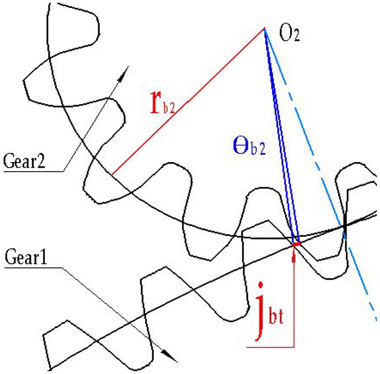
Geometric diagram of backlash between the driving and driven gear sets.
In Figure 1, gear 1 is the driving gear, gear 2 is the driven gear, circle O2 is the origin of the driven gear, jbt is the tooth side clearance, θb2 is the center angle (backlash) of the driven gear corresponding to the meshing-teeth side clearance, and rb2 is the radius of the driven gear. As the backlash is very small, the relationship between the meshing-teeth side clearance and backlash can be obtained according to the approximate geometric relationship of small angle as follows:
In formula (1), the θb2 unit is degree “°,” and the unit of jbt and rb2 are the same, which can be expressed in meter “m” or millimeter “mm.” As can be seen from this, for fixed gear pairs, the meshing-teeth side clearance and backlash are the description of the relative relationship between gears in terms of distance and angle, θb2 and jbt are one-to-one correspondence.
Backlash measurement method
Backlash static off-line measurement
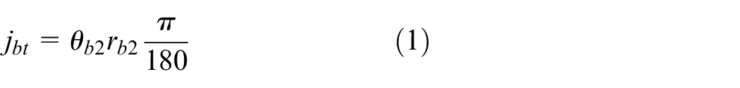
Feeler gauge is a tool to measure the meshing-teeth side clearance directly. The feeler gauge can directly measure it by inserting the different thickness combination of the feeler into the two gears, and then the backlash can be calculated by formula (1). The feeler gauge used in this paper is shown in Figure 2.
Graph of the feeler gauge.
The thickness of the plug in the feeler gauge is 0.05 mm, 0.06 mm, 0.07 mm, 0.08 mm, 0.10 mm, 0.15 mm, 0.20 mm, 0.25 mm, 0.30 mm, 0.40 mm, 0.50 mm, and 0.75 mm respectively. The meshing-teeth side clearance can be measured by combining different thickness plug into the backlash to be measured. Because of its high measurement accuracy, this paper chooses the backlash calculated by static measurement of backlash with feeler gauge as the evaluation standard of dynamic online measurement of backlash accuracy.
On line measurement of backlash
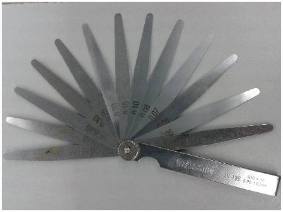
The gear pair shown in Figure 1 shows that when the driving gear makes reciprocating return movement, the movement of the driven gear has a lag time compared with that of the driving gear due to the existence of backlash. That is to say, when the driving gear reverses due to the motor control, the driving gear and the driven gear are out of contact on this tooth surface, and the driven gear continues to move in the original direction due to the inertia. Until the contact with the next tooth surface of the driving gear begins, the driven gear will catch up with the movement of the driving gear again. 19 In this process, the encoder can sense the reverse rotation, and the gyroscope at the load end can detect the angular velocity generated when the driving gear and the driven gear contact and collide again, and these two encoders can detect the time when the gear set enters into different states. Figure 3 shows the configuration of the system.
System structure configuration.
The reverse time of driving gear is set as t1, and the time when the driven gear recontacts the driving gear is set as t2. The backlash is the sum of the angles of the opposite movement between driving gear and driven gear in the time period t1∼t2. The angular position of driving gear at t1 time is set as θz1, the angular position of driving gear at t2 time is set as θz2, the angular position of load gear at t1 time is set as θc1, the angular position of load gear at t2 time is set as θc2, the gear teeth number of driving gear is Z1 and the gear teeth number of driven gear is Z2. Taking the driven gear as the reference gear, according to the corresponding relationship between the center angle of the driven gear and the driving gear, the backlash can be calculated online by the following formula:
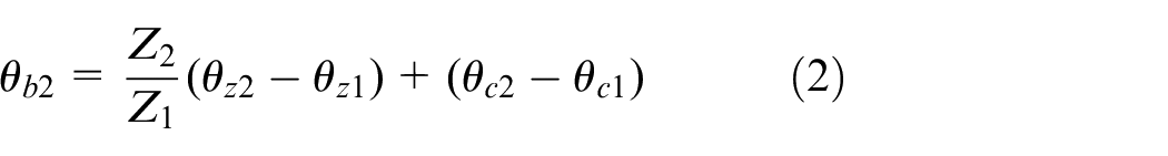
Wherein, θz1, θc1, θz2, and θc2 are read at the time t1 and t2 from encoder. It is known that the accuracy of backlash online detection is determined by the accuracy of the starting and ending time of return motion of gear set. In the online measurement, the contact time between the driving gear and the load gear should be distinguished as much as possible. The gyroscope fixed on the load platform at the driven gear end can solve this problem well.
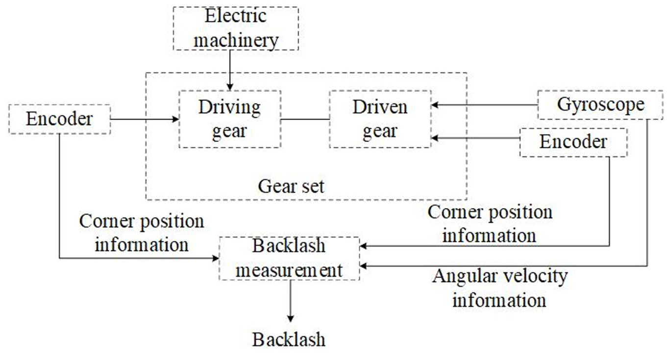
In the return motion, the driving gear and driven gear encoder readings θz1 and θc1 are read at the time t1 of the reverse motion of the driving gear. When the driving and driven gear are from the non-contact state to the contact state (i.e. time t2), the gyroscope of the load platform will instantaneously sense the angular velocity signal caused by the contact impact of the two gears. The time when the angular velocity surges due to gear contact and impact for the first time is t2. The encoder parameters θz2 and θc2 are read separately at t2 moment. The flow chart of on-line backlash detection method is shown in Figure 4.
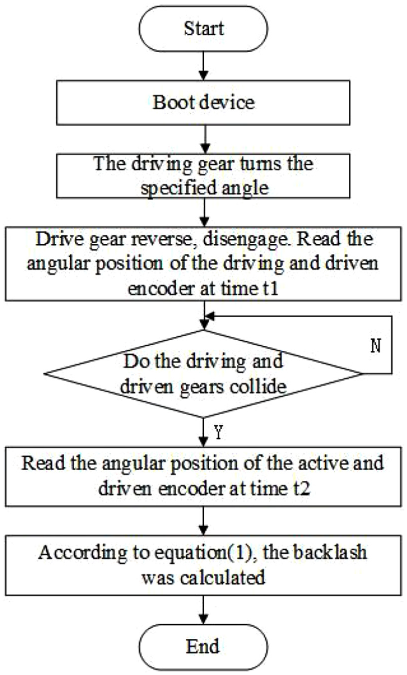
Flow chart of online backlash detection.
Experiment
Backlash test platform
In order to verify the research method, the present paper set up the experimental platform for backlash detection, and the raw data were obtained by the backlash detection experimental platform. The experimental platform was mainly composed of power supply, mechanical platform body, control system, driving/ driven gear pair, motor, driving gear encoder, driven gear encoder, inertial measurement unit (gyroscope) and conductive slip ring. The physical object was shown in Figure 5.
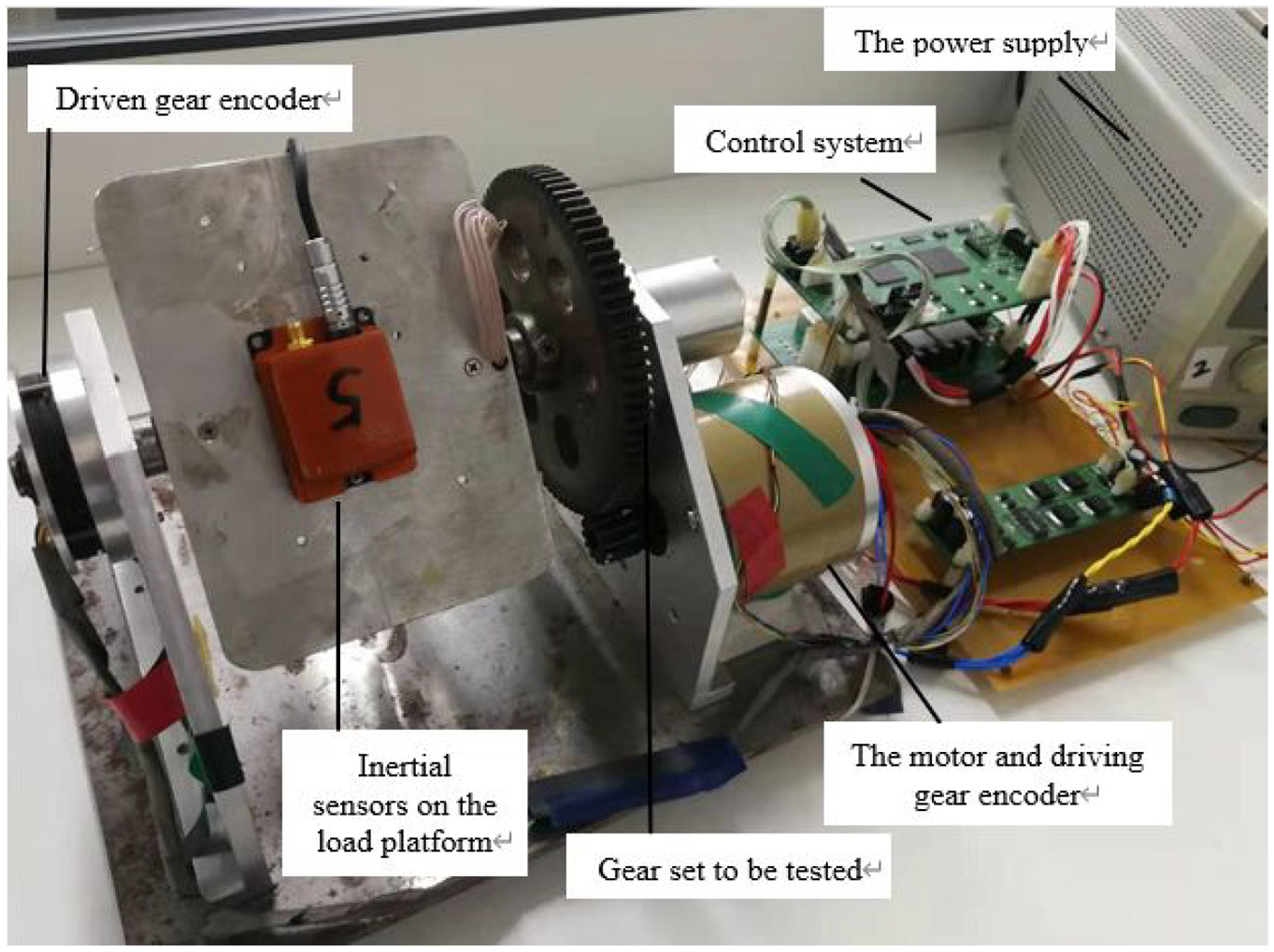
Physical picture of vibration load platform.
In Figure 5, the control system was used for controlling the motor to drive the driving gear to rotate forward and backward. The driving gear encoder and the driven gear encoder were used to measure the angular position of the driving gear and the driven gear. The gyroscope was used to get the angular velocity of the contact time between the driving gear and the driven gear. The conductive slip ring supplies power to the inertial measurement unit on the load and transmits angular velocity information to the control system. 20 The driving gear and driven gear were fixed to the pedestal and the motor shaft respectively. The position of the motor shaft could be adjusted by screw T, and the distance between the driving shaft and the driven shaft could be changed by adjusting the screw T, thus the backlash between the driving gear and the driven gear could be changed. Gear pair and backlash adjustment mechanism are shown in the Figure 6 below.
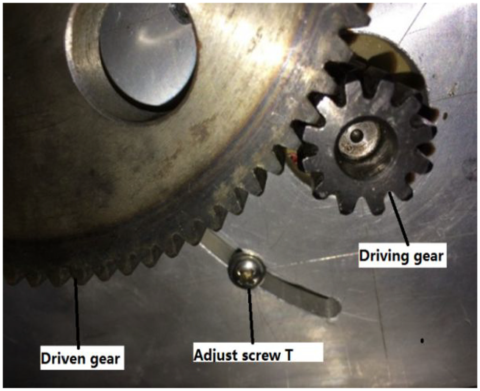
Gear gap adjusting device.
The following Table 1 shows the parameters of the gear used in the experiment:
Basic gear parameters in backlash measurement.
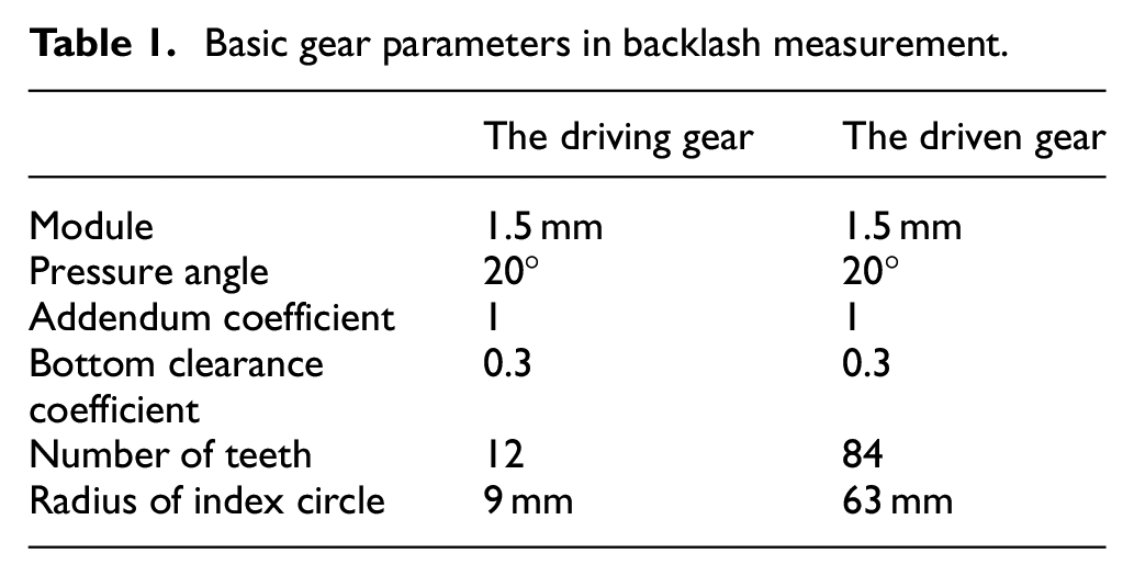
Inertial measurement unit adopted MTi-700 produced by X-sens Company in the Netherlands. For the MEMS gyroscope, the zero-bias stability was 10°/h, -3dB bandwidth was 415Hz, the measurement scope was 450°/s and the signal output frequency was 400 Hz. The angular position sensor selected DS-58 and DS-37 of Netzer Company in Israel. The DS-58 static error is less than 0.015°, and the DS-37 static error is less than 0.025°.
Test experiment of platform backlash
Experimental scheme
On the basis of theoretical analysis, this paper uses the gear gap test platform built above according to the method flow shown in Figure 4, the on-line detection method of transmission backlash based on angular velocity and position information fusion is verified by experiments.
The process of the experiment is as follows:
Adjust screw T to adjust the backlash between driving wheel and driven wheel, and complete the control system debugging and signal connection test.
Use feeler gauge to measure the backlash on the tooth side to be measured, calculate the backlash according to formula (1), and record.
In order to ensure the experimental measurement accuracy, it is necessary to carry out multiple positive and negative measurements. This experiment will control the driving motor in the control system to drive the load platform to do a long-time reciprocating swing and continuous measurement for many times. The unstable oscillation of the system will make the output error of the gyroscope. In order to make the gyroscope not affected by the error at the moment of reversal and accurately sense the angular velocity signal at that moment, it is necessary to ensure that the system is stable and vibration free before and after the reversal. In this paper, the swing amplitude of the gear is set as 90°, a positive and negative rotation is a cycle with a period of 35 s. This ensures that there is a certain time to keep the device stable before reversing. That is to say, the movement state of the load platform is as follows: the load gear rotates 90° forward → 90° reverses → 90° reverses, and circulates reciprocally. The data measurement is carried out when the reverse direction passes through the backlash.
When the control system outputs the command, the output angles E and a of the encoder a t the driving gear end at the reverse time t of the motor (driving gear) are read. Monitor the output signal of the gyroscope installed on the load platform. When the gyroscope senses the contact between the main gear and the slave gear, the output time of the angular speed is t. T read output angles a and a of encoder at driven gear end at any time.
System calculated backlash based on the formula (1).
The results of on-line measurement are compared with those of feeler gauge measurement.
Analysis of data
Use the adjusting screw T to adjust the gear backlash as shown in Figure 4. Before online measurement, use feeler gauge to measure tooth backlash. The meshing-teeth side clearance measured by feeler gauge is 0.25 mm, and the backlash calculated by formula (1) is 0.2274°. This value is taken as the reference value to provide the evaluation reference for the following dynamic measurement results of backlash.
Then, according to the on-line backlash detection method described above, the reciprocating rotation experiment of the gear set is carried out on the backlash vibration experimental platform. The backlash is calculated by processing the sensor output data, and the backlash measurement results are compared with the static bottom feeler gauge measurement results.
In the experiment, the triangle wave is used as the driving signal of the motor, and the angular position of the driven gear at the load end changes between 180° and 270° by the motor drive. The obtained angular position signals of driving gear and driven gear are shown in Figure 7 respectively.
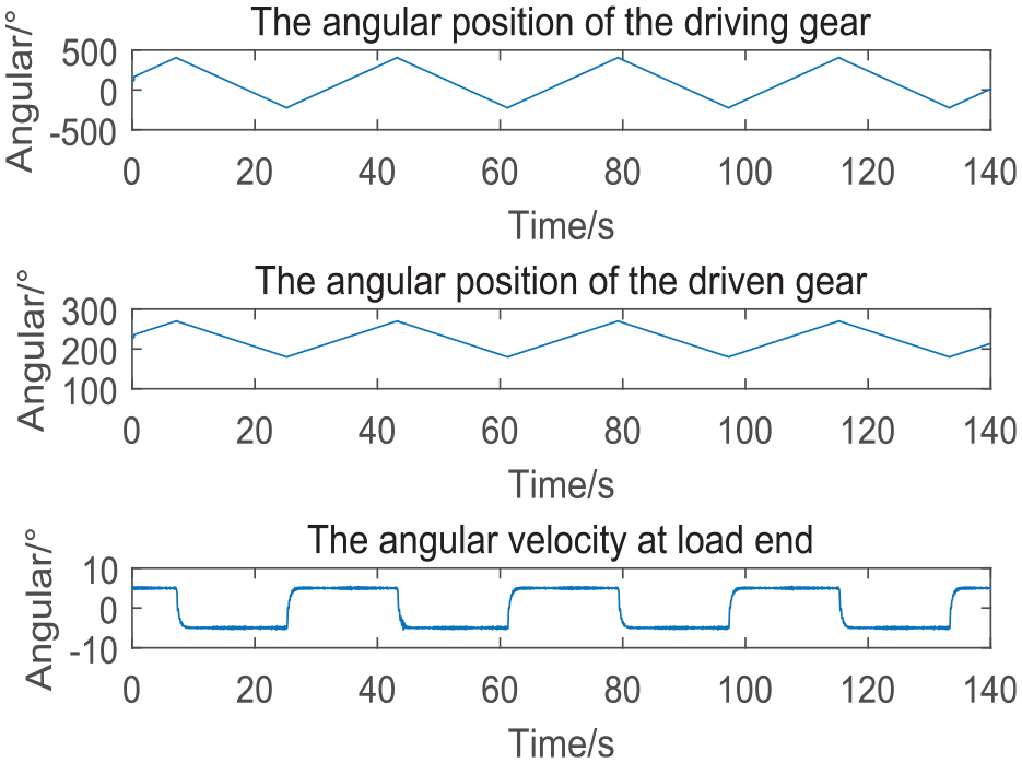
Angle position and load angular velocity of driven gear in rotary experiment.
It can be seen in Figure 7 that the driving gear drives the driven gear to do reciprocating angular motion. The waveforms of the change of the driving gear angle position and the driven gear angle position are all triangular waves, and the change rules of the driving gear angle position and the driven gear angle position from increase to decrease or from decrease to increase are consistent.21,22 According to the physical process described above, the driven gear is out of contact with the driving gear due to backlash after the driving gear moves in reverse direction. Due to the inertia, the driven gear still keeps its original direction for rotation until it contacts again and then rotates in reverse with the driving gear. Therefore, the angle position of driving wheel and driven wheel at the time of t1 and t2 detected in real time is made difference (θz1-θz2,θc1-θc2), and then brought into formula (2) to calculate the backlash accurately, and then compared with the reference value measured by feeler gauge for error analysis. According to the on-line backlash detection method proposed above, seven groups of experiments are repeated, and the data is shown in Table 2.
Measured angular position data and backlash calculation results in rotary process.
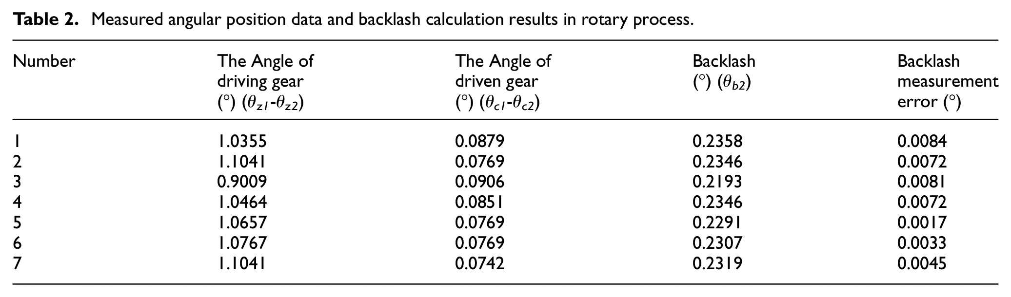
The backlash measurement error in Table 2 is the difference between the result calculated by the method in this paper and the result calculated by the feeler gauge. According to the data calculation results in the table, the mean error of the online measured backlash value is 0.0058° compared with the reference value of the true value, and the relative error is 2.6%. The maximum error is 0.0084°, the minimum value is 0.0017°, and the standard deviation of 7 measurement errors is 0.0024°. It can be seen from the statistical results of the error data that the online measurement accuracy of this method is high, and the fluctuation of each measurement result is very small. Compared with the two schemes mentioned in the introduction, which also make use of the inertia hysteresis phenomenon to measure the backlash, the measuring principle and equipment configuration in this paper are relatively simple and the accuracy is equal. This proves the feasibility of this method.
Conclusion
In this paper, based on the relative motion relationship between the driving gear and the driven gear, the backlash test platform and the reciprocating motion experiment are designed to verify the on-line detection method. The experimental results show that this method can calculate the backlash accurately, and the results of multiple measurements have good repeatability. However, the measurement method in this paper still has some limitations. This method only takes the spur gear as the research object, detects the contact impact time through gyroscope at the reciprocating moment, collects the data of encoder at this moment, analyzes and calculates the backlash. For other types of gear systems, this method and sensor configuration need to be optimized. The on-line backlash detection method proposed in this paper, using the mapping relationship between the load end angular velocity and the double end angular position of the driving gear and driven gear and the backlash in the transmission process, establishes the backlash expression, realizes the system level measurement of the backlash, and provides the basis and basis for the backlash error modeling compensation in the subsequent control links.
Footnotes
Author Contributions
Conceptualization, Ming Li and Yanshun Zhang; Methodology, Ming Li; Software, Chuang Peng and Dong Mu.; Validation, Ming Li, Yanshun Zhang and Chuang Peng.; resources, Dong Mu.; writing—original draft preparation, Ruirui Liang and Zhen Wan; writing—review and editing, Ming. Li.
1. Ming, Li.; Jie, Li. Modeling and simulation of unbalance disturbance for inertially stabilized platform. Journal of Chinese Inertial Technology
2. Ming, Li.; Jie, Li.; Yanshun, Zhang. Modeling and simulation of imbalance disturbance for inertially stabilized platform. Journal of vibration and shock
3. Ming, Li.; Jie, Li.; Yanshun, Zhang. Analysis of the effect of disturbance for remote sensing platform’s dynamical characteristic*. Proceedings of 2014 IEEE Chinese Guidance. Navigation and Control conference
4. Ming, Li.; Jie, Li.; Renqiang, Zhang. Unbalance Disturbance Restraining for Inertial Stabilized Platform. CCDC
5. Ming, Li.; Hang, Feng. Modeling and Simulation for Z-axis Force/Position-servo System of Assembly Manipulator. CCDC
6. Ming, Li.; Hang, Feng.; Yanshun, Zhang.RBF neural network tuning PID control based on UMAC. Journal of Beijing University of Aeronautics and Astronautics
1. Yanshun, Zhang.; Shuangji, Feng.; Zhanqing, Wang.; Xiaopeng, Xi.; Ming, Li. A Novel Separated Position and Orientation System Integrated with Inertially Stabilized Platform. Mathematical Problems in Engineering, 2018, 18(1): 1–10.
2. Yanshun, Zhang.; Baichao, Ding.; Xiaojuan, Huang.; Tao,Yang.; Xiaodong, Liu.Multi-Sensor, Adjustable-Period Integrated Navigation Method Based on Multi-Stage Signal Trigger for Underwater Vehicles, Journal of Navigation
3. Yanshun, Zhang.; Chuang, Peng.; Dong, Mou.; Ming, Li.; Wei, Quan. An Adaptive Filtering Approach Based on the Dynamic Variance Model for Reducing MEMS Gyroscope Random Error, Sensors
4. Yanshun, Zhang.; Yingyue, Li.; Chuang, Peng.; Ming, Li.; We, Wang.; Dong, Mou. The Height-Adaptive Parameterized Step Length Measurement Method and Experiment Based on Motion Parameters, Sensors
5. Yanshun, Zhang.; Xu,Yang.; Yunqiang, Xiong.; Xiangming, Xing.; Zhanqing, Wang. The Standing Calibration Method of MEMS Gyro Bias for Autonomous Pedestrian Navigation System, Journal of Navigation
6. Yanshun, Zhang.; Yunqiang, Xiong.; Yixin, Wang.; Chunyu, Li.; Zhanqing, Wang. An Adaptive Dual-Window Step Detection Method for a Waist-Worn Inertial Navigation System, Journal of Navigation
7. Yanshun, Zhang.; Yajing, Guo.; Tao, Yang.; Chunyu, Li.; Zhanqing, Wang. A novel separation and calibration method for DVL and compass error in dead reckoning navigation systems, Measurement Science & Technology
8. Yanshun, Zhang.; Tao, Yang.; Chunyu, Lia.; Shanshan, Liua.; Chaochao, Dua.; Ming, Li. Fuzzy-PIDcontrol for the position loop of aerialinertially stabilized platform. Aerospace Science and Technology
6.
Declaration of Conflicting Interests
The author(s) declared no potential conflicts of interest with respect to the research, authorship, and/or publication of this article.
Funding
The author(s) disclosed receipt of the following financial support for the research, authorship, and/or publication of this article: This work was supported by National Natural Science Foundation of China under Grant 61473019, National Natural Science Foundation of China under Grant 11202010.