
Abstract
Static performance evaluation is one of the most important issues during the design stage of tripod parallel kinematic machines. Taken the 1T2R tripods as examples, this article proposes two improved static performance indices, namely, local dexterity stiffness index and global dexterity stiffness index. By combining the local dexterity formulation and the eigenstiffness matrix, the two indices can be derived, which considers both the kinematic dexterity and the static rigidity of the tripod parallel kinematic machines. Based on this concept, the indices of local dexterity stiffness index and global dexterity stiffness index are defined for the local and global static performance of the parallel kinematic machines, respectively. With the index of local dexterity stiffness index, the static performance distribution of an Exechon parallel kinematic machine over its entire workspace is predicted, and an optimal workspace is recommended. With the index of global dexterity stiffness index, the effects of design parameters on the global performance are investigated. This study can be further extended to other kinds of tripods, thus provides useful information for structural optimization and rigidity enhancement of the tripod modules.
Introduction
Compared with their counterpart of serial kinematic machines, parallel kinematic machines (PKMs) claim the conceptual advantages of high accuracy, low inertia, high rigidity as well as good dynamics. Therefore, PKMs have been regarded as an alternative solution for high-speed machining and high-precision manipulating in aeronautic and automotive industries. Since 1990s, numerous versions of PKMs have been proposed for various applications. However, few of them have been commercially applied. Publication tracking confirms that the Sprint Z3 head,1,2 the Exechon machine,3,4 the Tricept robot,5,6 and the Pentapod robot7,8 have been practically applied in related industries.
By checking through these “successful” PKM versions, one may find that most of them adopt a tripod arrangement consisting of three kinematic limb structures. Such a tripod arrangement can achieve one translational and two rotational (1T2R) movements; thus, it is often incorporated with two sliding motions to construct a five-axis machining system. On the one hand, high dynamic performances are the essential requirements of the PKMs, for which the cutting forces and inertial loads may excite the system resonances and/or natural frequencies, particularly in case of slender legs.9–12 On the other hand, the low power consumption is also an important requirement of the PKMs, where all motors in the actuated limbs must continuously sustain the gravity loads, which may lead to high power requirements unless proper strategies are implemented.13,14 To meet the requirements of high dynamic behavior and high energy efficiency during the design stage, reasonably, the static performances as basic issues of the tripod PKMs must be accurately evaluated in priority. For this purpose, a comprehensive static performance index that considers both the kinematic and the stiffness characteristics is needed. However, by reviewing the previous investigations, the propositions of the static performances for the tripod PKMs can be roughly classified into two groups: one group focused on the kinematic analyses of the tripod PKMs15–18 and the other group emphasized on the stiffness estimations of the tripod PKMs.19–22
For the first category, X Chen et al. 15 proposed three transmission indices to compare the kinematic characteristics between the Sprint Z3 head and the A3 head. In the study of Zlatanov et al., 16 the mobility and singularity performance of an Exechon tripod is analyzed using the screw-system approach and the velocity Jacobian matrix. More recently, Jin et al. 17 proposed a new performance index generated from dimensionless Jacobian matrix and structure parameters to optimize the Exechon PKM. Similarly, a Jacobian-based global conditioning index 18 was applied to optimize the kinematics performance of a TriVariant PKM.
As to the issue of stiffness estimation, Zhang and Wang 19 established a kinetostatic model to predict the compliance mapping of an enhanced tripod mechanism. By considering the axial and torsional compliances of actuated limbs, Bi 20 established a matrix-based kinetostatic model to analyze the stiffness properties of an Exechon machine. To evaluate the stiffness for PKMs with complex geometric structures more effectively, YY Wang et al. 21 presented a semi-analytical approach based on the virtual work principle and overall deflection Jacobian. With this model, the stiffness performance of a tripod-based hybrid robot, that is, the TriVariant-B was investigated. More recently, Zhang et al. 22 developed a more sophisticated kinetostatic model that considered the bending, extension, and torsion of the kinematic limb structures as well as the compliances of all actuated and passive joints. Based on this model, the stiffness mappings of the platform of an Exechon PKM over its entire workspace were predicted in an accurate yet computational-efficient manner.
From the above literature reviews, it can be observed that the previous studies on tripod PKMs tended to focus on a single performance index, either the kinematics or the rigidity. None of them have covered both the kinematic and static stiffness of the tripod PKMs. As two main concerns in the early design stage of PKMs, the kinematics and static stiffness must be considered simultaneously to achieve desirable performances. Recently, Lian et al. 23 compared the workspace and static stiffness values of two Exechon-like PKMs. However, it needs to point out that the kinematics and static stiffness analyses were carried out separately. It still lacks a unified performance index to evaluate both the kinematics and the static stiffness for the tripod PKMs.
Since dexterity has been commonly used to evaluate the kinematic performance of a parallel manipulator overall its workspace24–26 and the stiffness value of the platform is often adopted to estimate the static rigidity of a parallel device,27–29 the authors proposed a comprehensive static performance index local dexterity stiffness index (LDSI). With the proposed LDSI, the performance of an Exechon-like PKM was evaluated. 30 In this study, the static stiffness performance is represented by the principle stiffness of the tripod PKM, while the kinematic performance is counted by local dexterity. Realizing that the stiffness properties of a tripod PKM not only related to the principle stiffness values but also the coupled stiffness values, the authors aim to present two improved comprehensive static performance indices LDSI and global dexterity stiffness index (GDSI). For this purpose, the dimensionally homogeneous Jacobian-based local dexterity 31 and a decomposed eigenstiffness matrix of the platform 32 are combined to formulate the two improved performance indices.
The remaining of this article is organized as follows. In section “Schematic diagram and inverse kinematic definitions,” the structure diagram and inverse kinematics of a set of 1T2R tripod PKMs are briefly described as the prerequisite of performance analysis. In section “Static performance,” the static performance indices LDSI and GDSI are proposed on the basis of the dimensionally homogeneous Jacobian-based local dexterity formulation and the eigenscrew decomposition of static stiffness matrix of the tripod PKMs. With the proposed indices, the static performance of an example tripod PKM is predicted; meanwhile, the effects of design parameters on static performance are revealed in section “Analyses and discussions.” Finally, some conclusions and remarks are drawn in section “Conclusion” to close this article.
Schematic diagram and inverse kinematic definitions
A general tripod PKM consists of a platform, a base, and three prismatic actuated kinematic limbs. Its schematic diagram is depicted as Figure 1. Herein, Ai and Bi (i = 1, 2, 3) denote the geometric centers of the two passive joints in the ith limb that connect to the platform and the base, respectively.

Schematic diagram of a tripod PKM.
For the convenience of formulation, the following Cartesian coordinate systems are defined. A global coordinate system B–xyz with its origin B being recommended to set at the geometric center of the base, a body-fixed coordinate system A–uvw with its origin A being recommended to set at the geometric center of the platform, and three body-fixed limb reference frames Ai–xiyizi is set at the geometric centers of the passive joints Ai with zi preferred to be projecting from Bi to Ai. With these coordinate settings, one may assume the transformation matrix of A–uvw with respect to B–xyz is

Similarly, denote the transformation matrix of Ai–xiyizi with respect to B–xyz as

where ψ (ψi), θ (θi) and φ (φi) are Euler angles in terms of precession, nutation and rotation, respectively.
With above definitions, an inverse kinematic analysis can be carried out for the tripod PKMs as shown in Figure 1.
Static performance
As aforementioned, local dexterity and static stiffness are two main issues that must be concerned during the early design stage of the tripod PKMs. In this section, a dimensionally homogeneous Jacobian matrix and an eigenscrew decomposition stiffness matrix are derived to formulate a comprehensive static performance index for tripod PKMs.
Local dexterity of tripod PKMs
Previous studies have proven that the condition numbers of conventional Jacobian matrix are not suitable to estimate the dexterity for 1T2R tripod PKMs because they are dimensionally inconsistent. 31 Therefore, the following will adopt the dimensionally homogeneous Jacobian matrix to estimate the dexterity of tripod PKMs.
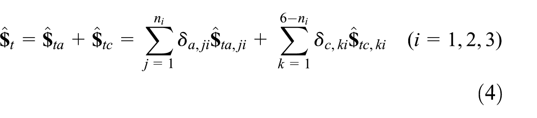
For the set of 1T2R tripod PKMs with prismatic actuators, each limb contains one prismatic actuator and two passive joints that can be decomposed into ni (1 ≤ ni ≤ 5) 1 degree-of-freedom (DOF) joint. Accordingly,
33
the twist space
Based on the screw subspace settings, one may let

where the two relations: “⊥” and “*” denote orthogonal and duality between screw and wrench, respectively.
Since the three limbs share the same terminal platform, the instantaneous twists of the platform can be written as the linear combination of all joint screws
where
Typically, the kinematic velocity analysis only considers the ideal motion of the platform, leading to

where
Equation (5) can be rewritten as

where
For the convenience of expressions, let


where
With the aid of equation (7), a dimensionally homogeneous Jacobian matrix of tripod PKMs can be formulated as
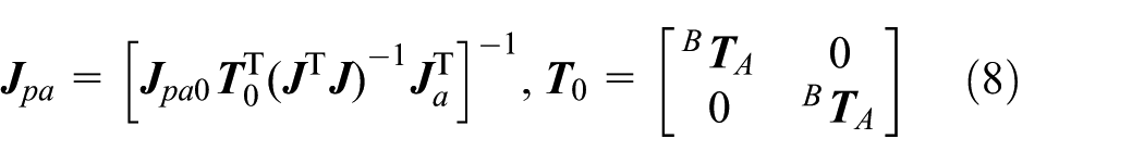
where
With the dimensionally homogeneous Jacobian matrix

where the operator “
From equation (9), it can be found that the value of De varies from zero to one, and a higher value indicates a better kinematic performance.
Eigenstiffness matrix formulation
In this section, the eigenstiffness matrix of the platform is derived based on a general kinetostatic model of tripod PKMs. To facilitate the modeling process, the following assumptions are made:
The base and the platform are assumed to be rigid due to their higher rigidities over other components.
The passive joints including the prismatic actuator assemblages are represented by 6-DOF virtual lumped spring units with equivalent stiffness coefficients locating at their geometric centers.
The limb structure is considered as a deformable spatial beam containing bending, extension, and torsion deflections, when subjects to the reactions from passive joints.
The frictions, dampings, and dynamic effects are neglected during the modeling process though they can be incorporated into the system governing equations with further efforts.
According to the kinematic features, the limb structures in a 1T2R tripod can be classified into two categories. For the first category, namely, case A, the limb length between the two passive joints is a constant value. For the second category, namely, case B, the limb length between the two passive joints is a varying value. The following will derive the finite element (FE) formulation for the limb assemblage of case A and case B, respectively.
Case A
As shown in Figure 2, the distance between the two passive joints Ai and Bi is constant when the limb undergoes kinematic motions. For this case, the limb assemblage can be simplified into a spatial limb beam constrained by two sets of 6-DOF virtual lumped springs. Assume that the equivalent linear/angular spring constants of the two passive joints are

Assembling scheme of an individual limb in case A.

FE model of an individual limb assemblage in case A.
The static equilibrium equation for the ith limb can be derived and expressed in the limb frame Ai–xiyizi as

where


where
Case B
As shown in Figure 4, the limb length between the two passive joints is changing when the limb undergoes kinematic motion. Herein, passive joint Bi consists of the nut which joins with the lead screw and servomotor, thus the prismatic joint can be driven by a lead screw linear actuator; Ci denotes the rear end of the limb body where the servomotor is installed and moving together.

Assembling scheme of an individual limb in case B.
Similar to case A, the limb assemblage is meshed into spatial beam elements with Ai, Bi, and Ci being the first, the (j + 1)th, and the (n + 1)th nodes, respectively.
As shown in Figure 5, an equilibrium equation can be formulated in the matrix form as equation (10). Herein, the general coordinates


where

FE model of an individual limb assemblage in case B.
Figure 6(a) and (b) demonstrates the deformation compatibility conditions between the limb and the platform as well as the base, respectively.

Two types of deformation compatibility conditions: (a) moving platform and the limb (b) the limb and fixed based.
Herein,


In the above equations,


where
Transforming equation (10) into the global coordinate system B–xyz, one may obtain

where

Figure 7 shows the force diagram of the platform. Herein,

Force diagram of the moving platform.
With Figure 7, the following static equations can be derived


where
Substituting equations (13) and (21) into equations (18) and (20), one may obtain the governing equations of the tripod in the matrix form

where
The stiffness matrix of the platform expressed in the body-fixed frame A–uvw can be further formulated as

where H = 18n + 24 is the dimension of the stiffness matrix.
The stiffness matrix of the platform

where
Based on equation (24), the stiffness matrix can be eigenscrew decomposed as

where

where
With the above eigenscrew decomposition, the stiffness matrix
Static performance formulation
Combining the local dexterity index De defined in equation (9) and the eigenscrew spring constant
The LDSI is defined as the following

From the above expression, it can be found that Dki has the same dimension with the stiffness matrix, while the local dexterity can be regarded as a dimensionless factor representing the kinematic effects on the platform’s rigidity in corresponding directions. In other words, LDSI can be interpreted as the corresponding spring constant multiplying with a dexterously weighting factor, considering both the kinematics and rigidity characters of a parallel mechanism.
Note that LDSI is a dimensional index. A dimensionless index GDSI is proposed and defined as the following

where
Obviously, a higher value of GDSI means a better global static performance of a tripod PKM. Furthermore, the most useful benefits of the proposed indices are that LDSI and GDSI consider both the kinematic dexterity and structural rigidity performances while avoiding the allocation of weighting factors between dexterity and stiffness during the design stage of a PKM. Reasonably, the proposed static performance indices can be adopted to conduct a comprehensive static performance optimization and enhancement of the tripod modules when both the kinematic and the stiffness characteristics need be simultaneously considered.
Analyses and discussions
For the sake of generality, a typical tripod PKM, Exechon PKM is taken as an example to demonstrate the performance evaluation with the proposed performance indices LDSI and GDSI. The basic structure of an Exechon PKM is depicted in Figure 8.
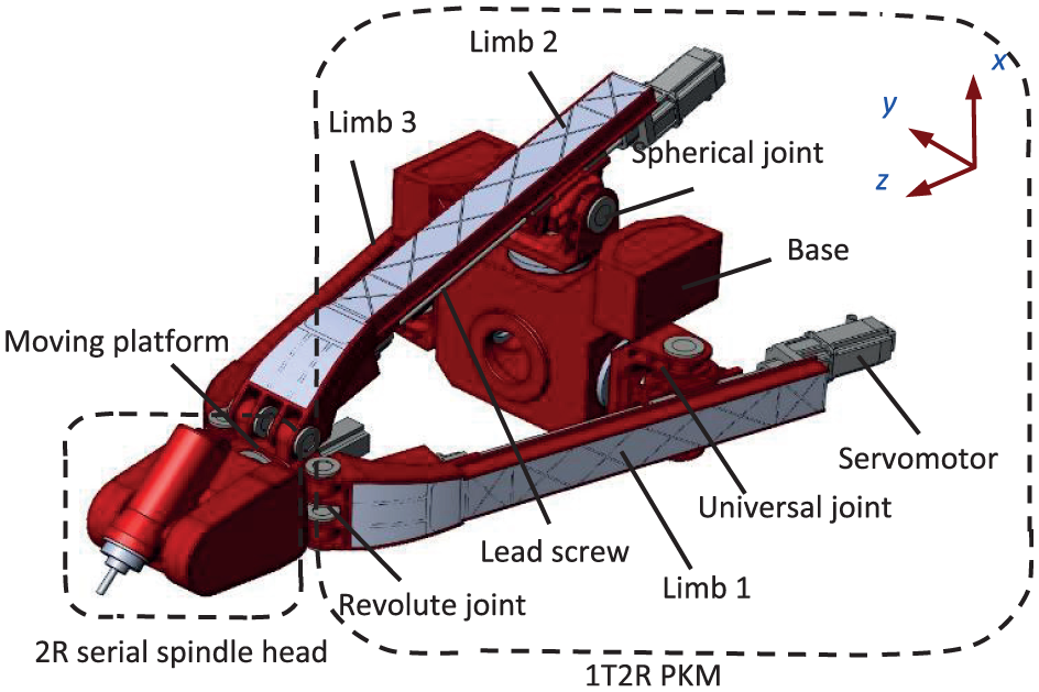
Structure of the Exechon machine tool.
The major geometric parameters of the example system are shown in Table 1. Herein, rp and rb represent the circumcircle radii of the platform and the base, respectively; qmin and qmax represent the minimum and the maximum distances between Ai and Bi; ψmax and θmax denote the maximum precession angle and nutation angle, respectively. Meanwhile, the stiffness coefficients of passive joints in their local frames calculated through ANSYS Workbench are listed in Table 2.
The geometric parameters of the Exechon PKM.

PKM: parallel kinematic machine.
The stiffness coefficients of passive joints in local frames.

Utilizing the above parameters, the following static performance predictions can be worked out.
Performance evaluation
In this subsection, Dki (i = 1, 2, …, 6) along the six screw spring directions are predicted throughout the entire workspace. The results are demonstrated as follows.
As can be seen from Figure 9, the performance indices are strongly position-dependent, in that Dki varies with ψ and θ as well as z. In addition, there exist dualities in the distributions of Dki, in that Dk1 and Dk6 are dual to each other, while Dk2 and Dk5, Dk3 and Dk4 consist two dual pairs. It can be found that Dki claims its maximum at the parallel position (ψ = 0°, θ = 0°), while its minimum appears at the boundary positions for different z coordinates. For example, at a given work plane of z = 1200 mm, Dk1 claims the maximal value of 1.090 × 10⁸ when ψ = 0°, θ = 0°, while achieving a minimal value of 1.670 × 10⁷ when ψ = 0°, θ = 36°.
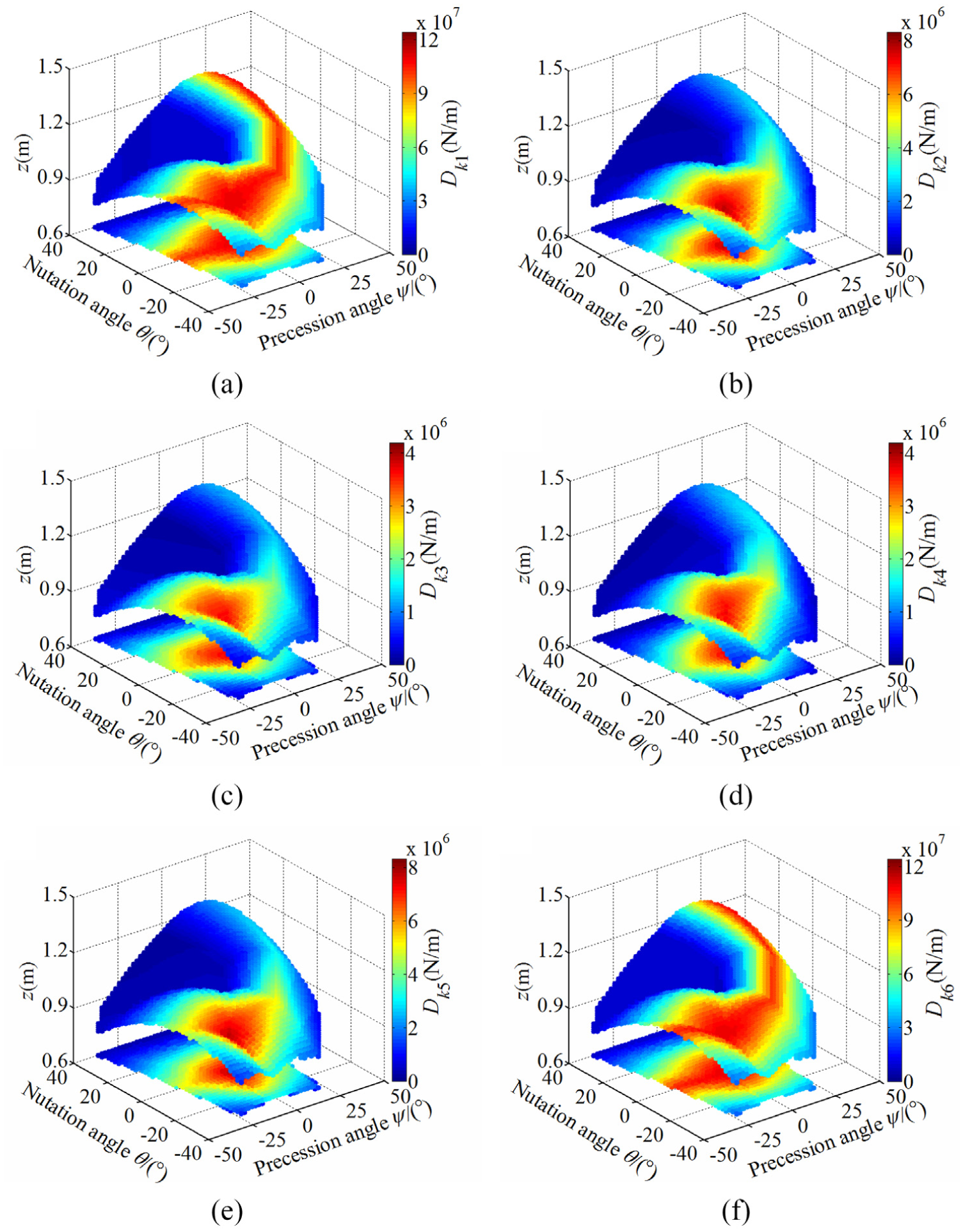
The distribution of Dki throughout the entire workspace: (a)–(f) along the six screw spring directions, respectively.
Further observations reveal that Dk1 and Dk6 are the largest among all the indices, while Dk3 and Dk4 are the smallest ones. This implies that the example Exechon PKM possesses a “strongest” static performance along the first and the sixth orders of the eigenscrew springs and a “weaker” static performance along the third and the fourth orders of the eigenscrew springs over the entire workspace. From this perspective, the static performance in the directions of the third and the fourth eigenscrew springs needs to be enhanced and paid more attentions during the design stage.
From the distributions of Dki throughout the entire workspace, an optimal region in which the Exechon PKM achieves “pleasant” static performance can be selected. Figure 10 shows the optimal region that Dki (i = 1, 2, 3) exceeds its mean value

The optimal region of the workspace for the Exechon PKM: (a)–(c) along the first three screw spring directions, respectively.
From Figure 10, it can be found that during the intervals of ψ = [−30°, +30°] and θ = [−26°, +26°], the static performance of the example system is more “pleasant.” Since there is no singularity within the workspace of the Exechon PKM, 16 this optimal workspace is recommended for practical operation. Further investigations reveal that there are very few differences between the volumes of the aforementioned optimal workspaces. To be more specific, the volume of optimal region of Dk1 is 0.0260 m*rad2 which claims 54.61% of the entire workspace; the volume of optimal region of Dk2 is 0.0224 m*rad2 which claims 47.15% of the entire workspace; the volume of optimal region of Dk3 is 0.0226 m*rad2 which claims 42.26% of the entire workspace.
Parameters analysis
To get insightful understanding of the effects of design parameters on the static performance, several key parameters such as the stiffness coefficients, structural, and dimensional parameters are taken as design variables to analyze their influences on the global performance with GDSI, respectively.
Figure 11 depicts the variations of the GDSI with respect to the stiffness coefficients of passive joints. For the convenience of analyses, assuming λsx is a scaling factor of kBsx shown in Table 2. In a similar way, λsy, λsz, λux, λuy, λuz, λuw, λrx, λry, λrz, λrv, and λrw are defined.

Variations of GDSI with respect to stiffness coefficients of the passive joints: (a) revolute joint, (b) universal joint, and (c) spherical joint.
Figure 11(a) shows the variations of GDSI with respect to the stiffness coefficients of revolute joint. It can be observed that GDSI keeps almost unchanged with respect to λry, λrz, and λrw, indicating that the stiffness coefficients kAry, kArz, and kArw barely influence on the global static performance. On the contrary, GDSI is significantly affected by the stiffness coefficient of kArx. In addition, GDSI is slightly affected by the stiffness coefficient of kArv. Therefore, it is recommendable to enhance the rigidity of the revolute joint in x-direction when designing such a revolute joint.
Figure 11(b) indicates that GDSI is sensitive to the change of stiffness coefficients of kBux and kBuz, while is less sensitive to the variation of kBuy and kBuw. Similarly, judging from Figure 11(c), GDSI decreases with the increment of kBsx and kBsz, while almost keeps unchanged with respect to kBsy. From these analyses, it can be concluded that the rigidity along x- and z-directions in the universal joint and the spherical joint must be dedicatedly designed to guarantee the desirable static performance for the Exechon PKM.
Figure 12 shows the variations of the GDSI with respect to the structural parameters of the limb body, in which the equivalent width w1 and height h1 of the cross section of limb body change with the variation intervals of [0.16, 0.24]m and [0.07, 0.11]m, respectively.
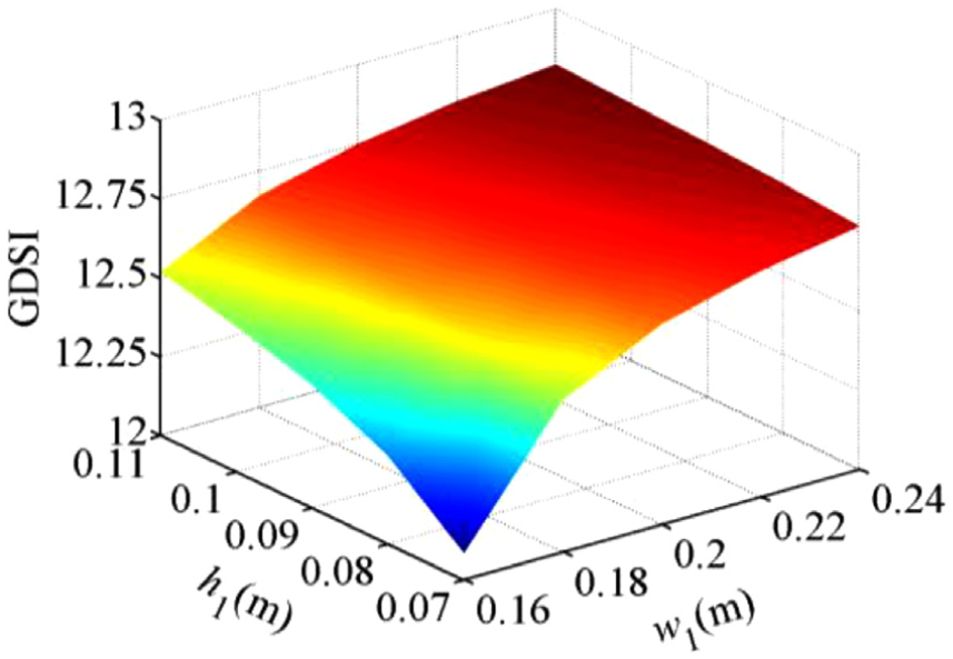
Variations of GDSI with respect to structural parameters of the limb body.
From Figure 12, it can be clearly seen that GDSI increases monotonously with the increments of the cross section of limb body, which is obviously coincident with the physical fact that the larger cross section leads to the higher rigidity of the limb body and thus enhances the static performance of the PKM. Further observation shows that GDSI of the PKM seems to more sensitive to the change of the equivalent width w1 of the limb body than that of the equivalent height h1. From this point of view, it is suggested to adopt some basic measures to enhance the width of the limb body when designing such a PKM.
Figure 13 depicts the variations of the GDSI with respect to dimensional parameters of the moving platform and fixed base, in which the radius of the moving platform rp and fixed base rb change with the variation intervals of [0.20, 0.40]m and [0.40, 0.80]m, respectively.

Variations of GDSI with respect to dimensional parameters of the moving platform and fixed base.
From Figure 13, it can be found that GDSI is not uniformly varying with the change of rp and rb, which can be brought by the inconsistent variations of the stiffness matrix and the local dexterity with the varying dimensional parameters of the PKM. Another observation can be seen that GDSI of the PKM claims the maximal value of 13.88 when the ratio of rp to rb is 0.25, while achieving a minimal value of 11.85 when the ratio of rp to rb is 1. This phenomenon may imply that a smaller ratio of rp to rb generates a higher value of GDSI, and thus, a better static performance of the PKM can be achieved.
Further comparative observations of above figures reveal that GDSI is more sensitive to the dimensional parameters than any other aforementioned design parameters of the PKM. From this point of view, the influence of design parameters on the static performance of the PKM can be roughly ranked from heavy to less as dimensional parameters, structural parameters, and stiffness coefficients. Therefore, it is recommendable to preferentially conduct the dimensional optimizations of the PKM before further parametric designs and optimizations on joint stiffness and limb structures.
Conclusion
Two improved comprehensive static performance indices LDSI and GDSI are proposed by combining a homogeneous dexterity formulation with an eigenstiffness expression to evaluate the static performance of tripod PKMs. This comprehensive index considers both the kinematic dexterity and static rigidity of the PKMs simultaneously, thus can be used to predict the static performance of tripod PKMs more intuitively.
With the proposed index of LDSI, the static performance of an Exechon PKM over its entire workspace is predicted and an optimal region with the workspace is selected for better operation effects.
With the proposed index of GDSI, the effects of several key design parameters on the global static performance are investigated to offer significant guidances for the parametric designs and optimizations of such a PKM module.
Footnotes
Appendix 1
Handling Editor: Yangmin Li
Declaration of conflicting interests
The author(s) declared no potential conflicts of interest with respect to the research, authorship, and/or publication of this article.
Funding
The author(s) disclosed receipt of the following financial support for the research, authorship, and/or publication of this article: This work was supported by the Open Fund of the State Key Laboratory for Manufacturing Systems Engineering (Xi’an Jiaotong University) with grant no. sklms2015004 and Open Fund of Shanghai Key Laboratory of Digital Manufacture for Thin-walled Structures with grant no. 2014001. T.T. would like to acknowledge for Innovation Research Fund for Postgraduates of Anhui University of Technology (grant no. 2015032).