
Abstract
The contour error cross-coupling control is very important to improve contour accuracy for the five-axis computer numerical control machine. The change in cutter orientation can cause the nonlinear motion of cutter tip, so the contour error calculation and compensation are very complex. For the five-axis computer numerical control machine with dual rotary tables, the forward kinematics model and inverse kinematics model are set up, and the influence laws of feed axis deviation to cutter tip deviation and cutter orientation deviation are studied. Then the simple and accurate calculation models for cutter tip contour error and cutter orientation contour error are established. Finally, the novel contour error cross-coupling control method based on kinematics model is developed. The experimental results show that the developed method can effectively improve contour accuracy of the five-axis computer numerical control machine.
Introduction
Five-axis computer numerical control (CNC) machine is an important processing equipment to realize high efficiency and high-quality machining for large and complex parts. For the five-axis CNC machine, the contour accuracy is the most important factor to determine machining accuracy. The improvement of contour accuracy relates to whether the dynamic characteristics of five feed axes are matched. 1 Because the servo drive system of CNC machine is very complex, it is difficult to match the actual dynamic performance between five feed axes, which will reduce the contour accuracy.
The research results show that the cross-coupling controller is a more effective way to improve the contour accuracy compared with the advanced single-axis servo controller.2–4 The key technology to realize cross-coupling control is to establish real-time contour error calculation model and contour error compensation amount calculation method.5–6
Yeh and Hsu 7 transformed the cross-coupling controller to the equivalent single-input single-output system with the introduced contour error transfer function and defined the distance from the actual cutter position to the tangent through the instruction position on the reference curve as contour error approximately. Zhong et al. 8 proposed a two-axis linear cross-coupling control scheme with first-in first-out interpolation buffer to overcome the nonlinearity of contour error, which is suitable for high-speed feed motion. Lee et al. 9 put forward a contour error vector control method with high precision for parametric curves, which is suitable for tracking curve with clear and simple function expressions. For space curve, Wang et al. 10 defined the distance from the actual cutter position to the line through the interpolation points of the current and the last sampling periods as the contour error. Zhao and Guo 11 achieved three-axis contour error coupling control with three plane coupling models.
Huo and Poo 12 developed a generalized cross-coupled control approach which can be applied for any free-form contour, including those defined only by a series of (x, y) coordinates similar to the reference inputs to CNC machines. Chen et al. 13 proposed six real-time contour error estimation methods for free-form parametric curves. Zhu et al. 14 developed a novel second-order approach for calculating contour errors of arbitrary contours. Zhang et al. 15 put forward a two-layered modeling and compensation scheme to reduce the contour error of three-dimensional motion control system. Rahaman et al. 16 developed an approach to combine the cross-coupled control with frequency modulated interpolation in high-speed machining.
In the three-axis CNC machine, the cutter tip position in the workpiece coordinate system is linear with the motion of each axis. Because without rotational axes, the contour error is only related to the cutter tip position and has nothing to do with the cutter orientation. 17 But for the five-axis CNC machine, the moving axes are used to control cutter tip position, while the rotational axes are used to control cutter orientation. However, the change in cutter orientation can cause nonlinear motion of cutter tip. 18 The coupling relationship between five feed axes is complex, and the nonlinear error cannot be compensated by the traditional three-axis cross-coupling controller.
In sum, the contour error calculation and compensation are very important to improve the contour accuracy and machining accuracy in the five-axis CNC machine. For the five-axis CNC machine with dual rotary tables, the forward kinematics model and inverse kinematics model are set up in the article. Then the contour error is divided into cutter tip contour error and cutter orientation contour error, and the simple and accurate calculation models are established. Finally, a novel contour error cross-coupling control method based on kinematics model is developed for the five-axis CNC machine.
Kinematics modeling for the five-axis CNC machine
As shown in Figure 1, in addition to three moving axes, the worktable of five-axis CNC machine is equipped with two rotational axes. The five-axis CNC machine can be looked as manipulator, and the kinematics models including forward kinematics model and inverse kinematics model can be built up using Denavit–Hartenberg (D–H) method. Furthermore, the influence laws of feed axis deviation to cutter tip deviation and cutter orientation deviation are studied in this section.

Five-axis CNC machine with dual rotary tables.
Transform between workpiece coordinate system and cutter coordinate system
As shown in Figure 2, the X-axis can make the worktable move along the left and right directions, the Y-axis can make the worktable move along the front and back directions, and the Z-axis can make the cutter move along the vertical direction; the A-axis can make the worktable rotate around X-axis, and the C-axis can make the worktable rotate around Z-axis.

Coordinate system of five-axis CNC machine with dual rotary tables.
According to the motion relativity, assume that the workpiece is fixed, and the bed and cutter can move. Furthermore, define the workpiece as base, the cutter as end actuator, the bed and transmission components as connecting rods, and the workpiece coordinate system as the base coordinate system. The origin of end actuator coordinate system is located in the cutter tip, and the direction is consistent with the workpiece coordinate system. So the movement order from the workpiece to the cutter is as follows: workpiece (base) → C-axis worktable → A-axis worktable →X-axis worktable → Y-axis worktable → bed → Z-axis spindle box → cutter (end actuator).
Suppose the movement amount of X-, Y-, Z-, A-, and C-axis as x, y, z, a, and γ, respectively; the cutter tip position in the workpiece coordinate system as P = [Px Py Pz] T ; and the cutter orientation in the workpiece coordinate system as unit vector O = [Ox Oy Oz] T . Using D–H method, each axis is fixed with a coordinate system. Then the coordinate system transformation matrix of each axis relative to the last axis can be obtained, respectively


Suppose the intersection of A- and C-axes be point Q, and its coordinate in the workpiece coordinate system be [Qx Qy Qz] T . So the transformation matrix from the workpiece coordinate system to the C-axis fixed coordinate system is

Consequently, the whole coordinate transformation matrix from the workpiece coordinate system to the cutter coordinate system can be obtained

Forward kinematics mode
The kinematics models of the five-axis CNC machine include forward kinematics model and inverse kinematics model. The task of forward kinematics model is to calculate the cutter tip position and cutter orientation in the workpiece coordinate system according to the movement amount of each feed axis. On the contrary, the task of inverse kinematics model is to obtain the movement amount of each feed axis according to the cutter tip position and cutter orientation. The forward and inverse kinematics transform relation is shown in Figure 3.

The transform relation between forward kinematic and inverse kinematic.
Suppose the cutter tip position and cutter orientation vector in cutter coordinate system be [0 0 0] T and [0 0 1] T , respectively. Then the cutter tip position in the workpiece coordinate system can be obtained
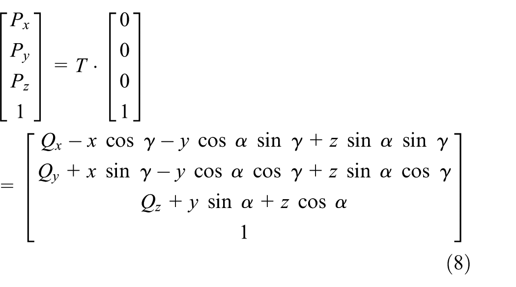
The cutter orientation vector in the workpiece coordinate system can be obtained

Cutter tip deviation and cutter orientation deviation
It can be seen from equation (8) that the x-component and y-component of the cutter tip coordinate in the workpiece coordinate system depend on not only three moving axes but also two rotational axes, while the z-component of the cutter tip coordinate depends on Y, Z moving axes and A rotational axis only. The cutter tip deviation can be calculated with partial derivative method according to equation (8)

It can be seen from equation (9) that the cutter orientation depends on two rotational axes only and has nothing to do with three moving axes. The relation between the cutter orientation deviation and rotational axes deviation can be obtained with partial derivative method

Consequently, the x-component and y-component of the cutter orientation deviation depend on the deviation of two rotational axes, while the z-component of the cutter orientation deviation depends on the deviation of A rotational axis only.
Inverse kinematics model
The cutter tip position depends on all the five axes, while the cutter orientation depends on two rotational axes only. Consequently, the movement amount of the five axes cannot be obtained according to cutter tip coordinate only. It is feasible to calculate the movement amount of the two rotational axes based on cutter orientation first, and then deduce the movement amount of the three moving axes based on cutter tip coordinate and the movement amount of two rotational axes.
The movement amount of the two rotational axes can be obtained according to equation (9)
Then the movement amount of the three moving axes can be obtained according to equation (8)

Contour error calculation model for the five-axis CNC machine
In five-axis machining, the actual movement amount of each axis can be measured by grating ruler, and then the actual cutter tip coordinate and cutter orientation vector in the workpiece coordinate system can be obtained with forward kinematics model. The reference tool-path and orientation trajectory are provided by the cutter location data files generated by the computer-aided manufacturing (CAM) post-processing. Then the cutter tip contour error and cutter orientation contour error can be defined and calculated, respectively.
Cutter tip contour error calculation model
The cutter tip contour error of the five-axis CNC machine is defined as the shortest normal distance from the actual cutter tip to the reference tool-path in the article. An approximate calculation model is proposed, which finds an interpolation point in the reference tool-path nearest to the actual cutter tip and looks the distance from the actual cutter tip to the nearest interpolation point as the cutter tip contour error.
As shown in Figure 4, suppose Pn(Px, Py, Pz) as the cutter tip interpolation point on current sampling period, Pn−i(Pix, Piy, Piz) is the ith interpolation point before point Pn. Suppose Pa(Pax, Pay, Paz) as the actual cutter tip position on current sampling period, and its coordinate can be calculated with forward kinematics model.
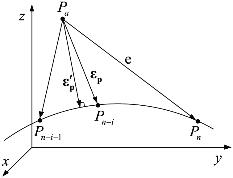
Cutter tip contour error calculation.
The tracking error on current sampling period is


According to definition, ε′ p is the true cutter tip contour error, which is very difficult to calculate. The introduced cutter tip contour error calculation model is shown as follows:
Calculate and compare the distance between Pa(Pax, Pay, Paz) and interpolation point Pn−6, Pn−5,…, Pn, Pn+1,…, Pn+6 one by one, and suppose
The point Pn−i is called the contour error compensation point in the article. The estimated cutter tip contour error is


On each sampling period, the actual contour error compensation point is on the reference tool-path, and the distance between the ideal compensation point and the actual compensation point is less than one interpolation interval, so the accuracy of the models is stable.
Influence of cutter orientation deviation on machining
When end milling flat or concave parts, the cutter orientation deviation will result in over-cutting. As shown in Figure 5, the cutter tip position is coincident when the cutter orientation is in ideal state or actual state, so the cutter orientation deviation does not lead to cutter tip deviation. However, over-cutting is produced because of cutter orientation deviation. The bigger the end milling cutter radius, the more serious the over-cutting.
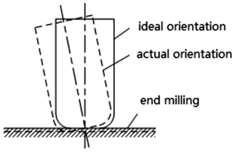
Over-cutting caused by cutter orientation deviation in end milling.
When side milling cavity parts, the cutter orientation deviation can also cause less cutting or over-cutting, as shown in Figure 6. There is no cutter tip deviation in Figure 6(a) and (b), but the cutter orientation deviation leads to less cutting or over-cutting. The greater the milling depth, the more serious the less cutting or over-cutting.

(a) Less cutting and (b) over-cutting caused by cutter orientation deviation in side milling.
In summary, the cutter orientation deviation will lead to serious machining errors in both end milling and side milling. So the calculation and compensation of cutter orientation deviation are helpful to reduce less cutting and over-cutting and improve the machining precision of the workpiece.
Cutter orientation contour error calculation model
On each interpolation point, the reference cutter tip coordinate corresponds to a reference cutter orientation vector. Only the actual cutter tip and cutter orientation are accordance with the corresponding relations strictly; the workpiece can be processed with high precision. In the cutter tip contour error calculation model, the contour error compensation point is found. To achieve better coordinated motion between the moving axes and rotational axes, the reference cutter orientation vector on the contour error compensation point is used to calculate the cutter orientation contour error in the article.
The cutter location data are shown in Figure 7. Suppose L as the reference tool-path; point Pn as the interpolation point on current sampling period; Pa and Oa as the actual cutter tip point and cutter orientation vector, respectively; Pn−i as the interpolation point nearest to Pa, that is, the contour error compensation point. Suppose point Pn and Pn−i correspond to the cutter orientation vector On and On−i, respectively, then PaPn is the tracking error and PaPn−i is the approximate cutter tip contour error.
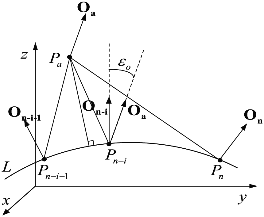
The cutter tip coordinate and cutter orientation vector.
In this article, the cutter orientation contour error is defined as the angle between the cutter orientation vector On−i on contour error compensation point and the actual cutter orientation vector Oa, which is represented by εo in Figure 7. The definition model is novel. Two calculation methods are set up for calculating the cutter orientation contour error:
Method 1
Since the cutter orientation is a unit vector, the end point of the vector must be located on unit sphere if the starting point of the vector is the origin. And the end point trajectory is defined as the cutter orientation trajectory. As shown in Figure 8, suppose On−i = [Oix Oiy Oiz] T as the reference cutter orientation vector on the contour error compensation point Pn−i, and suppose Oa = [Oax Oay Oaz] T as the actual cutter orientation vector on the current sampling period.

The cutter orientation contour error calculation.
Then the cutter orientation contour error is

When expressed in arc, the size of εo is equal to the length of spherical arc between the two end points. Because εo is very small, the spherical arc length is approximately equal to the corresponding chord, that is

Method 2
According to vector algebra theory, the following can be obtained

So εo can be calculated as follows

In conclusion, equations (19) and (21) can be used to calculate the cutter orientation contour error.
Contour error cross-coupling control method based on kinematic model
Cross-coupling control method of the five-axis CNC machine
The cutter tip position depends on all the five axes, while the cutter orientation depends on two rotational axes only. Based on the kinematic model and the introduced contour error calculation models, the multi-input and multi-output (MIMO) cross-coupling control method is developed for contour error compensation as shown in Figure 9.

MIMO contour error cross-coupling control scheme.
The actual dynamic performance of five servo axes cannot be exactly the same, so it is difficult to achieve satisfactory contour accuracy in machining without cross-coupling control. The essence of the developed MIMO contour error cross-coupling control scheme is to compute the contour error compensation amount for each axis to enhance contour accuracy with decoupling algorithm, without changing the servo position control loop of each axis. From the viewpoint of control, the single-axis coordinate control of machine tool is changed to closed-loop contour control, which is more conducive to improve the contour accuracy of feed system.
The idea of cutter tip contour error compensation is to make the actual cutter tip as close as possible to the reference tool-path on each sampling period, while the idea of cutter orientation contour error compensation is to make the actual cutter orientation as close as possible to the cutter orientation on contour error compensation point.
The calculation steps of the developed contour error cross-coupling control method are as follows:
Measure the actual position of each axis with grating ruler on each sampling period and obtain the actual cutter tip coordinate and cutter orientation vector by forward kinematic operation.
Couple the contour error: find the contour error compensation point by comparing the distance between the actual cutter tip and the interpolation points stored in interpolation buffer and calculate the cutter tip contour error with equation (17) and cutter orientation contour error with equation (19) or equation (21).
Decouple the contour error: first, calculate the rotational axes movement amount for contour error compensation according to equation (12); then calculate the moving axes movement amount for contour error compensation according to equation (13).
Calculate the tracking error for each axis according to interpolation data and actual cutter position and then add the movement amount for contour error compensation to the tracking error.
Calculate the position control amount for each axis and send to servo feed system to achieve coordinated motion.
Tracking error control and contour error cross-coupling control
Suppose the actual measurement position of each axis be xa, ya, za, aa, and γa, and suppose the tracking error be ex, ey, ez, ea, and eγ on each sampling period. The actual cutter tip coordinates in the workpiece coordinate system can be calculated with equation (8)

Suppose the contour error compensation point be [Pxr Pyr Pzr] T , the corresponding reference cutter orientation vector be [Oxr Oyr Ozr] T . Then calculate the cutter tip contour error with equation (17) and the cutter orientation contour error with equation (19) or (21). The movement amount εx, εy, εz, εa, and εγ for contour error compensation can be obtained by inverse kinematics operation with equations (12) and (13).
For each axis, add the movement amount for contour error compensation to the tracking error on each sampling period

The total position control amounts for each axis when adopting proportional–integral–derivative (PID) position controller are as follows

where KP, KI, and KD are proportional coefficient, integral coefficient, and differential coefficient in axis position controller, respectively.
Contour error cross-coupling control experiments
The CNC controller of the developed five-axis test table is made up of industrial personal computer (IPC) and programmable digital signal processing (DSP) control card. The IPC and DSP control card communicate through USB2.0. Both the interpolation period and sampling period are 4 ms. As shown in Figure 10, the X-, Y-, and Z-axes all adopt Yaskawa AC servomotors and ball screw transmission and make use of linear grating sensors to measure actual worktable position on each sampling period. The A- and C-axes adopt Yaskawa AC servomotors and worm gear transmission pair and make use of circular grating sensors to measure actual worktable position. The speed control, interpolation algorithm, tracking error control, contour error calculation, and compensation control are realized in the programmable DSP motion control card.

The developed five-axis test table.
In the five-axis machining, both the reference tool-path and the cutter orientation on each point must be described separately. In the verification experiment, the reference tool-path is a spiral curve as shown in Figure 11. The parameter equation is as follows
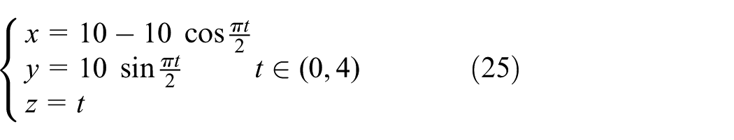

The reference tool-path.
The cutter orientation on each point is a unit vector in the five-axis machining, and the end point of the vector must be located on unit sphere if the starting point of the vector is the origin. The end point trajectory is defined as the cutter orientation trajectory in the article, and the reference cutter orientation trajectory is the intersection of unit sphere and cylinder in the experiment, as shown in Figure 12. The parameter equation of the end point trajectory is as follows
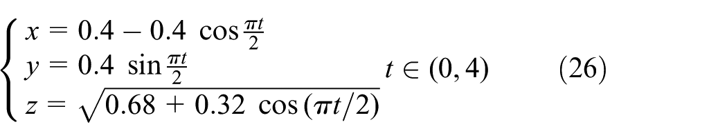

The reference cutter orientation trajectory.
The PID parameters of five axes after turning with particle swarm optimization algorithm are shown in Table 1.
PID parameters of position controller.

The effectiveness of the contour error cross-coupling control method is verified by comparing the final contour accuracy.
The cutter tip contour accuracy comparison: as shown in Figure 13, when not adopting the developed contour error cross-coupling control method, the maximum cutter tip contour error is 355.4 µm and the mean value of cutter tip contour error is 197.5 µm; while the maximum cutter tip contour error is 299.7 µm, the mean value of cutter tip contour error is 124.8 µm when adopting the developed method.
The cutter orientation contour accuracy comparison: as shown in Figure 14, when not adopting the developed contour error cross-coupling control method, the maximum cutter orientation contour error is 8.3 mrad and the mean value of cutter orientation contour error is 4.1 mrad; while the maximum cutter orientation contour error is 6.4 mrad, the mean value of cutter orientation contour error is 3.1 mrad when adopting the developed method.
When not adopting the developed contour error cross-coupling control method, the maximum tracking error of each axis is 70 µm (ex), 67 µm (ey), 15 µm (ez), 2.8 mrad (ea), and 2.6 mrad (eγ) individually; when adopting the developed contour error cross-coupling control method, the maximum tracking error of each axis is 65 µm (ex), 61 µm (ey), 13 µm (ez), 2.5 mrad (ea), and 2.4 mrad (eγ) individually. The comparison results show that the maximum tracking error of each axis is reduced slightly. The reason is that the contour error is reduced when adopting the developed control method, and the actual cutter tip position is closer to the reference tool-path on each sampling period.

Cutter tip contour accuracy.

Cutter orientation contour accuracy.
The experimental results show that the developed contour error cross-coupling control method is very effective in reducing contour error and improving contour accuracy on the same working circumstances.
Conclusion
For the five-axis CNC machine, the moving axes are used to control cutter tip position, while the rotational axes are used to control cutter orientation. However, the change in cutter orientation can cause nonlinear motion of cutter tip. The coupling relationship between five feed axes is complex, and the traditional three-axis cross-coupling controller cannot be used in the five-axis CNC machine. This article presents a contour error cross-coupling control method to achieve five-axis coordinated motion based on forward kinematic model and inverse kinematic model.
Taking the five-axis CNC machine with dual rotary tables as example, on the basis of building forward kinematics model and inverse kinematics model, the influence laws of feed axis deviation to cutter tip deviation and cutter orientation deviation are researched.
For the five-axis CNC machine, the contour error is divided into cutter tip contour error and cutter orientation contour error. The cutter tip contour error is related to all the five axes, while the cutter orientation contour error is only related to two rotational axes. The simple and accurate calculation models for cutter tip contour error and cutter orientation contour error are established.
The novel MIMO contour error cross-coupling control method is developed. The compensation for cutter tip contour error makes the actual cutter tip as close as possible to the reference tool-path on each sampling period, while the compensation for cutter orientation contour error makes the actual cutter orientation as close as possible to the cutter orientation on the contour error compensation point. The experimental results show that the developed method can improve contour accuracy effectively.
Footnotes
Academic Editor: Xichun Luo
Declaration of conflicting interests
The author(s) declared no potential conflicts of interest with respect to the research, authorship, and/or publication of this article.
Funding
The author(s) disclosed receipt of the following financial support for the research, authorship, and/or publication of this article: The authors are grateful to the Project of the National Natural Science Foundation of China (no. 51105236).