
Abstract
For the rotary motion of a rolling bearing implemented by bearing components under geometric constraints, the rotational accuracy of assembled bearing should also be the result of interaction among geometric errors of bearing components. Therefore, it is significant to research the relationship between geometric errors of bearing components and rotational accuracy of assembled bearing for the design and prediction of bearing accuracy. An accuracy prediction method is proposed to study how the geometric errors of bearing components affect the radial runout of outer ring of cylindrical roller bearings in this article. Furthermore, the calculation model for the orbit of outer ring center is established from which the radial runout of outer ring can be predicted while dimension and roundness errors of raceways and rollers are given arbitrarily. Theoretical algorithms with two typical shapes of outer raceway are deduced to verify the prediction method. In addition, a test on the radial runout of outer ring in a cylindrical roller bearing is performed. The results indicate that prediction results are in good agreement with experimental and analytical results.
Keywords
Introduction
The rolling bearing, as a rotary support part of mechanical equipments, is widely used in aerospace, precision machine tools, disk, and other precision mechanical systems. The rotational accuracy of assembled bearing directly determines the precision of the mechanical system.1–3 Geometric error is always present to varying degrees in manufactured bearing components, and it is one of the important factors which result in the motion error of rolling bearing. 4 Therefore, it is crucial to investigate the influence of geometric errors of bearing components on rotational accuracy of assembled bearing, which is helpful to the design and production of high-precision rolling bearing.
At present, the research on the performance of rolling bearings is mainly concerned on non-repetitive runout, orbit of shaft center, dynamic performance, and radial runout. Noguchi and colleagues5–10 proposed a two-dimensional computational model for non-repetitive runout of a ball bearing considering roundness error of the outer raceway and diameter error of balls and analyzed the influences of geometric errors in outer raceway and balls, number of balls, diameter difference, and disposition of balls on non-repetitive runout of a ball bearing. Liu et al. 11 established a two-dimensional computational model on non-repetitive runout of high-speed angular contact ball bearings based on a 5-degree-of-freedom (DOF) quasi-static model and studied the influences of the waviness of bearing components on non-repetitive runout of the bearing. Yuan et al. 12 developed a two-dimensional computational model for non-repetitive runout of a ball bearing considering geometric errors in raceways and balls. The effects of geometric errors in raceways and balls and number of balls on the non-repetitive runout of the bearing were analyzed. Tada 13 established a three-dimensional model to calculate non-repetitive runout of angular contact ball bearings based on the waviness of bearing components and studied the influences of waviness in the raceway grooves and balls on the non-repetitive runout of the bearing. Jang et al. 14 characterized the source of non-repetitive runout of a ball bearing and the transmission of non-repetitive runout from the ball bearing to the disk and investigated the effect of viscoelastic damping in the transmission path on the non-repetitive runout of the bearing. Li and Mao 15 developed a 5-DOF static model for non-repetitive runout of deep groove ball bearings and analyzed the effects of roundness error in raceway grooves and diameter difference and disposition of balls on non-repetitive runout of the bearing. Okamoto et al. 16 established a two-dimensional model to predict orbit of shaft center of ball bearings based on roundness error of the outer raceway and analyzed the influences of number of balls, dimension error of balls, and roundness error of the outer raceway on the size and shape of the orbit of shaft center. Tandon and Choudhury 17 presented a new analytical model for calculating vibration frequency of rolling bearing considering single defect of rolling elements or rings and studied the effects of the defect of bearing components on the vibration of rolling bearings. Ono and colleagues18,19 established a calculation model for the vibration of a ball bearing based on waviness of bearing components and analyzed the influences of the waviness in the raceways and balls on the vibration of the ball bearing. Wang et al. 20 deduced an expression of nonlinear contact forces of a roller bearing and presented a 4-DOF transient dynamics model of roller bearings considering radial clearances and waviness of the bearing. The vibration behaviors of the rotor roller bearing system were investigated. Chen et al.21,22 developed a one-dimensional model for calculating the radial runout considering roundness error of raceways and diameter error of the rollers and presented a static model for the load performance in a cylindrical roller bearing based on diameter error of the rollers. The effects of diameter differences among the rollers on the load performance and the radial runout in a cylindrical roller bearing are investigated. Wang et al. 23 presented a two-dimensional model to predict geometric accuracy of a cylindrical roller bearing considering roundness error of the inner or outer raceway. Bhateja et al. 24 established a two-dimensional prediction model for rotational accuracy of hollow roller bearings considering dimension difference of rollers. In previous research,25–28 the effects of roundness error of the inner and outer raceways on rotational accuracy of a cylindrical roller bearing were investigated, respectively. A computational model for the radial runout of inner ring based on roundness error of the inner raceway was established, and a computational model for the radial runout of outer ring considering roundness error of the outer raceway was developed. In those current methods for rotational accuracy of cylindrical roller bearings, only form error of a bearing component was considered. However, the rotational accuracy of assembled bearing resulted from the interaction among geometric errors of the inner raceway, outer raceway, and rollers in the geometric constraints of the bearing. Therefore, it is necessary to propose a prediction method for rotational accuracy of cylindrical roller bearings considering the dimension and form errors in the raceways and rollers.
A prediction method for the radial runout of outer ring in cylindrical roller bearings, taking into account dimension and form errors of the inner raceway, outer raceway, and rollers, is seldom reported. In this article, a method to predict the radial runout of outer ring in cylindrical roller bearings is proposed considering geometric errors of the raceways and rollers. The proposed method could predict the radial runout of outer ring under given or known dimension and form errors of the inner raceway, outer raceway, and rollers. The prediction method could be used to establish the relationship between geometric errors of bearing components and rotational accuracy of assembled bearing.
Prediction method for the radial runout of outer ring in cylindrical roller bearings
According to international measurement standards of rotational accuracy of rolling bearings, the inner ring is fixed and the outer ring rotates at very slow speed when the radial runout of outer ring is measured. To make the raceways contact with the rollers, a small measuring load is applied to the outer ring, which cannot make bearing components cause obvious elastic deformation. The vertical displacement of the outer ring is measured as the radial runout value of the outer ring. According to the above measurement conditions, a prediction method for the radial runout of outer ring in cylindrical roller bearings is presented, which is based on the following assumptions:
The elastic deformation of bearing components is not considered. The measuring load on the bearing is too small to make bearing components cause obvious elastic deformation. Therefore, the elastic deformation of bearing components is not taken into account in the proposed prediction method.
There are no axial form error in the raceways and rollers. The radial runout is an important index for cylindrical roller bearings. To this end, a cylindrical roller bearing is presented as a two-dimensional flat surface model. Thus, the axial form error of bearing components are not considered.
There is no relative slip between rollers and raceways. The skidding of rollers often occurs in high-speed roller bearings. Therefore, the relative slip between rollers and raceways is not taken into account.
The roller is uniformly distributed in the circumferential direction. The influence of the clearance between rollers and the cage pocket on the position angle of rollers is neglected.
The radial runout of outer ring is a main index to measure rotational accuracy of assembled bearing. According to standard definition of the radial runout of outer ring, the inner ring is fixed, and the outer ring rotates. The outer ring rotates several revolutions; the difference between the maximal and minimal radial runout values of the outer ring is the radial runout of outer ring. To obtain the radial runout of outer ring, a method to predict the radial runout of outer ring is presented. Its calculation process is as follows: first, the parameters of the bearing are given, and the rotational step of the outer ring is set. According to the characterization method of geometric error, geometric errors of bearing components are given or reconstructed. Second, the outer ring rotates a rotational step. On the basis of the geometric model of the bearing, the radii of raceways and rollers are obtained. Third, the radial runout value of the outer ring is calculated. The central coordinates of the outer raceway are calculated by the calculation model for runout orbit of bearing center, and its vertical displacement is the radial runout value of the outer ring when the outer ring rotates a rotational step. Finally, the outer ring continues to rotate a rotational step, and so on, the outer ring rotates several revolutions; the radial runout value of the outer ring is obtained every rotational step. The difference between the maximal and minimal radial runout values of the outer ring is the radial runout of outer ring.
Characterization method of geometric error
Only dimension and roundness errors in the raceways and rollers are taken into account. Geometric error of a bearing component can be expressed with the addition of dimension and roundness errors, as shown in equation (1). Hereinto, the roundness error item is described by the Fourier series in a polar coordinate system
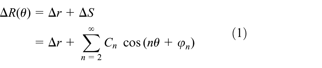
where
The dimension and roundness errors of bearing components can be given arbitrarily or reconstructed by profile data of bearing components. The dimension error value of a manufactured bearing component in different circumferential positions is measured by the bearing comparator. The dimension error of the bearing component is equal to the average value of dimension error values in different circumferential positions. The roundness error of a manufactured bearing component is expressed by several harmonic components. Hereinto, it is the key problem to obtain harmonic orders, amplitudes, and phase angles. The profile data of a bearing component are collected by the roundness instrument, as shown in Figure 1. The amplitudes and phase angles of harmonic components are obtained with Fourier transformation of the profile data, as shown in Figures 2 and 3. Thus, the roundness error function of a bearing component is restructured by the 15 harmonic components with larger amplitude. The profile radius is equal to the addition of mean value of raw profile data, the first harmonic component, and the roundness error. Comparing the reconstruction profile data with the raw profile data, the reconstruction profile data are consistent with the raw profile data, as shown in Figure 4. The result indicates the correctness of the reconstruction method of geometric error.
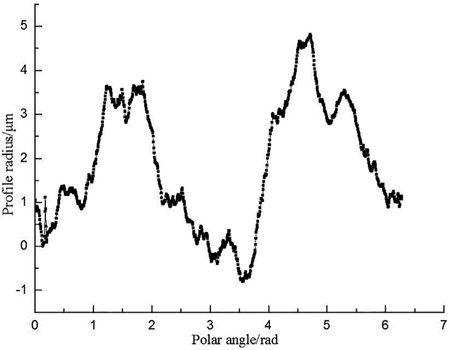
Raw profile data of an inner raceway.

Spectrum analysis of raw profile data.
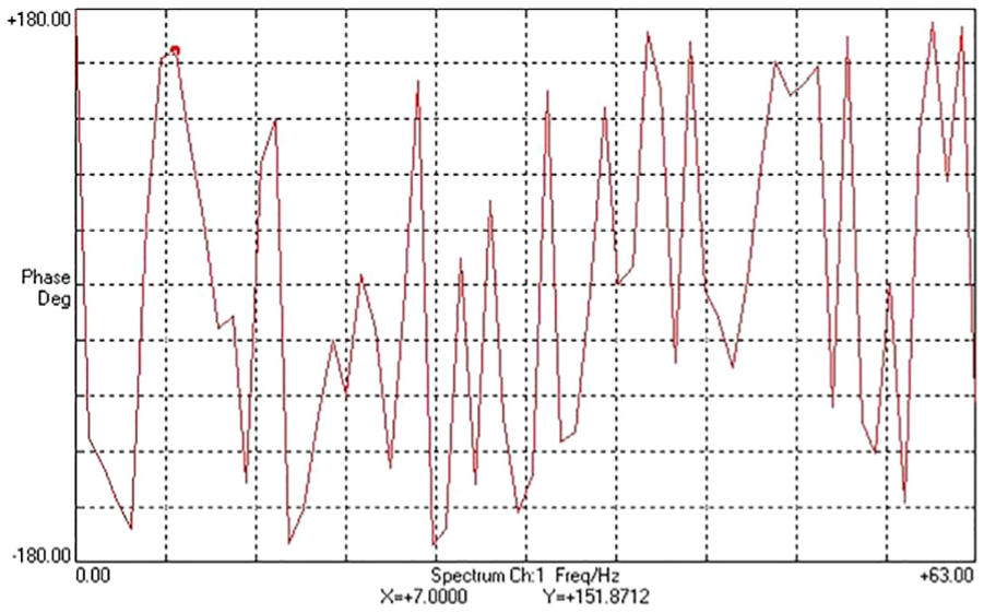
Phase frequency response curve of raw profile data.

Comparison between raw profile data and reconstruction profile data.
Geometrical model of cylindrical roller bearings
A fixed global Cartesian coordinate system (X, Y) is set up at the center of the bearing with its origin O coinciding with the center of the inner raceway, as shown in Figure 5. A moving Cartesian coordinate system (xrj, yrj) is fixed to the center of the jth roller, which translates with the jth roller and is always parallel to the global coordinate (X, Y), respectively. Another moving Cartesian coordinate system (xe, ye) is fixed to the center of the outer raceway, which translates with the outer ring and is always parallel to the global coordinate (X, Y), respectively.

Geometrical model of a cylindrical roller bearing.
Due to geometric errors in manufactured bearing components, the raceways and rollers are shown as non-circular curves, as indicated in Figure 5. It is known that the inner ring is fixed and the outer ring rotates. As for the above assumptions, the outer ring only moves in the horizontal and vertical directions. The outer ring and rollers move down by gravity. The rollers above the bearing move to contact with the inner raceway along the radial direction. The outer ring moves to contact with the rollers above the bearing and eventually reaches a steady state. Xe is the horizontal displacement of the outer ring, and Ye is the vertical displacement of the outer ring.
When the outer ring rotates an arbitrary angle α anticlockwise, the jth roller revolves around the center of the inner raceway anticlockwise; in the meantime, the jth roller revolves around its axis clockwise. Finally, the jth roller rolls to a new location. The spin angle, the revolution angle, and the position angle of the jth roller are calculated by equations (2)–(4), respectively


where
The radii of the inner raceway, outer raceway, and the jth roller


where d is the raceway diameter, the subscript i denotes the inner raceway, the subscript e denotes the outer raceway, and the subscript r denotes the rollers.
Calculation model for the runout orbit of bearing center
Due to the influences of radial clearance and geometric error of bearing components, the outer raceway contacts with partial rollers above the bearing when the outer ring rotates an arbitrary angle α. Thus, the outer ring is located in a stable position. In order to obtain the stable position of the outer ring, a calculation model for the runout orbit of bearing center is established. Its calculation steps are as follows: first, the central coordinates of the rollers are computed when the rollers above the bearing contact with the inner raceway. Second, the contact statuses of the outer raceway are obtained when the outer ring is located in different positions. Third, the central coordinates of the outer raceway are determined from some different positions of the outer ring.
Calculation of the central coordinates of rollers
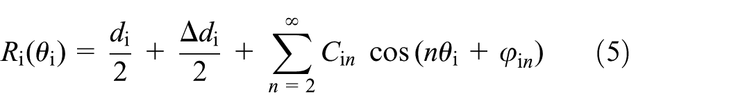
When the outer ring rotates an angle α, the rollers move around the circumference to a new position. In this case, the rollers above the bearing contact with the inner raceway. In order to obtain the central coordinates of the rollers, it is assumed that the rollers move along the radial direction at a given step until they contact with the inner raceway. Therefore, the distances between the center of the inner raceway and the center of rollers are obtained. From Figure 6, it can be seen that the central coordinates of the jth roller can be calculated through the distance. Hereinto, the critical problem is to judge whether the jth roller contacts with the inner raceway when the roller is located in a position. For this purpose, a calculation method for the shortest distance between the jth roller and the inner raceway, which is used to determine the position relationships (contact, separation, interference) between the rollers and the inner raceway.

Geometrical relationship between a roller and inner raceway: (a) when the jth roller is located in the first quadrant and point A is located above the line o rj O, (b) when the jth roller is located in the first quadrant and point A is located below the line o rj O, (c) when the jth roller is located in the second quadrant and point A is located above the line o rj O, and (d) when the jth roller is located in the second quadrant and point A is located below the line o rj O.
When the outer ring rotates an arbitrary angle α, and the jth roller moves to a certain location, the geometrical relationship between the jth roller and inner raceway is indicated in Figure 6. The distance between any point A on the surface of the jth roller and any point C on the inner raceway is expressed by equation (8)

where

where CO is the radius of point C, which is calculated by putting the polar angle of point C into equation (5), as shown in equation (11).


where
When the jth roller is located in the first quadrant and point A is located above the line orjO, the geometrical relationship between the inner raceway and the jth roller is indicated in Figure 6(a), and

where

When the jth roller is located in the first quadrant and point A is located below the line orjO, the geometrical relationship between the jth roller and the inner raceway is indicated in Figure 6(b), and

When the jth roller is located in the second quadrant and point A is located above the line orjO, the geometrical relationship between the inner raceway and the jth roller is indicated in Figure 6(c), and
When the jth roller is located in the second quadrant and point A is located below the line orjO, the geometrical relationship between the inner raceway and the jth roller is indicated in Figure 6(d), and
The distance
Contact status of the outer raceway in different positions
According to the above calculation, it is known that the rollers above the bearing contact with the inner raceway when the outer ring rotates an angle α. There are different rollers which contact with the outer raceway when the outer ring is located in different positions. In order to obtain the contact status of the outer raceway, a computational method for the shortest distance between the outer raceway and the surface of the jth roller is presented. The position relationships between the rollers above the bearing and the outer raceway are determined through the shortest distance, thus the contact statuses of the outer raceway are obtained in different positions of the outer ring.
The outer ring rotates an angle α, and it is located in a certain position. The geometrical relationship between the rollers above the bearing and the raceways is shown in Figure 7. The distance between any point D on the outer raceway and any point B on the surface of the jth roller is expressed by equation (16)

where

where

where

Geometrical relationship between rollers and raceways: (a) when the jth roller is located in the first quadrant and point B on the surface of the jth roller is located above the line orjoe, (b) when the jth roller is located in the first quadrant and point B on the surface of the jth roller is located below the line orjoe, (c) when the jth roller is located in the second quadrant and point B on the surface of the jth roller is located above the line orjoe, and (d) when the jth roller is located in the second quadrant and point B on the surface of the jth roller is located below the line orjoe.
When the jth roller is located in the first quadrant and point B on the surface of the jth roller is located above the line

where


where
When the jth roller is located in the first quadrant and point B is located below the line

When the jth roller is located in the second quadrant and point B is located above the line

When the jth roller is located in the second quadrant and point B is located below the line

The central coordinates of the rollers which contact with the inner raceway are known. The central coordinates of the outer raceway are given. When the angle
Similarly, a position relationship between each roller above the bearing and the outer raceway is obtained, and the rollers which contact with the outer raceway are determined. Thus, the contact status of the outer raceway is obtained when the outer ring is located in a certain position. In the same way, the contact statuses of outer raceway are obtained in different positions.
Central coordinates of the outer raceway
In order to identify the stable position of the outer ring from different positions, a stable criterion of the outer ring is presented as follows: (1) there is at least one roller contacting with the raceways on any side of ye-axis. When the outer ring is located in a certain position, only one roller contacts with the inner and outer raceways, as shown in Figure 8(a). In this case, the outer ring cannot keep balance, and it is not stable. When two rollers which are located on one side of ye-axis contact with the raceways, as shown in Figure 8(b), the sum of forces on the outer ring cannot be zero. Therefore, the outer ring is not stable in this position. When there is at least one roller contacting with the raceways on any side of ye-axis, the outer ring can keep balance. (2) There is no interference between the outer raceway and rollers above the bearing. To obtain the stable position of the outer ring, a movable region of the outer ring is given. But the given movable region of the outer ring is larger than the real movable region of the outer ring. Therefore, there is interference between the outer raceway and rollers when the outer ring is located in some positions. Obviously, there is no interference among bearing components when the outer ring is located in the stable position. (3) The horizontal displacement of the outer ring is minimum. There are many positions of the outer ring which satisfy the above two conditions. In these positions, the center of the outer ring is closest to the Y-axis while the horizontal displacement of the outer ring is minimum. In this position, the center of gravity of the outer ring is the lowest. Therefore, the outer ring is stable in the position where the horizontal displacement of the outer ring is minimum. Two positions of the outer ring are shown in Figure 9. The horizontal displacement of the outer ring is less in the first position than in the second position. Therefore, the first position is the stable position of the outer ring.
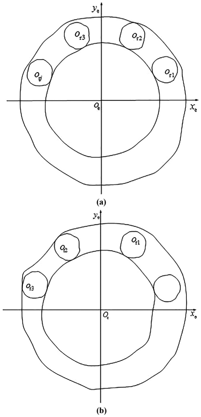
Contact status of the outer ring: (a) when only one roller contacts with the inner and outer raceways and (b) when two rollers which are located on one side of ye-axis contact with the raceways.
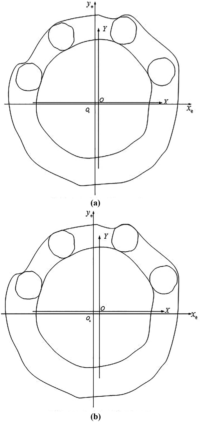
Contact status of the outer ring: (a) the first position of the outer ring and (b) the second position of the outer ring.
When the outer ring is located in different positions, the contact statuses of the outer raceway are obtained. The stable position of the outer ring, where its contact status satisfies all conditions of the stable criterion, is identified from different positions of the outer ring. Thus, the central coordinates of the outer ring are obtained. The vertical displacement of the outer ring is the radial runout value of the outer ring when the outer ring rotates an angle α.
Validation of prediction method
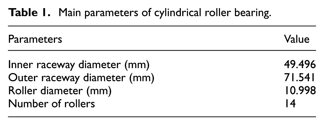
To validate the proposed prediction method, the cylindrical roller bearings with two different shapes of the outer raceway are selected as the research objective to calculate the radial runout value of the outer ring. Aiming at two different shapes of the outer raceway, the analysis algorithms for the radial runout value of the outer ring are derived, respectively. Meanwhile, the proposed prediction method is validated by comparison with experimental results and prediction results. The main parameters of the cylindrical roller bearing with code NU208 are as indicated in Table 1.
Main parameters of cylindrical roller bearing.
Validation of prediction method with outer raceway shape for a circle
The shapes of bearing components are without geometric error. For the existence of radial clearance, the outer raceway contacts only with the two uppermost rollers without load, as indicated in Figure 10. The analysis algorithm for the radial runout value of the outer ring is deduced as follows.

Geometrical model with shapes of bearing components for a circle.
When the outer ring rotates an angle α, the geometrical model is shown in Figure 10. According to the geometrical relationship of the bearing, the distance

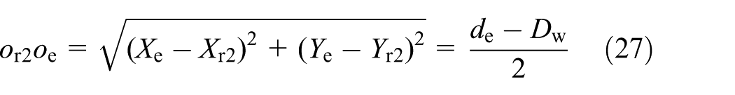
where Xr1, Yr1 and Xr2, Yr2 are the central coordinates of the two uppermost rollers, which are calculated by equations (28) and (29), respectively


where
The central coordinates of the outer raceway are calculated by solving equations (26) and (27) simultaneously. Therefore, the radial runout value of the outer ring is obtained when the outer ring rotates an angle α.
To validate the proposed prediction method, the cylindrical roller bearings with two different radial clearances are used to calculate the radial runout values of the outer ring by the proposed prediction method and the deduced analysis algorithm, respectively. The outer ring rotates one revolution, and the analytical and prediction results are indicated in Figure 11. Comparing prediction results with analytical results, the biggest relative error is 0.046%.

Comparison between prediction results and analytical results: (a) radial clearance for 0.045 mm and (b) radial clearance for 0.065 mm.
Validation of prediction method with outer raceway shape for an ellipse
The shape of the outer raceway is an ellipse, and the shapes of other bearing components are a circle. The outer raceway contacts only with the two uppermost rollers without load while the amplitude of roundness error in the outer raceway is less, as indicated in Figure 12.

Geometrical model with shapes of the outer raceway for an ellipse.
When the outer ring rotates an angle α, the geometrical model is shown in Figure 12. It is assumed that the curvature center of the ellipse is approximate to geometrical center of the ellipse. According to the geometrical relationship of the bearing, the distance


where


where a and b are the semi-major and semi-minor axes of ellipse, respectively.

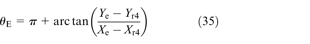
The central coordinates of the outer raceway are calculated by solving equations (30) and (31) simultaneously through the Newton–Raphson method. Hence, the radial runout value of the outer ring is obtained when the outer ring rotates an angle α.
To validate the proposed prediction method, the cylindrical roller bearings with two different ellipse shapes of the outer raceway are selected as the research objective to calculate the radial runout values of the outer ring by the proposed prediction method and the deduced analysis algorithm, respectively. The outer ring rotates one revolution; the analytical results and the prediction results are shown in Figure 13. Comparing prediction results with analytical results, the biggest relative error is 0.056%.

Comparison between prediction results and analytical results: (a) semiminor axis for 35.767 5 mm and (b) semiminor axis for 35.769 5 mm.
The effectiveness of the proposed prediction method is verified by analytical results. The proposed prediction method can accurately forecast the radial runout of the outer ring in cylindrical roller bearings.
Experimental verification of prediction method
Taking NU208-type cylindrical roller bearing as an example, bearing components are shown in Figure 14(a), and the assembled bearing is shown in Figure 14(b). To obtain the radial runout of the outer ring, the inner ring is fixed to the mandrel, and the mandrel is supported by the centers. The radial runout of outer ring is measured by bearing deflection instrument, as shown in Figure 15. A dial gauge is fixed to the bench of bearing defection instrument, and its probe presses on mid-ship section of the outer ring in the vertical direction. The outer ring rotates several revolutions slowly, and the maximum and minimum runout values of the outer ring are obtained through the dial gauge. Thus, the radial runout of outer ring is obtained.

NU208-type cylindrical roller bearing: (a) bearing components and (b) assembled bearing.

Measuring the radial runout of outer ring.
To obtain the prediction results for the radial runout of outer ring, the dimension and roundness errors of bearing components are reconstructed by profile data of bearing components based on the method in section “Characterization method of geometric error.” The profile radii of bearing components are obtained. The proposed prediction method is implemented, and the prediction results are compared to experimental results, as shown in Table 2. The relative error is about 10%. The result shows that the proposed prediction method is accurate and efficient.
Comparison of results.

Simulation examples
Taking NU208-type cylindrical roller bearing as an example, as shown in Table 1, numerical examples are provided to verify the universality of prediction method discussed above.
Figure 16 shows the radial runout value of the outer ring when the outer ring rotates 540°; hereinto, the amplitude of roundness error in the outer raceway is 1 µm, and the harmonic order of roundness error is 10. The maximal radial runout value of the outer ring is 0.02373 mm, and the minimal radial runout value of the outer ring is 0.02154 mm. The radial runout of outer ring is 2.191 µm.

Radial runout value of the outer ring with roundness error in the outer raceway.
Figure 17 shows the radial runout value of the outer ring when the outer ring rotates 540°; hereinto, the amplitude of roundness error in the inner raceway is 1 µm, and the harmonic order of roundness error is 8. The maximal radial runout value of the outer ring is 0.02332 mm, and the minimal radial runout value of the outer ring is 0.02152 mm. The radial runout of outer ring is 1.805 µm.

Radial runout value of the outer ring with roundness error in the inner raceway.
Figure 18 shows the radial runout value of the outer ring when the outer ring rotates 540°; hereinto, the amplitude of roundness error in the roller is 1 µm, and the harmonic order of roundness error is 15. The maximal radial runout value of the outer ring is 0.02309 mm, and the minimal radial runout value of the outer ring is 0.02248 mm. The radial runout of outer ring is 0.606 µm.

Radial runout value of the outer ring with roundness error in all rollers.
Figure 19 shows the radial runout value of the outer ring when the outer ring rotates 540°; hereinto, the amplitude of roundness error in the roller, the inner raceway, and the outer raceway is 0.5, 1, and 1 µm, respectively, and the harmonic order of roundness error in the roller, the inner raceway, and the outer raceway is 4, 8, and 9, respectively. The maximal radial runout value of the outer ring is 0.02437 mm, and the minimal radial runout value of the outer ring is 0.01989 mm. The radial runout of outer ring is 4.474 µm.

Radial runout value of the outer ring with roundness error of bearing components.
The radial runout values of the outer ring are calculated by the proposed prediction method when there are roundness errors in the inner raceway, the outer raceway, and the rollers. The universality of the proposed prediction method is verified by numerical examples. Therefore, the prediction method can forecast the radial runout of outer ring with random geometric errors of the inner raceway, outer raceway, and rollers.
Conclusion
A method to predict the radial runout of outer ring in cylindrical roller bearings is proposed. The method can be used to predict the rotational accuracy of assembled bearing after bearing components with dimension and roundness errors are assembled.
The calculation method for the shortest distance between the non-circular raceway and the non-circular surface of a roller is proposed, and a calculation model for the runout orbit of bearing center considering geometric errors of bearing components is established, which can be used to calculate the runout orbit of the center of the outer raceway.
The prediction results are in agreement with experimental and analytical results. The results indicate the effectiveness of the proposed prediction method. Meanwhile, the applicability of the prediction method is verified with roundness errors in the inner raceway, the outer raceway, and the rollers by numerical examples. Therefore, the prediction method is suitable for calculating the radial runout of outer ring in cylindrical roller bearings, which provides a theoretical method for the accuracy prediction and design of cylindrical roller bearings.
Footnotes
Handling Editor: Hiroshi Noguchi
Declaration of conflicting interests
The author(s) declared no potential conflicts of interest with respect to the research, authorship, and/or publication of this article.
Funding
The author(s) disclosed receipt of the following financial support for the research, authorship, and/or publication of this article: The authors gratefully thank the National Natural Science Foundation of China (no. 51375148), the Natural Science Foundation of Henan Province of China (no. 162300410064), and the Project of Basic and Advanced Technology Research of Henan Province of China (no. 142300413217) for financial support. This work was also supported by the Key Research Program of the Higher Education Institutions of Henan Province (no. 15A460022) and the Program for Innovative Research Team (in Science and Technology) in University of Henan Province (no. 15IRTSTHN008).