As the important infrastructure of power transmission systems, the power transmission lines are vulnerable during the peak power transmission periods. They usually meet many faults that may cause large area blackouts because of heavy loads. This article proposes a supervisory control strategy to promote the detection and restoration of power transmission failures during the peak or off-peak periods. The faults occurring in power transmission lines can be detected, and fault restoration schemes can be selected by supervisors. Moreover, the architecture of distributed control systems is proposed to perform message switching among supervisors. A coordination protocol that is executed by each supervisor is proposed to selected fault restoration schemes. The proposed strategy can not only detect and restore power transmission failures but also improve the utilization rate of available loads in power transmission systems. The proposed distributed control systems and coordination protocol are modeled by synchronized Petri nets. The correctness of fault restoration is verified using the mathematical methods of Petri nets. Finally, the complexity of the proposed distributed control systems and coordination protocol is discussed, and a real-world example is given.
As an important energy, electric energy is transmitted from remote power stations to users by traditional power transmission systems (PTSs) that are generally composed of many distributed electrical substations (ESs) and power transmission lines. However, the power transmission lines are vulnerable. They usually suffer faults because of heavy loads, human damage, equipment damage, and natural disasters. These faults may cause large area blackouts. Battery energy storage systems1 can be installed at ESs for load leveling and relay protection.2 If faults occur in ESs, their battery energy storage systems can continually supply electric power for their output. Nevertheless, the electric power supply is temporary because the capacities of battery energy storage systems are limited. Therefore, the faults should be detected and restored urgently.
Smart grids are safe and reliable power systems, which usually are constructed by coalescing distributed control systems (DCSs) into traditional PTSs.3 Faults occurring in traditional PTSs should be detected and restored by DCSs. Therefore, reliable and safe DCSs are extreme importance for fault detection and restoration in smart grids.
Expert control systems can be used to play the roles of DCSs for fault detection and restoration in traditional PTSs. Minakawa et al.4 present a fault diagnosis expert system for electric power systems. Chien et al.5 propose a Bayesian network for fault diagnosis on distribution feeders based on expert knowledge. Ma et al.6 construct a multi-back propagation expert system to implement fault diagnosis in power systems. In these methods, the faulty states of power systems can be detected according to the knowledge of their proposed expert systems. The expert knowledge is updated and optimized by learning system information. However, the system information may also be interfered because of fault occurrences. Furthermore, the reliability and security of expert control systems may also be affected.
Multi-agent methods have high function reconfigurable characteristics, which can be used to implement DCSs. Momoh7 designs a control system based on multi-agent methods to perform fault detection and restoration for a navy ship system. Xu and Liu8 propose a multi-agent architecture to implement fault restoration in micro-grids. Each bus in a micro-grid is assigned with a node agent. Tong et al.9 present a DCS with a fault restoration algorithm. The faults can be located by collecting wide-area information in the DCS. In these methods, the faults are detected and restored by agents. Nevertheless, these DCSs are neither formally modeled nor verified by any formal method.
The function blocks (FBs) of IEC 6149910 provide a standard structure to model DCSs. A FB is an encapsulated algorithm unit that can be designed as a device. Higgins et al.11 present a DCS by the form of FBs to perform power system automation. Vyatkin et al.12 prove the feasibility of using decentralized multi-agent control logic to perform fault detection and restoration in power distribution networks based on FBs. The presented method is simulated at a MATLAB-based simulation environment. However, FBs cannot provide any formal verification method to verify the correctness of these presented DCSs.
As a class of formal paradigms, Petri nets13 are also used to perform fault detection and restoration in discrete event systems. Antonio et al.14 concern with an online model-based fault diagnosis of discrete event systems with interpreted Petri nets. Lira et al.15 focus on the modeling design of flexible assembly system control. The proposed method constructs a sequence of steps for fault detection based on Petri nets. Dimitri and Edouard16 present an approach to perform fault detection and identification of discrete event systems based on Petri nets. Mahulea et al.17 study the effect of fluidization on fault diagnosis using purely logic Petri net models. Renganathan and Bhaskar18 discuss a Petri net approach to achieve fault diagnosis in a typical bottle-filling plant. Lefebvre19 concerns fault diagnosis for discrete event systems based on partially observed Petri nets by analyzing observation sequences. Cabral et al.20 propose a Petri net approach to perform online fault diagnosis for discrete event systems based on the construction of a Petri net diagnoser. Basile et al.21 investigate a procedure for fault diagnosis of labeled time Petri net systems. The fault diagnosis is performed using a modified state class graph. Wang et al.22 propose an online fault diagnosis approach for timed discrete event systems based on timed Petri nets in which all transitions are partitioned into observable and unobservable.
The DCSs of smart grids are typical discrete event systems. Researchers also use Petri nets to study fault detection and restoration in power systems. Ghainani et al.23 present a fault diagnosis system in power systems based on fuzzy timing Petri nets. Shi et al.24 mainly investigate fault diagnosis issues of micro-grids using timed-colored Petri nets. Zhang et al.25 investigate the temporal constraint between event occurrences in power systems. The proposed method is suitable for online fault diagnosis in large-scale power systems. Sun et al.26 use fuzzy Petri nets to build fault diagnosis models aiming to accurately diagnose faults if the incomplete alarm information of protective relays and circuit breakers is detected. Wang et al.27 present a fault diagnosis program to facilitate accurate fault judgment, and the fault diagnosis methods are optimized using comprehensive knowledge representation. Calderaro et al.28 report a method to detect and localize faults in smart grids. The behavior of smart grids is formalized using Petri nets. The faults can be computed by incidence matrix operations. However, the structures of the proposed Petri net models depend on the number of trip thresholds.28 The incidence matrixes of Petri net models are complex for large-scale smart grids. The fault restoration and formal description are also neglected. Especially, they do not consider the special environments of peak periods. This article uses Petri nets to formally model traditional PTSs, and the proposed methods are verified using the mathematical methods of synchronized Petri nets during the peak power transmission periods.
In smart grids, the output loads of ESs are generally inconstant along with the fluctuations of electricity demands that are affected by the peak periods of work, feast days, holidays, climate changes, and so on. It is necessary to balance the electricity demands for guaranteeing stable power transmission during the peak periods. One can forecast the peak periods and schedule the power transmission. However, it is difficult to forecast faults in traditional PTSs since the fluctuations of electricity demands may result in many faults. Furthermore, it is complex to detect and restore faults during the peak periods. Salat and Osowski29 present an approach to locate faults in high-voltage power transmission lines during the peak periods. The presented approach depends on the application of support vector machine. Evrenosoglu and Abur30 provide a fault location approach for three terminal lines during the peak periods. The proposed algorithm is tested using MATLAB-based environments. These approaches only focus on the fault location and accuracy improving problems. They do not consider fault restoration during the peak periods. The formal verification for their methods is also neglected.
By reviewing the aforementioned methods, many methods consider fault diagnosis, detection, location, or restoration in traditional PTSs. Some studies focus on the fault detection and location at some special environments. However, they do not consider fault restoration during the peak periods. The formal verification for their methods is also neglected. The losses caused by faults are generally more serious during the peak periods. Therefore, all faults should be detected and restored during the peak and off-peak periods.
In this article, the structures of traditional PTSs are simplified into three layers and are formally modeled using synchronized Petri nets. Each ES is controlled by a supervisor. If faults occur in the input lines of the ES during peak or off-peak periods, the faults can be detected by the supervisor. Moreover, each ES can be preconnected with other ESs. A fault restoration set of preconnected ESs can be selected to collectively restore faults if the faults are detected, where the fault restoration only considers the power transmission restoration but not the failure equipment restoration. Furthermore, the architecture of DCSs based on traditional PTSs is proposed to perform message switching among supervisors. A coordination protocol is proposed to perform the selection of fault restoration sets for each fault during the peak or off-peak periods. Finally, the correctness of fault detection and restoration is verified using the mathematical methods of synchronized Petri nets. The main contributions of this article are concluded as follows:
The structures of traditional PTSs are simplified and formally modeled using synchronized Petri nets. The purpose is to propose simple structures for promoting the behavior analysis of traditional PTSs.
A methodology is proposed to design DCSs based on the simplified traditional PTSs, and the communication lines of the designed DCSs are optimized. Moreover, an algorithm is proposed to control the communication between any two nodes. The designed DCSs can control their traditional PTSs.
A fault detection strategy is provided based on the supervisory control theory. It can detect faults that occur in power transmission lines. We also propose a coordination protocol to perform the restoration of power transmission failures during peak and off-peak periods. The proposed coordination protocol can improve the utilization of available loads in traditional PTSs by computing fault restoration sets.
Finally, the correctness of fault restoration is verified using the mathematical methods of synchronized Petri nets.
The rest of this article is organized as follows: The basics of synchronized Petri nets are introduced. The structure of traditional PTSs is simplified and formally modeled using synchronized Petri nets. The structures of supervisors and DCSs for fault detection and restoration are proposed. Furthermore, a coordination protocol is proposed to choose fault restoration sets. Moreover, an example is given, and the complexity of the proposed DCSs and coordination protocol is discussed. Finally, we conclude this article.
Basics of synchronized Petri nets
We assume that the readers are familiar with the basics of Petri nets. Only some key concepts of synchronized Petri nets are provided. More details of Petri nets can be found in Murata31 and David and Alia.32
A typical discrete event control system is composed of four units: a plant, a supervisor, the sensor readings, and the control actions,33 as shown in Figure 1. The plant and supervisor are two discrete event systems, which are assumed to run concurrently. The supervisor is used to monitor and control the plant to avoid forbidden operations. The states of plant can be transmitted to supervisor by the sensor readings. The control events of supervisor can be transmitted to plant by the control actions. An external state change of a discrete event system is called an external event (it can be considered as a control event and transmitted by a control action), and an internal state change of a discrete event system is called an internal event.32 More details of discrete event control systems can be found in David and Alia.32
A discrete event control system.
Synchronized Petri nets are a class of event-driven Petri nets in which the firing of a transition is triggered by a specific external event.32 They can be used to describe discrete event control systems.
In a synchronized Petri net , , t is associated with an event (t is said to be receptive to the event). Transition t is enabled at a marking M if , . The enabling degree of t for marking M, denoted by q or , is the integer q such that
If , transition t is q-enabled. If t is enabled and its associated event occurs, t will continuously occur q times.
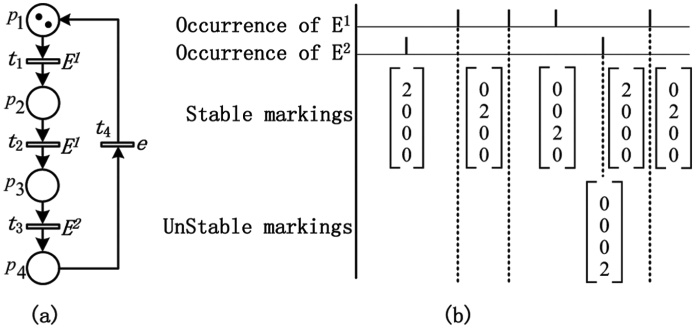
Figure 2(a) shows a synchronized Petri net that contains two external events and , where transitions and are receptive to event , transition is receptive to event , and transition is receptive to always occurring event e. Figure 2(b) shows the evolution of markings, where the event sequence is . The input and output matrixes are
(a) A synchronized Petri net and (b) the evolution of markings.
In Figure 2(a), only transition is 2-enabled at the initial marking . The synchronized Petri net is only receptive to event . This means that the occurrence of any other event will not affect marking . Therefore, the first event of sequence Z does not alter anything. As soon as event occurs, fires twice. We can obtain a new marking . At marking , only transition is 2-enabled. When the second occurrence of event in sequence Z occurs, also fires twice. A new marking is obtained. At marking , only is 2-enabled. When the third occurrence of event occurs, it does not alter anything. When event occurs, fires twice, and a new marking is obtained. At marking , is 2-enabled, and fires immediately since is receptive to always occurring event e. The synchronized Petri net returns to marking . Let . Then, . We have
In this example, marking is unstable since transition is receptive to an always-occurring event e. At marking , transitions and will fire if event occurs.
Traditional PTSs
A traditional PTS generally is a complex power network, which is composed of many distributed ESs and power transmission lines. In order to facilitate its formal description, we simplified its structure as follows: The distributed ESs are hierarchically simplified into three layers, that is, high-, medium-, and low-voltage ESs, according to the three power transmission processes, that is, transmission, subtransmission, and distribution, as shown in Figure 3. The transmission power voltages are gradually declined from high voltages to low voltages during transmission processes. Therefore, it can be concluded that the electric power is transmitted from high-voltage ESs to medium-voltage ESs and is continually transmitted from the medium-voltage ESs to low-voltage ESs.
A traditional power transmission system.
In a traditional PTS, each ES can be abstracted to a place, and the electric power transmission between two ESs can be abstracted to a transition with an always-occurring event e. The power transmission from an ES to other ESs can be discretized and abstracted to the token transmission from a place to other places. Therefore, a traditional PTS can be modeled by using synchronized Petri nets.
Definition 1
Let be a synchronized Petri net with . Synchronized Petri net is a traditional PTS if
, , and are the sets of high-, medium-, and low-voltage ESs, respectively, , , and .
is the set of power transmission operations.
is the set of power transmission arcs.
, , and such that and .
, (a) and such that and and (b) there only exist a transition and a place such that and .
, there only exist a transition and a place such that and .
is a mapping that assigns a number of electric power loads to a power transmission arc.
is a set of external events.
is a mapping. , , where e is the always-occurring event.
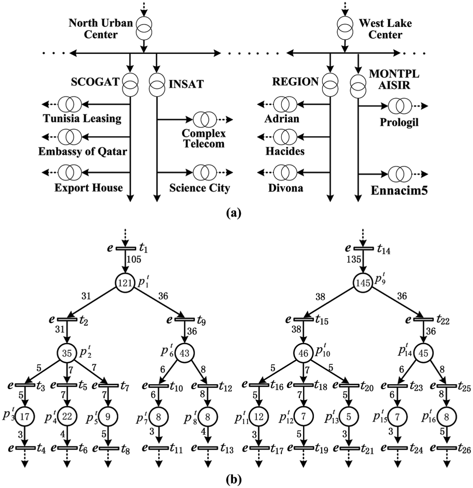
Figure 4(a) shows a traditional PTS and Figure 4(b) shows its synchronized Petri net model with an initial marking. For example, the three ESs of “North Urban Center,”“SCOGAT,” and “Tunisia Leasing” are modeled as places , , and , respectively. The power transmission between ESs “North Urban Center” and “SCOGAT” is modeled as transition with an always-occurring event e and the power transmission between ESs “SCOGAT” and “Tunisia Leasing” is modeled as transition with an always-occurring event e. The electric power (represented as tokens) is transmitted from to by and is continually transmitted from to by .
(a) A traditional PTS and (b) the synchronized Petri net model of the traditional PTS.
In a traditional PTS , , p has input loads (denoted as ) that are transmitted from its upstream ES with its input lines. ES p also has output loads (denoted as ) that are transmitted to its downstream ESs with its output lines. We have
The loads of are the available loads of p (denoted as ). Note that can be supplied to other ESs.
For any ES, its input and output lines usually meet faults because of heavy loads, human damage, equipment damage, and natural disasters, especially during the peak periods. If a fault occurs in its input lines, its electric power cannot be transmitted from its upstream ES and a large area blackout will occur. For example, if a fault occurs in the input lines of “Export House” in Figure 4(a), this means that cannot fire to add tokens to in Figure 4(b). A large area blackout may occur in “Export House” and its downstream ESs.
In a traditional PTS , , ES may be preconnected with other ESs by emergence power transmission lines and electric switches that are opened in initial states. The preconnected ESs can supply their available loads to by closing related electric switches. Therefore, power transmission failures can be restored and large area blackouts can be carried off in . The electric switches can also be abstracted to the places of synchronized Petri nets. They are closed if their corresponding places have enough tokens. Otherwise, the electric switches are opened. The selection of preconnected ESs for should consider the implementation costs because of the geographical distances between and its preconnected ESs. Furthermore, the preconnected ESs should have enough power to be supplied to if a fault occurs in the input lines of .
Definition 2
Let be a traditional PTS with and , , be two ESs. ES is called a solution of if is preconnected with by emergence power transmission lines.
Definition 3
Let be a traditional PTS with and be a synchronized Petri net with . Synchronized Petri net is a safe PTS if
is the set of electric switches with .
is the set of emergence power transmission operations.
, where
and such that is a solution of .
is a mapping, where
.
is a mapping, where
Figure 5 shows the part of a safe PTS that is based on the traditional PTS depicted in Figure 4(b). It is constructed by an ES and its two solutions and , where the power supply from (respectively, ) to is controlled by electric switch (respectively, ). Let be a marking, where is the initial marking of . The electric power can be supplied from (respectively, ) to if (respectively, ).
The two solutions and of .
In a safe PTS, its faults can be restored by solutions. However, before that, the faults should be detected and the corresponding electric switches should be closed.
Fault detection
In order to detect and restore faults in a safe PTS, , is monitored and controlled by a supervisor that contains a fault detector, a fault controller, and a network message interface, as shown in Figure 6.
The structure of supervisors.
Fault detector: It contains an electric current sensor to monitor the input lines of . If a fault occurs during the upstream power transmission processes, the electric currents of the input lines will disappear. The fault can be detected by the electric current sensor because of the electric current disappearance in the input lines. Then, a “Fault” message will be sent to an internal fault controller.
Fault controller: If a “Fault” message is received from the fault detector, the solutions of will close corresponding electric switches by a network message interface.
Network message interface: It is used to communicate with other supervisors.
All supervisors can construct a DCS by connecting their network message interfaces. Any two supervisors can communicate with each other. The constructed DCS is a typical discrete event system. Similarly, all supervisors can be modeled as places, and the message transmission among supervisors can be modeled as transitions in synchronized Petri nets. The messages transmission from a supervisor to other supervisors can be modeled as the token transmission from a place to other places.
Definition 4
Let be a safe PTS with and be a synchronized Petri net with . Synchronized Petri net is a DCS of the safe PTS if
, , and are the sets of supervisors such that supervisor is associated with ES , , .
is the set of message switching operations, where , .
is the set of communication arcs such that
, such that , , , and .
, such that and are associated with the ESs and , respectively. Then, such that , , , and if such that and .
is a mapping that assigns a message to a communication arc.
is a set of external events, where , , and , is receptive to event if and .
is a mapping that assigns an external event to a message switching operation.
Figure 7 shows the structure of a DCS that is based on the traditional PTS depicted in Figure 4(b), where supervisors are used to control ESs , respectively. For example, supervisor can communicate with supervisors , , and , respectively. Similarly, supervisor can communicate with supervisors , , , and , respectively. Supervisors can also be represented by Petri nets with initial markings. The proper initial marking of the DCS can be set after all structures and initial markings of supervisors are integrated.
A distributed control system.
Definition 5
Let , , and be three ESs and , , and be three supervisors such that ESs , , and are controlled by supervisors , , and , respectively, where . Supervisor is called the upper supervisor of if and , denoted as . Supervisor is called the top supervisor of if , , and , denoted as .
For example, in Figure 7, we have , , and . Similarly, , , and .
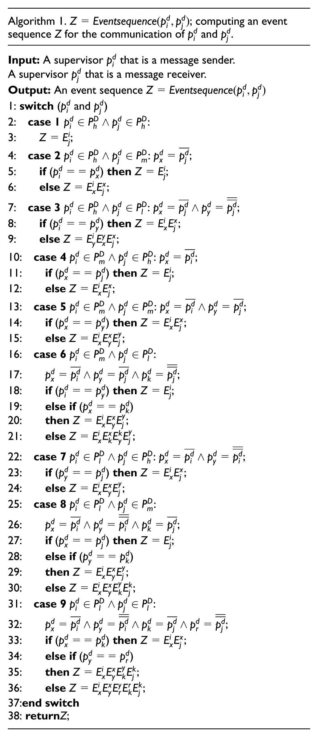
According to definition 4, , is receptive to an external event. Therefore, the communication path from a supervisor to supervisor is controlled by an event sequence Z that is generated by the fault controller of supervisor with Algorithm 1.
Algorithm 1. ; computing an event sequence Z for the communication of and .
Input: A supervisor that is a message sender.
A supervisor that is a message receiver.
Output: An event sequence
1: switch ( and )
2: case 1:
3: ;
4: case 2: ;
5: if () then;
6: else;
7: case 3: ;
8: if () then;
9: else;
10: case 4: ;
11: if () then;
12: else;
13: case 5: ;
14: if () then;
15: else;
16: case 6:
17: ;
18: if () then;
19: else if ()
20: then;
21: else;
22: case 7: ;
23: if () then;
24: else;
25: case 8:
26: ;
27: if () then;
28: else if ()
29: then;
30: else;
31: case 9:
32: ;
33: if () then;
34: else if ()
35: then;
36: else;
37:end switch
38: returnZ;
In Algorithm 1, an event sequence can be computed if two supervisors are assigned. There are nine cases for the two assigned supervisors according to their geographical locations, where has three cases, that is, , , or , and is similar with .
Property 1
Let be a DCS with . such that , then can communicate with according to the external event sequence Z, denoted as , where Z is computed by .
Proof
In a DCS, , can communicate with its upper supervisor . is the set of all upper supervisors of . Similarly, , can communicate with its upper supervisor . is the set of all upper supervisors of . Therefore, can communicate with its top supervisor . Moreover, , can communicate with . Therefore, such that , can communicate with . Algorithm 1 proposes a function to compute the event sequence .
In Figure 7, we assume that a message will be sent from supervisor to supervisor . This means that the initial marking and the finial marking should be
The input and output matrixes of the DCS depicted in Figure 7 are
In this DCS, we have according to , , , and , where an external event sequence Z is computed by Algorithm 1, that is, .
At marking , transition is enabled and is associated with an external event . If occurs, fires and a message is sent from to . A new marking is obtained. At marking , we have a marking after , , and fire along with the occurrences of external events , , and in event sequence Z, respectively. Therefore, a message is transmitted from to according to an external event sequence .
According to the initial marking and transition sequence , making can be verified as follows
where . According to and transition sequence , marking can also be verified as follows
where . Similarly, supervisor can send messages to supervisor . Supervisors and can also exchange messages with each other.
Coordination protocol
Let be an ES, be the supervisor of , and be the solution set of , where . If a fault is detected by , there may exist a such that . This means that can supply power to to restore the power transmission failure. However, a thorny problem may appear during peak power supply periods, that is
The fault cannot be restored if we only consider single solution . In this section, a coordination protocol is proposed to solve this problem.
Optimal solution group
For an ES , if a fault is detected and the fault cannot be restored by any one of its solutions during the peak power supply periods, several solutions can be selected to simultaneously supply electric power to .
Definition 6
Let be a set of ESs, where . The available load of , denoted as , is
Definition 7
Let be an ES and be the solution set of , where and . Then, is called a solution group of if
A solution group can be used to simultaneously supply electric power to an ES to restore a fault. However, it is possible that only few of them can also be used to simultaneously supply electric power to restore the transmission failure. In order to reduce the communication complexity during the fault restoration, the solution number of a selected solution group should be as small as possible.
Definition 8
Let be an ES and be m solution groups of , where . is called a filtered solution group of if
Any ES may have several filtered solution groups. An optimal solution group with the minimum available loads can be selected from these filtered solution groups. The other solution groups that have greater available loads can be used to restore other more serious faults.
Definition 9
Let be an ES and be r filtered solution groups of , where . is called the optimal solution group of if
For example, let be an ES with and be a set of its solutions with , , , and . Then, . There are eight solution groups, that is, , , , , , , , and . The filtered solution groups are , , and . The optimal solution groups are and . One of the two optimal solution groups can be used to restore faults for ES .
Coordination protocol
If a fault is detected by the supervisor of an ES in a safe PTS, the supervisor will communicate with its all solution supervisors to obtain available loads that are inconstant. Moreover, an optimal solution group should be computed to restore the transmission failure according to response messages. Then, a coordination protocol, that is, Algorithm 2, is proposed.
Algorithm 2. Coordination protocol.
A faulty ES.
The supervisor of .
The solutions of , where .
The supervisors of , where .
1: Supervisor sends a “request” message to to ask for , respectively;
2: Supervisors return an “acknowledgement” message with to , respectively;
3: If () then
4: Supervisor tries to construct all solution groups of , denoted as , according to , where ;
5: Supervisor will compute the filtered solution groups of , denoted as , according to , where ;
6: Supervisor computes the optimal solution groups of , denoted as , according to the filtered solution groups , ;
7: Let . Then, supervisor
8: sends a “close” message to these supervisors contained in , respectively, and these supervisors will close the corresponding electric switches to supply electric power to ;
9: Else
10: The fault cannot be restored;
11: End if
In Algorithm 2, supervisor sends a message to to require their available loads, respectively. After obtains all available loads, that is, , it will construct solution groups for . If has solution groups, will compute all optimal solution groups for . Then, the optimal solution groups can be used to restore the detected faults.
Theorem 1
Let be an ES in a safe PTS and be n solutions of , where . If a fault is detected by the supervisor of , the fault can be restored according to the coordination protocol of Algorithm 2 if
Proof
Since are the solutions of , the supervisor of can communicate with the supervisors of by a DCS according to property 1. If a fault is detected by the supervisor of , the supervisor will send a message to the supervisors of to ask for their available loads, that is, , respectively. There exist m solution groups for , denoted as , since , where and (definition 7). According to definitions 8 and 9, such that is an optimal solution group of . The supervisor of will send a message to the supervisors of these ESs contained in , and these supervisors will close corresponding electric switches to supply electric power to . Then, a fault is restored.
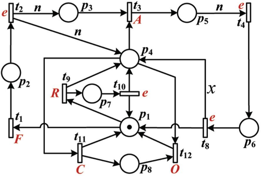
Figure 8 shows the synchronized Petri net model of supervisors based on Algorithm 2, where place is the input/output interface. At initial states, only has a token (it represents that this ES is working normally). If a fault is detected, an event F is triggered, and a token is added to . If fires, n tokens (“request” messages) are added to and , respectively, and n event sequences are generated, where the n tokens represent that this ES has n solutions , and the n event sequences are . After the n tokens are added to , they will be distributed to the n solutions with . If receives a token that is transmitted from a solution, an external event, that is, A, R, C, or O, will occur, where A, R, C, or O represents that will receive an “acknowledgment,” a “request,” or a “close” or an “open” message (opening electric switches). Especially, the firing of represents that an optimal solution group is computed from n solutions. Variable x represents the solution number in an optimal solution group. If has a token, it represents that the electric switch is closed.
The synchronized Petri net model of supervisors based on Algorithm 2.
Example
According to Figures 4(a) and 5, ES has two solutions, that is, and . The electric switch between ESs and is controlled by place , and the electric switch between ES and ES is controlled by place . ESs , , and are supervised by supervisors , , and , respectively. Let , , and , where represents the kilowatt. Then, an optimal solution group of is . Figure 9 shows the combined structure of , , , and their DCS, denoted as , where ESs , , and are monitored and controlled by supervisors , , and , respectively, represents that has two solutions, and represents that the optimal solution group of contains two items.
The combined structure based on , , , and their DCS.
If a fault occurs in the input lines of (this means that cannot fire to add tokens to ) during peak periods, the fault can be detected by the current sensor of . Let be the initial marking, we have , , , , , , , , , , and . If there exists a marking such that and , this means that the fault can be restored, and two electric switches and are closed.
The current sensor of supervisor sends an event F to its fault controller. This means that has a token. If event F occurs, fires and will fire continually. The transition sequence is . Therefore, two tokens are added to and two event sequences and are generated by the fault controller of supervisor with Algorithm 1 as follows
After two tokens are transmitted to supervisors and according to event sequences and , this means that two “request” messages are sent to the two supervisors. The transition sequence is . If forwards the token to and an event R that is generated from occurs, transitions and fire orderly. The transition sequence is . If fires, a token is added to , and an event sequence is generated by the fault controller of supervisor with Algorithm 1 as follows
If forwards a token to , this means that it returns an “acknowledgment” message to supervisor with the value according to . Therefore, has a token that will be forwarded to . If an event A that is generated from occurs, will fire, and a token will be added to (this means that records the value ). The transition sequence is . Similarly, returns to according to an event sequence that is generated by the fault controller of supervisor with Algorithm 1 as follows
The transition sequence is . Therefore, has two tokens ( and ). Since , transition fires (an optimal solution group, i.e., , is computed according to and ) and a token is added to . We have . If fires, two tokens are added to and two event sequences and are generated by the fault controller of supervisor with Algorithm 1. The transition sequence is . Place forwards a token to and another token to (this means that two “close” messages are sent from to and , respectively). If the events contained in and occur orderly, the two tokens will be distributed to and . The related transition sequence is .
The tokens contained in and will be forwarded into and , respectively. If event C that is generated from occurs, transition will fire and a token will be added to electric switch . Similarly, transition will fire and a token will be added to electric switch if event C occurs. The marking is obtained such that and . The transition sequence is . Then, solution can supply electric power to and solution can supply electric power to . Finally, has electric power for its output since , and the fault is restored. According to the initial marking , marking can be verified using state equation
where and are the input and output matrixes, is the Parikh vector of transition sequence , and .
Discussion
In a DCS , the number of communication lines (NCLs) is optimized by simplifying its structure. Let
be supervisors such that they have a same upper supervisor , where ;
be supervisors such that they have a same upper supervisor , where ;
For all and , , and .
We have and , where and . Therefore, the NCL between and is x, denoted as . Similarly, we have for and . If , the NCL between and is . Otherwise, such that and . We have and . The NCL between (respectively, ) and (respectively, ) is (respectively, ). If , the NCL between and is
Otherwise, we have . The NCL between and is . The NCL between and is
In the two methods presented by Zhabelova and Vyatkin3 and Vyatkin et al.,12 a remotely operated switch (ROS) sends a message to a middle ROS that will deliver this message to an FB to ask for power supply. We have for the ROS and FB. In the method proposed by Momoh,7 a faulty load agent directly contacts a bus agent to ask for power supply if it obtains an authorization. We have for the faulty load agent and bus agent. If the communication between and is considered with the existing three methods, we have for Zhabelova and Vyatkin3 and Vyatkin et al.12 and for Momoh.7 If , comparing the DCSs presented in the three methods and our proposed DCS. The advantage of our proposed DCS is shown in Figure 10 with the increase of x.
The comparison of DCSs.
In the example of previous section, we assume that , , and during off-peak periods. Then, and . One of and can supply electric power to since and . In our proposed method, the solution groups of are , , and . The filtered solution groups of are and . The optimal solution group of is . Therefore, the fault detected by the supervisor of can be restored by . The utilized available loads are . Another solution can be used to restore other faults that occur in other ESs (their output loads may be greater than that of ).
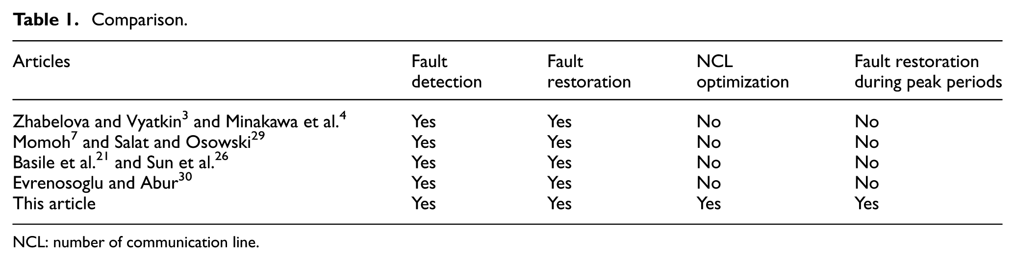
Let , , and during peak periods. The fault detected by the supervisor of cannot be restored since and . The utilized available loads are . In our proposed method, the fault can be restored by an optimal solution group presented in the example of previous section. The utilized available loads are . Therefore, the utilization of available loads is improved in traditional PTSs by computing the optimal solution group for each fault. Table 1 shows the comparison of the proposed DCS and other existing DCSs. It is clear that the proposed method is superior by comparing with other existing methods in terms of fault restoration during peak periods.
In this article, the structure of traditional PTSs is simplified by dividing ESs into three layers. The formal description of traditional PTSs is introduced. A methodology is proposed to design DCSs for the simplified traditional PTSs. The faults that occur in the input lines of ESs can be detected by supervisors. Compared with existing studies, the advantage of the proposed method is that the optimal solution groups can be computed to restore faults by executing the proposed coordination protocol during peak and off-peak periods. The proposed coordination protocol can improve the utilization of available loads in traditional PTSs. Moreover, the NCLs are optimized in the designed DCSs. The correctness of fault restoration is verified using the mathematical methods of synchronized Petri nets.
There are some disadvantages for the proposed method. The designed DCSs can detect and restore power transmission faults but cannot diagnose faults. Each ES should be preconnected with other ESs for its fault restoration. It may increase the implementation complexity of the proposed method. In addition, the proposed method is lack of appropriate simulation tools. The limitation of the proposed method is that each ES should have at least one solution group to ensure the fault restoration if a fault is detected by its supervisor. In future work, we plan to deal with these problems. A fault diagnosis method should be proposed to promote failure equipment repair. The number of preconnected lines between any ES and its solutions should be optimized. The structures of traditional PTSs and the proposed DCSs will be simulated using the FBs of IEC 61499. Furthermore, the proposed methods will be implemented in programmable logic controllers (PLCs) by converting the controlled Petri net models into ladder logic diagrams that are the most popular programming language for programming PLCs. The purpose is to enhance the integrity of the proposed methodology from the conceptual design to real implementation.
Footnotes
Handling Editor: Tatsushi Nishi
Declaration of conflicting interests
The author(s) declared no potential conflicts of interest with respect to the research, authorship, and/or publication of this article.
Funding
The author(s) disclosed receipt of the following financial support for the research, authorship, and/or publication of this article: This work was supported in part by the Foundation of Sichuan Educational Committee under grant no.16ZA0158, the “Chun hui” Research Funds for Educational Department of China under grant nos. Z2016151 and Z2015100, the Key Scientific Research Fund of Xihua University under grant no. Z1512625, the Open Research Subject of Key Laboratory (Research Base) of Network Intelligent Information Processing under grant no. szjj2016-045, the Scientific Research Funds Project of Science and Technology Department of Sichuan Province under grant no. 2016JY244, the Fundamental Research Funds for Science and Technology Department of Sichuan Province under grant no. 2013JY0089, and the Fundamental Research Funds for Educational Department of Sichuan Province under grant no. 08ZA029.
References
1.
JungKHKimHRhoD.Determination of the installation site and optimal capacity of the battery energy storage system for load leveling. IEEE T Energy Conver1996; 11: 162–167.
2.
BhargavaBDishawG.Application of an energy source power system stabilizer on the 10 MW battery energy storage system at Chino substation. IEEE T Power Syst1998; 13: 145–151.
3.
ZhabelovaGVyatkinV.Multiagent smart grid automation architecture based on IEC 61850/61499 intelligent logical nodes. IEEE T Ind Electron2012; 59: 2351–2362.
4.
MinakawaTLchikawaYKunugiMet al. Development and implementation of a power system fault diagnosis expert system. IEEE T Power Syst1995; 10: 932–940.
5.
ChienCFChenSLLinYS.Using Bayesian network for fault location on distribution feeder. IEEE T Power Deliver2002; 17: 785–793.
6.
MaDYLiangYCZhaoXSet al. Multi-BP expert system for fault diagnosis of powersystem. Eng Appl Artif Intel2013; 26: 937–944.
7.
MomohJA. Navy ship power system restoration using multi-agent approach. In: Proceedings of the IEEE power engineering society general meeting, Montreal, Canada, 18–22 June 2006, pp.14–18. New York: IEEE
8.
XuYLLiuWX.Novel multiagent based load restoration algorithm for microgrids. IEEE T Smart Grid2011; 2: 152–161.
9.
TongXYWangXRWangRet al. The study of a regional decentralized peer-to-peer negotiation-based wide-area backup protection multi-agent system. IEEE T Smart Grid2013; 4: 1197–1206.
10.
VyatkinV.IEC 61499 as enabler of distributed and intelligent automation: state-of-the-art review. IEEE T Ind Inform2011; 7: 768–781.
11.
HigginsNVyatkinVNairNCet al. Distributed power system automation with IEC 61850, IEC 61499, and intelligent control. IEEE T Syst Man Cy C2011; 41: 81–92.
12.
VyatkinVZhabelovaGHigginsNet al. Towards intelligent smart grid devices with IEC 61850 interoperability and IEC 61499 open control architecture. In: Proceedings of the IEEE PES transmission and distribution conference and exposition, New Orleans, LA, 19–22 April 2010, pp.1–8. New York: IEEE.
13.
ChenYFLiZWBarkaouiKet al. On the enforcement of a class of nonlinear constraints on Petri nets. Automatica2015; 55: 116–124.
14.
AntonioRTElviaRBIsraelRRet al. Online fault diagnosis of discrete event systems. A Petri net-based approach. IEEE T Autom Sci Eng2007; 4: 31–39.
15.
LiraDNGarciaJIJunqueirayFet al. Fault detection in flexible assembly systems using Petri net. IEEE Lat Am T2008; 6: 572–578.
16.
DimitriLEdouardL.Stochastic Petri net identification for the fault detection and isolation of discrete event systems. IEEE T Syst Man Cy A2011; 41: 213–225.
17.
MahuleaCSeatzuCCabasinoMPet al. Fault diagnosis of discrete–event systems using continuous Petri nets. IEEE T Syst Man Cy A2012; 42: 970–984.
18.
RenganathanKBhaskarV.Modeling, analysis and performance evaluation for fault diagnosis and fault tolerant control in bottle-filling plant modeled using hybrid Petri nets. Appl Math Model2013; 37: 4842–4859.
19.
LefebvreD.On-line fault diagnosis with partially observed Petri nets. IEEE T Automat Contr2014; 59: 1919–1924.
20.
CabralFGMoreiraMVDieneOet al. A Petri net diagnoser for discrete event systems modeled by finite state automata. IEEE T Automat Contr2014; 60: 59–71.
21.
BasileFCabasinoMPSeatzuC.State estimation and fault diagnosis of labeled time Petri net systems with unobservable transitions. IEEE T Automat Contr2015; 60: 997–1009.
22.
WangXMahuleaCSilvaM.Diagnosis of time Petri nets using fault diagnosis graph. IEEE T Automat Contr2015; 60: 2321–2335.
23.
GhainaniATZinAAMIsmailNAM. Fuzzy timing Petri net for fault diagnosis in power system. Math Probl Eng2012; 2012: 1–12.
24.
ShiYSSunWSLiCL.Fault diagnosis of micro-grid based on advanced Petri net. Appl Mech Mater2012; 130: 3015–3018.
25.
ZhangYZhangYWenFet al. A fuzzy Petri net based approach for fault diagnosis in power systems considering temporal constraints. Int J Elec Power2016; 78: 215–224.
26.
SunJQinSYSongYH.Fault diagnosis of electric power systems based on fuzzy Petri nets. IEEE T Power Syst2004; 19: 2053–2059.
27.
WangLChenQGaoZJet al. Knowledge representation and general Petri net models for power grid fault diagnosis. IET Gener Transm Distrib2015; 9: 866–873.
28.
CalderaroVHadjicostisCNPiccoloAet al. Failure identification in smart grids based on Petri net modeling. IEEE T Ind Electron2011; 58: 4613–4623.
29.
SalatROsowskiS.Accurate fault location in the power transmission line using support vector machine approach. IEEE T Power Syst2004; 19: 979–986.
30.
EvrenosogluCYAburA.Travelling wave based fault location for teed circuits. IEEE T Power Deliver2005; 20: 1115–1121.
31.
MurataT.Petri nets: properties, analysis and applications. P IEEE1989; 77: 541–580.
32.
DavidRAliaH.Discrete, continuous, and hybrid Petri nets. Heidelberg: Springer, 2005.
33.
UzamMJonesAH.Discrete event control system design using automation Petri nets and their ladder diagram implementation. Int J Adv Manuf Tech1998; 14716–728.