
Abstract
The purpose of this article is to propose an upshift control strategy for off-highway vehicles equipped with a new kind of drivetrain architecture, which is called multi-clutch transmission, by means of analysis, modeling, and experiments. First, the structure and working principle of the multi-clutch transmission is investigated in detail. Then, to achieve a smooth 3–4 upshift process with two on-coming clutches and two off-going clutches working together, the method of power flow investigation is introduced. From the analysis results, the optimal relationship between clutches is presented to avoid engine flare and clutch tie-up. Additionally, the engagement sequence of on-coming clutches is also optimized to reduce the shift time and friction work. Then, with the proposed control strategy, a dynamic model for the integrated off-highway vehicle is developed using MATLAB/Simulink. From the variations in torque and speed output obtained from the simulation results, the vehicle equipped with multi-clutch transmission possesses good longitudinal dynamic performance, with acceptable friction work generated from two slipping clutches during the entire upshift process. Finally, to assess the shift quality, the test bench has been conducted. The obtained experimental data show a good agreement with the simulation results and the effectiveness of the control strategy is validated.
Introduction
Off-highway vehicles (OHVs) are those not designed for the road service and capable of cross-country travel on land, snow, ice, hill, marsh, or other natural terrain. Apparently, the introduction of the OHVs has brought a revolution in mobility and convenience to the modern life, but at the same time, resulted in environmental and global energy issues. 1 In response to these issues, automotive manufacturers shift their attention toward more advanced and energy-efficient automotive technologies, such as high efficiency engine, hybridization, weight reduction. Among them, the power transmission technologies can provide the most prominent improvements regarding the fuel efficiency and emission, 2 in particular for the heavy-duty OHVs, including the agricultural machinery, industrial machinery, and tracked vehicles. For these kinds of OHVs, electric drive, hydraulic drive, and mechanical drive have been widely used.
As one of the most efficient solutions to reduce the fuel consumption, the hybrid electric vehicles have been investigated by multiple researchers.3–7 However, the criticisms of the electric system, which weigh against its flexibility and ease of control, are its weight, cost, and use of brushes and commutator. Besides, OHVs usually operate in dirty environments with wheels sometimes submerged in water. Thus, the application of the electric drive is limited to a certain extent. As for the hydraulic transmission, although considerable research has been done to improve the system efficiency of the hydraulic OHVs,8–11 the rate of energy utilization is still unsatisfactory. When it comes to the mechanical drive, the manual transmission (MT) and planetary-type automatic transmission (AT) also have extensive application in OHVs. MT has the highest efficiency due to their inherently low parasitic losses (96%). However, this kind of transmission requires the drivers to actuate the clutch and change the gear manually, and most drivers find such tasks troublesome. 12 For AT, significant amount of energy is wasted due to the slipping nature of the torque converter; thus, the efficiency ranges from 86% to 94%. Fortunately, dual clutch transmission (DCT), which use two clutches and synchronizers to accomplish the launch and shift processes, is developed to overcome the shortcomings of other types of transmissions.13,14 Nevertheless, it is still a serious challenge for DCT to be applied on the OHVs due to the severe environments and the heavy shock load. Not only that, the safety and reliability of the precision components is doubtable, in particular for the synchronizers, which are frequently used during DCT shift processes.
Throughout the above three kinds of driving methods applied on the OHVs, considering the cost, fuel efficiency, working conditions of the OHVs, and the advantages of the current various transmissions, a new type of transmission, which is named as multi-clutch transmission (MCT), is developed by the authors independently. When MCT is applied on the OHVs, several advantages over other driving methods can be obtained. First, as MCT shares similar structure with DCT, a high system efficiency can be guaranteed. In addition, MCT is less costly to manufacture in comparison with AT since it employs the conventional MT architecture. Second, in MCT, the shift and launch processes are also accomplished with the slipping clutches. Thus, the technologies developed for DCT can be utilized by MCT directly.15–17 Third, instead of using the synchronizers, the shift components in MCT are clutches, which are the same with those in AT. Hence, MCT can not only overcome the shortcomings of the current transmissions, but achieve high safety and reliability. However, although MCT seems to have all these advantages, further enhancements are still required to enable it to possess the same or higher level of vehicle performances regarding comfort, ride and drivability, compared with conventional transmissions. Thus, in this article, a control strategy is proposed for the MCT shift process with four clutches working together in particular.
This article is organized as follows. Section “MCT powertrain model development” introduces the structure and working principle of the designed MCT. Also, a powertrain model is presented. Section “Coordination between clutches for MCT upshift” focuses on the relationship optimization between four clutches based on the power flow analysis. Section “Upshift control strategy for MCT” proposes an upshift control strategy for the MCT upshift. Section “Simulation and experiment” presents the simulation and experimental results, including the variations of the torque, speed, jerk level, and friction work during the upshift process. Finally, the conclusions from this work are outlined.
MCT powertrain model development
MCT structure and working principle
The structure of the developed MCT, consisted of six wet clutches and three shafts, is shown schematically in Figure 1. Obviously, the gearshifts are completed with only slipping clutches and the pre-engagement process of the synchronizers does not exist in MCT. Main parameters of this new-style transmission, including the clutch reserve coefficient of CH and C1, are shown in Table 1, which are used for analysis and simulations.

Driveline model of the multi-clutch transmission system.
Main parameters.

Kinematically, a MCT can be considered as a combination of two DCTs without synchronizers. By controlling the clutches CL, CH, CR, and C1–C3, various gear ratios can be achieved to regulate the operating range of the engine. When in a particular gear, the respective clutches are engaged and the power from the engine is transmitted from the input shaft, through the middle shaft, finally to the output shaft. To change a gear, the off-going clutch is released and the on-coming clutch is engaged according to the schedule listed in Table 2, in which “•” represents that the corresponding clutch is engaged for the specific gear. Generally, the cooperation between two clutches is already enough to accomplish most of the gearshifts, which is similar to the shift process in DCT.18–22 However, in MCT, four clutches including CL, CH, C1, and C3 are involved during the shift process between third and fourth. Thus, it is necessary to propose a special control strategy for this gearshift process. Because the downshift process is the reverse process of the upshift process, only the upshift control strategy is investigated in this article. However, the downshift control strategy can be proposed in a similar way.
Clutch schedule for each gear in MCT.

•: specific clutch engaged for corresponding gear.
Powertrain model and upshift process description
Component model
A precise analytical model, which can describe the dynamic process effectively during the system operation, is of great importance to the success of control. The MCT vehicle consists of complicated components such as the engine, clutches, and vehicle load. The specific models are described as follows.
For OHVs, the diesel engine is usually adopted as the power source to acquire an excellent vehicle power performance. For simplicity, the engine is modeled as a mean value torque generator. The engine output torque, determined by engine speed and throttle opening, is described as an engine map. As shown in Figure 2, the throttle opening varies from 5% to 100% and the engine speed ranges from 800 to 2750 r/min


Engine output torque model.
The clutches in MCT are the essential gear changing elements in addition to the original purpose of transmitting the power from the engine to the drivetrain. The friction torque transferred by clutches can be calculated according to the geometry and friction characteristics of the clutch, 23 which is shown in equation (2)
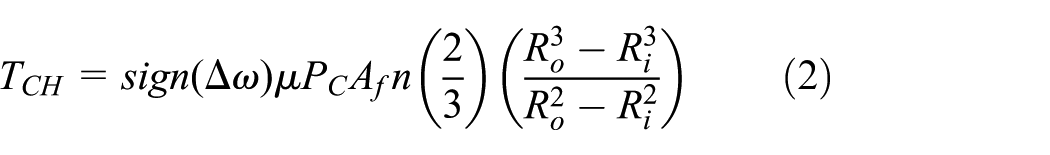
The friction coefficient μ, in equation (2), has a strong relationship with the relative angular speed between two plates of the clutch. 21 Based on the experimental data, equation (3) describes the variations of the friction coefficient 23

The driving resistance of the OHVs, which accounts for the road slope resistance, the rolling resistance, and aerodynamic resistance, is formulated in equation (4)

System model for MCT upshift process
Different sets of dynamic equations are required to describe the system dynamics due to the change of the clutch status during the MCT upshift process. When the OHVs operate in a particular gear, MCT provides a mechanical link between the engine and the final drive. During the upshift process, the powertrain system is in a dynamic shift state. Different stages of the specific 3–4 gearshift process are shown in Figure 3. And, according to the dynamic balance relationship, the equations for MCT can be derived as follows.
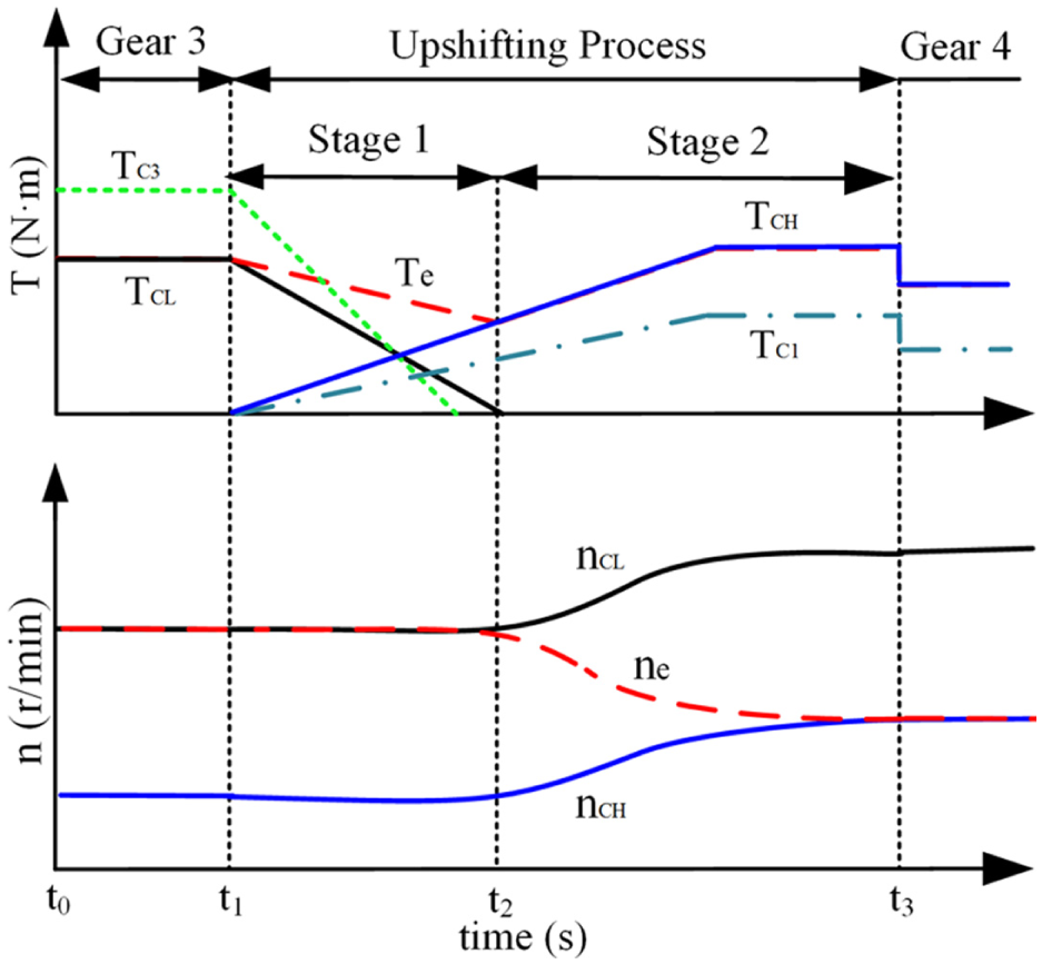
Different stages of the MCT upshift process.
When the MCT operates in third gear (t0 – t1), CL and C3 are engaged, while other clutches are open


When MCT operates in this gear, the system torque transferred by CL and C3 can be described by the following equations


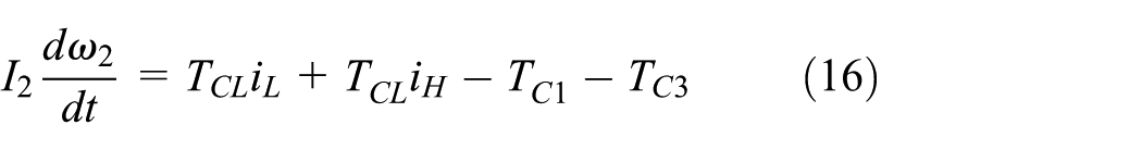
When MCT receives the shift signal from the transmission control unit, the upshift process starts immediately (t1 – t3). The pressures applied on the off-going clutches (CL and C3) are released gradually, resulting in the decrease of the torque capacity of clutches. While the pressures on the on-coming clutches (CH and C1) increase. Then, the power from the engine is redistributed between four clutches gradually. After the releasing pressure reduces to 0, CH and C1 work together to transfer the engine power. Thus, the MCT upshift process can be divided into two stages and two sets of equations are required. During the first stage (t1 – t2), as the slippage of CH and C1, equations (6)–(8) should be changed into equations (15)–(17), and the rest of equations are the same as those in the third gear


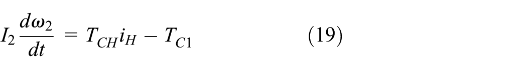
As for the stage two (t2 – t3), the engine torque is transmitted by CH and C1 and the MCT status is expressed as follows


When the relative angular velocity between driving and driven plates of both CH and C1 reduces to 0, MCT shifts to the fourth gear (after t3). Then, the pressures applied on two on-coming clutches increase rapidly to the line pressure and the upshift process ends. Equations (21)–(23) describe the MCT status
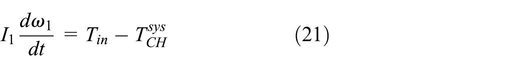


Similar to the status when MCT runs in the third gear, the torque transferred by CH and C1 is shown as follows

Coordination between clutches for MCT upshift
During the upshift process, an inappropriate relationship between clutches always results in power circulation or interruption. To avoid the energy loss and improve the shift quality, this kind of relationship should be optimized.
Relationship optimization between four clutches
To obtain an optimal cooperation mode and achieve the highest system efficiency, the method of power flow analysis is introduced. As shown in Figure 4, a simplified MCT system is used to show the power flow path during the first stage.

Power flow path during the first stage.
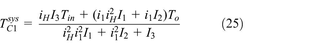
From the input engine power to the MCT output power, equations (26)–(33) describe the power flow condition


Define


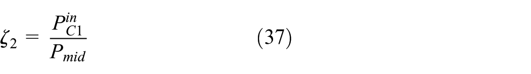
Then, the MCT system efficiency during the first stage can be deduced from equations (26)–(37)
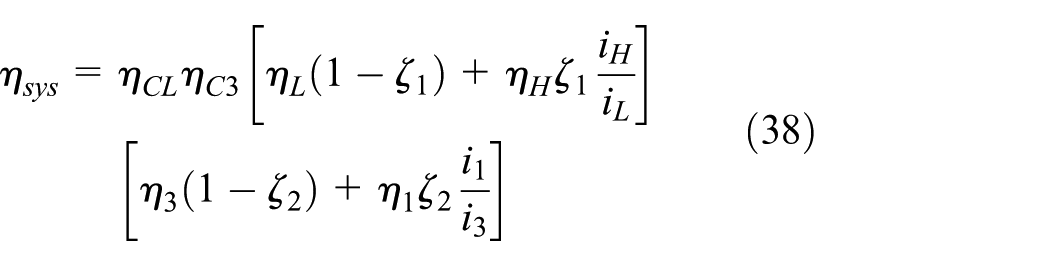
Most parameters in equation (38), including iH, iL, i1, i3, ηL, ηH, η1, and η3, are constant. As for ζ1 and ζ2, these two variables always vary from 0 to 1 with the decrease of the pressures applied on CL and C3. Thus, the MCT system efficiency mainly has a strong relationship with ηCL and ηC3. According to equations (34) and (35), different CL and C3 statuses during the first stage are investigated in the following.
As shown in Figure 5, the power circulation generates when

Different status of CL and C3 during the first stage.
According to the above analysis, the optimized relationship between four clutches for MCT to upshift is obtained. To realize this optimal status, the relationship between TCL, TCH, TC1, and TC3 should be optimized to enable the off-going clutches to transfer the system torque. Thus, according to equations (15)–(17), the optimal relationships are presented as follows


where
Engagement sequence optimization for on-coming clutches
To obtain an optimal engagement sequence for CH and C1, the MCT components are considered as rigid for simplicity, which has no effect on analysis results. As shown in Figure 1, the series connection between CH and C1 in the powertrain system indicates that the friction work generated during the upshift process cannot be shared by two clutches. Thus, engaging one clutch quickly and another one slowly is a better way for MCT to accomplish the engagement process with fewer friction work. Consequently, two different methods to engage CH and C1 has been proposed in the following part, which lead to different effects on the shift quality.
The first method is to engage CH and then C1. During the CH engagement process, the amount of the generated friction work is negligible, due to the short time and small friction torque. And, the friction work generated by C1 can be described as
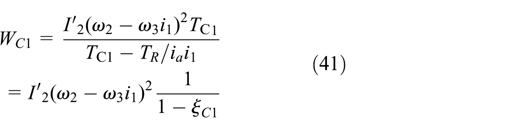
where
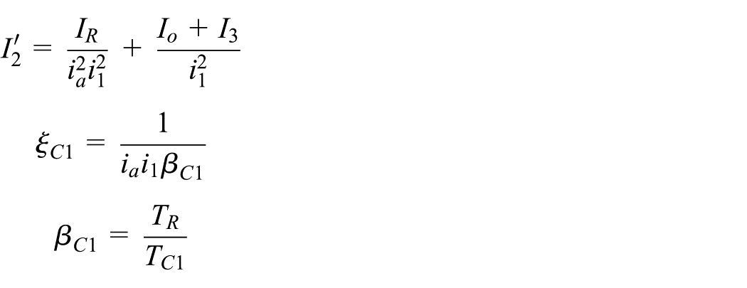
The second method has the opposite engagement sequence. After C1 is engaged, CH starts to work and the generated friction work can be deduced in a similar way

where
According to equations (41) and (42), the amount of the friction work has a strong relationship with
After CL and C3 are released and C1 is engaged, the first stage comes to the end and the second stage starts. As mentioned in section “System model for MCT upshift process,” two clutches (C1 and CH) work together to transfer the engine torque during this stage, however, with only CH slipping. Thus, this engagement process is much similar to the inertia phase in the DCT and AT.24–27 As much work has been done to ensure a smooth process by balancing the friction work and shift intensity, the control method for the CH engagement during the second stage is not involved in this article.
Upshift control strategy for MCT
A novel control strategy is developed for MCT base on the investigation of the structure, establishment of the dynamic model of the upshift process and, in particular, the relationship optimization between clutches. From the shift decision-making process, to the combined motions between four clutches, then the control of the CH engagement, the entire upshift process can be considered as a logical combination of a series of interdependent events. And, after MCT receives the shift decision, the upshift process starts immediately.
First, the pressures applied on the off-going clutches should be reduced to the critical value that the torque capacity of CL and C3 equals to the system torque quickly. Meanwhile, the pressures applied on the on-coming clutches (CH and C1) ramp up to eliminate the clutch free travel. This stage is the preparation for the shift process and the off-going and on-coming clutches have little effect on the shift quality.
When the first stage starts, the torque from the engine is transferred from the off-going clutches to the on-coming clutches. Usually, the charging pressure is decided according to the driver’s intentions 28 or calculated according to the optimal control theory. 29 However, no matter how the charging pressure varies, the releasing pressure profiles applied on the CL and C3 can be obtained based on equations (39) and (40). With the increase of the charging pressures, the system torque transferred by off-going clutches decreases. And due to the optimized relationship between four clutches, the relative angular velocity between the input and output sides of the two off-coming clutches maintains 0. Meanwhile, the engine power redistributes between them four without power interruption and power circulation. Until the releasing pressures applied on CL and C3 become 0, the first stage ends and the second stage starts.
During the second stage of the upshift process, only CH slips to achieve the synchronization process. Once the relative velocity between the two disks of CH becomes 0, the entire upshift process comes to the end and, for the sake of convenience, the charging pressures applied on CH and C1 increase to the line pressure together.
According to the above proposed control strategy, MCT can obtain the highest system efficiency during the first stage which means the least friction work. In addition, after the quick engagement of C1, the shift quality can be guaranteed with the controlled CH. The architecture of the control strategy is shown in Figure 6.

Architecture of the control strategy for MCT upshift.
Simulation and experiment
The simulation model of the MCT is established on the MATLAB/Simulink platform according to the dynamic process and the proposed control strategy. Meanwhile, to validate the correctness of the model and the effectiveness of the control strategy, the experiments on the test bench equipped with MCT are conducted.
Simulation results and analysis
The simulation model is constructed on the basis of the dynamic equations. Main parameters of the MCT have been illustrated in Table 1. The simulation is carried out under 40% throttle opening.
With the proposed control strategy, the numerical results of the pressure profiles applied on the four clutches are shown in Figure 7. Considering the experimental difficulties, the slope charging pressure is adopted to apply on the on-coming clutches. 2 To ensure C1 is engaged first, PC1 increases faster than PCH. In the beginning of the upshift, the pressures applied on the CL and C3 are reduced to the critical value of where two clutches start to slip. Then, with the optimized relationship, the engine torque transfer process is achieved by the mutual cooperation between four clutches. After two on-coming clutches are engaged successively, two charging pressure profiles are increased to the line pressure sharply at the same time.

Pressure profiles applied on four clutches.
Dynamic responses of the engine and MCT are shown in Figures 8–13. Obviously, the torque curves in Figure 8 have little fluctuation during the first stage due to the excellent match of four clutches as shown in Figure 9, which means a smooth torque transfer between clutches is achieved. After that, the upshift process is alternated to the second stage. Without the adjustment of the engine throttle, the friction torque transferred by CH not only overcomes the driving resistance, but accelerates the vehicle to engage CH. Thus, during this stage, TCH has an apparent increase from 300 to 708 N m. However, after CH is engaged, it begins to transfer the system torque and just overcomes the driving resistance. Then, TCH declines to 307 N m. During the first stage, clutch C3 is released first (0.61 s) and then CL is released (0.68 s).
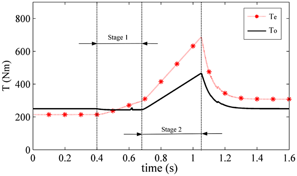
MCT input and output torque.

Torque transferred by four clutches.
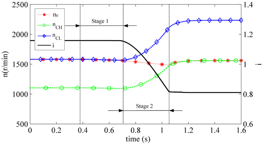
Velocity speeds of engine, CH, and CL and variation of gear ratio of MCT system.
Velocity speeds of middle shaft, C1, and C3 and variation of gear ratio on the middle shaft.
Jerk level during the MCT upshift process.
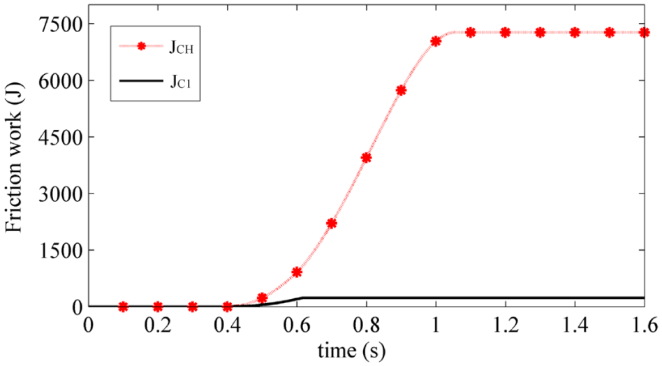
Friction work generated during the MCT upshift process.
Figure 10 indicates the variations of the velocity speed of the engine, CL and CH. During the first stage, CL is always under the engaged status when it transmits the system torque. Thus, no friction work generates, which is the same as described in the control strategy. When the second stage comes, both the decreased engine speed and the increased clutch speed are conducive to the engagement of on-coming clutch CH. In terms of the speed curves shown in Figure 11, it can be seen that the middle shaft is synchronized with C3 before 0.6 s. However, to reduce the friction work, this shaft shifts to engage with C1 quickly according to the proposed control strategy. And, due to the small mass moment of inertia of the middle shaft compared with that of the vehicle body, the shift process is only 0.02 s. Thus, the gear ratio on the middle shaft changes from 0.974 to 0.925 suddenly. Nevertheless, as shown in Figure 10, during the entire upshift process, the gear ratio of the MCT varies from 1.17 to 0.81 smoothly due to the appropriate control strategy.
The jerk intensity is shown in Figure 12. During the first stage, the engine torque is transferred from the off-going clutches to the on-coming clutches smoothly with the optimized relationship. Thus, the jerk value is almost 0. As for the second stage, the friction torque transferred by CH increases to accelerate the vehicle. Then, the jerk value changes to 1.1 m/s3. After CH is engaged, TCH returns to a steady value (307 N m), leading to a drastic change in the jerk level (6.8 m/s3). However, during the entire upshift process, the absolute value of the jerk level is still less than 10 m/s3, which satisfies standard requirements. When it comes to the friction work generated during the upshift process shown in Figure 13, the amount of CH and C1 is 7276 and 231 J, respectively, which is acceptable.
Experiment results and analysis
To evaluate the shift control strategy proposed for the MCT, a test bench is conducted. Due to the limitation of experiment equipment, a 205 kW motor is adopted to drive the MCT system. In section “Component model,” the engine model does not take the engine transients, throttle response delay, and fuel loss caused by excessive throttle opening into account; thus, the motor is sufficient and qualified to simulate the engine performance curve. The shift actuators are controlled through the hydraulic valves. Two torque-speed sensors are mounted with the input and output shafts of MCT to measure the speed and torque, respectively. The fly-wheel inertia is used to simulate the vehicle mass. And a hydraulic pump equipped with an overflow valve is used to apply the load. Figure 14 shows the bench scheme.
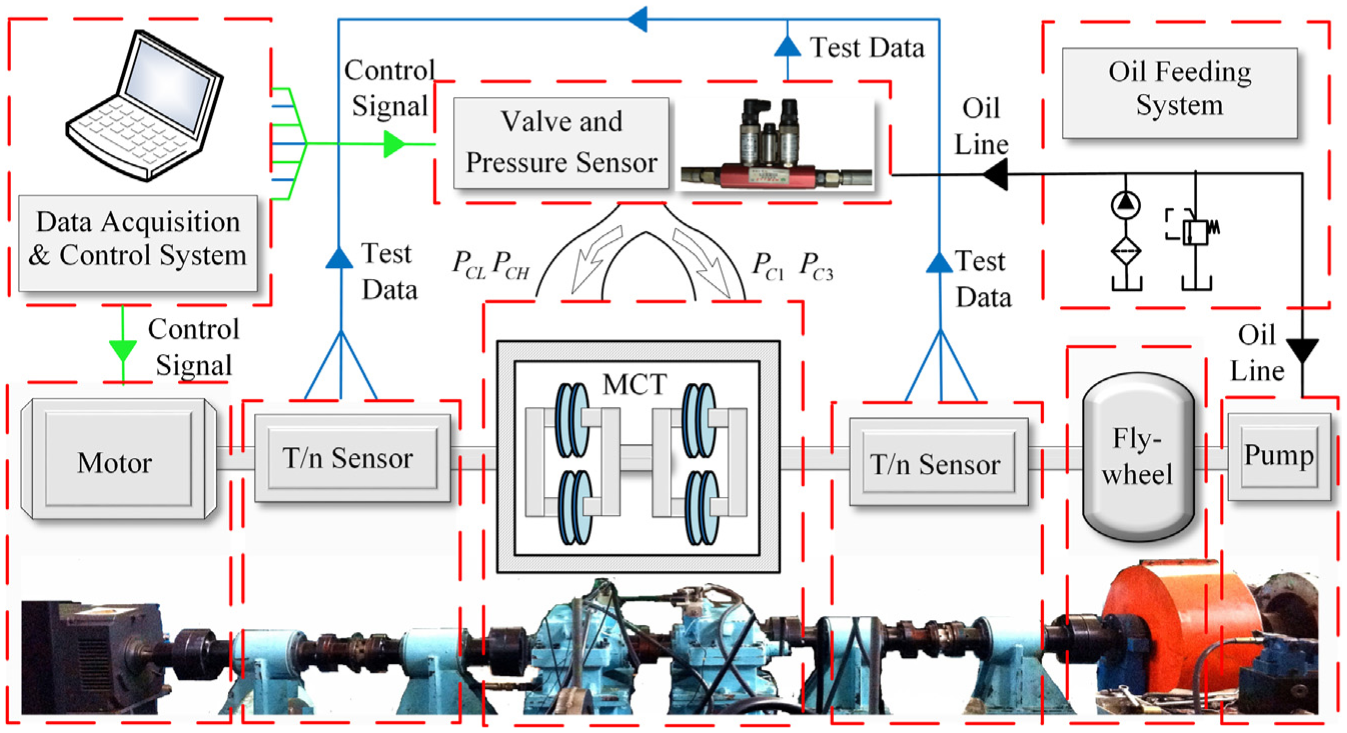
The test bench.
In Figure 15, the obtained effective pressure profiles applied on four clutches are demonstrated. Obviously, the test data have a good agreement with the simulation results shown in Figure 7.

Pressure profiles applied on four clutches.
Due to the technical difficulty of installing torque measuring sensors within the four clutch packs, the torque transferred by clutches cannot be compared against the simulation results. Nevertheless, the input and output torque curves shown in Figure 16 are still valid to reflect the torque transferred by four clutches and analyze the dynamic upshift process. As shown in Figure 16, the MCT system experiences a smooth torque transfer process between four clutches without power interruption and power circulation, which is the same as the simulation results shown in Figure 8 during the first stage. As for the second stage, both input and output torques increase to accelerate the system. However, after the upshift process, the torque curves have a smoother changing trend compared with the simulation results shown in Figure 8. This is because the simulation model ignores the stiffness and damping of the MCT system. In addition, the existence of the resistance factors in experiments also has a certain influence.

MCT input and output torque.
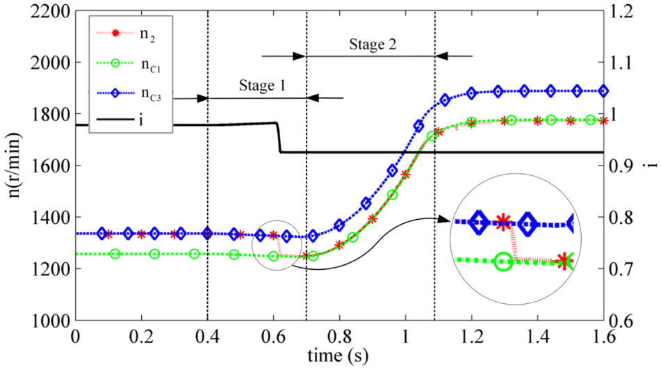
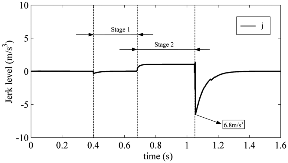
In terms of the speed curves, the variation of the speed of the middle shaft, which is inside the MCT, cannot be measured neither. Nevertheless, with MCT input and output speed curves, the operation conditions inside MCT can be reflected indirectly. As shown in Figure 17, the test data are highly agreeable to the simulation results as shown in Figure 10. During the first stage, the speed curves almost have no change and CL is under the engaged status, due to the coordinated relationship between four clutches. When the second stage comes, CH slips to engage with the input shaft. After the relative speed between the driving and driven plates of CH becomes 0, the upshift process comes to the end. It can be seen that the speed curves vary steadily and the gear ratio of MCT changes from 1.17 to 0.81 smoothly during the entire process. The comfortable upshift process can be evaluated by the jerk intensity, as shown in Figure 18, with 6.3 m/s3.

Velocity speeds of engine, CH, and CL and variation of gear ratio of MCT system.
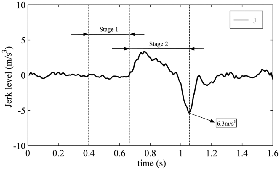
Jerk level during the MCT upshift process.
Thus, throughout the experimental data, MCT is validated to be capable of achieving a high-quality upshift process with four clutches working together. And, by the comparison between the simulation and experimental results, the correctness of the proposed dynamic model is verified.
Conclusion
This article aims at presenting an upshift control strategy for OHVs equipped with the self-designed MCT. Based on the power flow analysis, the optimal cooperation control between four clutches, including two on-coming clutches and two off-going clutches, is developed to accomplish the specific 3–4 upshift process in MCT smoothly. Then, according to the proposed control strategy, a dynamic and mathematical model, integrating the diesel engine, MCT, and the vehicle environment, is presented for numerical simulations of transient responses of OHV during upshift process. From the obtained simulation results, the proposed control strategy can not only avoid power interruption and power circulation, but satisfy the requirements of the shift quality, in terms of jerk intensity and friction work. Finally, the proposed control strategy is implemented on the test bench. And from the agreement between simulation results and experimental data, the correctness of the simulation model and the effectiveness of the control strategy are verified. It can be anticipated that the development of fuel economy with improved shift quality can be obtained with the application of MCT on actual OHVs.
Footnotes
Appendix 1
Handling Editor: Seiichiro Katsura
Declaration of conflicting interests
The author(s) declared no potential conflicts of interest with respect to the research, authorship, and/or publication of this article.
Funding
The author(s) disclosed receipt of the following financial support for the research, authorship, and/or publication of this article: This work was supported by the National Natural Science Foundation of China (grant number 51575042).