
Abstract
The development of electric bus has been an effective method of solving the energy crisis and environmental pollution caused by automotives. Present electric buses have fixed ratio gearboxes, however, the one-speed gearboxes cannot meet the requirements of torque and driving range simultaneously. Electric buses also have substantial requirements from batteries and driving motors. A driving system consisting of driving motor and multi-speed automated manual transmission has a simple structure, is cost-effective and easy to match. Therefore, this study focuses on the dedicated automated manual transmission structure of an electric bus without using a clutch and a synchronizer. The research also proposes the shift control strategy by actively synchronising the driving motor and by clearing the control phase division and the shift quality evaluation index. This index further studies the method of determining the range of optimal speed difference, the control strategy of the driving motor and other key techniques. The index also forms a practical shift integrated control strategy. In addition, prototype vehicle testing verifies that the strategy can shorten torque interruption time. Moreover, the absolute value of shift impact is far less than the standard value of 10 m/s3. Finally, the success rate of the shift reaches 100%.
Keywords
Introduction
To solve global problems, such as energy crises and environmental pollution, several governments and auto companies have taken energy saving as the main direction of future automotive development. The electric bus has low pollution, low noise, high energy efficiency and diverse power sources. In addition, the development of the electric bus, which is the representative of various new energy vehicles, is an effective method of solving problems caused by vehicles.
Currently, electric buses are mostly equipped with fixed-ratio gearboxes; however, one-speed gearboxes cannot simultaneously meet the requirements of torque and driving range and have substantial battery and driving motor requirements. A driving motor often works in inefficient zones, thereby leading to such problems as increasing system power consumption, decreasing driving range and lack of starting power. These problems restrict the use and development of electric buses. The use of an electric driving system consisting of a driving motor and multi-speed automated manual transmission (AMT) is an effective methods of solving the current problems of electric buses, such as limited driving range and poor power performance. The shift quality of AMT directly affects riding performance and driving comfort. Therefore, a reasonable shift control strategy must be developed to ensure the shift quality of AMT.
Several studies on AMT, which is applicable to electric vehicles (EVs), have paid attention to novel structures and advanced control strategies for achieving acceptable shift performance. A study of novel two-speed I-automated manual transmission (inverse AMT) was discussed, and a shift control strategy without power fluctuation was proposed.1,2 This strategy achieved a smooth shift process without torque interruption and was verified to have good performance through simulation. A control algorithm which coordinates the accurate control of engine torque and speed and the fast control of the AMT shift actuator position was developed on a test vehicle equipped with an AMT. The algorithm was validated to allow for comfortable driving and reduction in shift transients. 3 A clutchless automated manual transmission (CLAMT), which has high efficiency, low cost and simple structure, was developed. The shift control technique of CLAMT was verified through theoretical analysis, simulation and experiment. 4 A practical method referring to CLAMT and its gear-shifting control strategy for an EV was proposed, and the method was described and validated on a designed CLAMT test rig that the key technique related to the improved scheme for the gear-shifting actuators position control. 5 Zhong et al. 6 proposed a control algorithm which is based on the dynamic analysis of every shifting stage to realise clutchless shifting control. The algorithm combines engine control with motor torque and speed control. A new system that provides another means of addressing AMT applications was introduced. The system consists of a 2-degree-of-freedom electro-magnetic actuator. The system was also combined with the newly designed control strategy. 7 Another study focused on automatic transmission which has a proportional solenoid valve that controls the pressure of the clutch. A control strategy based on the speed difference of the clutch was also designed for shift control during the inertia phase. 8 A shift control strategy without torque interruption was designed for developing the driving comfort of dual motor-driven EVs with AMT. Simulation results showed that the control strategy could effectively decrease shifting impact. Shifting without torque interruption was also realised. 9 Another shift control strategy based on target gear position was proposed. The strategy can also improve driving comfort by selecting the proper speed of the target motor. A real vehicle test validated that the strategy can shorten the gear-shifting time and enhance the smoothness of gear shifting. 10 A two-speed transmission scheme without clutch was designed, and a shifting strategy was provided to guarantee the high operation efficiency of the motor. The strategy was verified to decrease energy consumption by 6.6% and extend the driving range by 7.1%, compared with EV with a fixed ratio by the simulation results. 11 A novel shift torque compensation strategy was proposed when it is in the shift process for suppressing a ripple. Analyses and simulations are conducted to test this theory. 12 A novel motor torque control strategy was proposed for vehicles before shifting, speed control strategy before gear engaging and shift actuator control strategy for engaging. 13 Another research was conducted for the global trajectory optimisation problem, to analyse parameters for the shift quality. Objective functions and constraints were also introduced in the research. 14
In this research, the study object is an electric driving system that is based on a three-speed AMT and does not use a clutch and a synchronizer. The absence of the two main friction parts, clutch and synchroniser, simplifies the system structure and improves system life. Figure 1 provides a diagram of the electric bus transmission and control system structure.

Diagram of electric bus transmission and control system structure.
For the previously mentioned system, certain key factors which can affect the quality of gear shifting, in-depth analysis and investigation are necessary. Therefore, this study first provides an in-depth analysis of the jaw clutch engaging mechanism. The research also proposes a shift quality evaluation index on the basis of analysing the AMT shift process by actively synchronising the driving motor. Studies on factors affecting the shift success probability are conducted. In addition, the optimal range of the shift speed difference is determined.
A precise motor control strategy is developed. The shift control strategy of AMT through the active synchronisation of the driving motor is proposed. The shift quality of AMT must also be improved such that it meets the requirement of smooth shift-feel and the comfortable ride.
AMT shift process and evaluation index of shift quality
The shift process is affected not only by the shift control strategy but also by the shift actuator. The success rate of shifting is considered for determining the range of optimal shift speed difference which aims to improve the quality of gear shifting.
Configurations and work principles of shift actuator
In this study, the shift actuator of an electronically and electrically actuating system is used due to its simple structure, high control precision, fast response and easy disassembly. Figure 2 shows the actuator. This system mainly consists of two shift motors, two sets of ball screw shift mechanisms and corresponding angular displacement sensors. The two shift motors drive the ball screw shift mechanisms connected with them to complete shifts. Shift motor1 is solely responsible for shift 3-N, whereas shift motor2 is solely responsible for shift 1-N-2. The two sets of shift actuators work independently. Moreover, the selection process of traditional AMT is cancelled.

Shift actuator of electronically controlled and electrically actuating system.
Figure 3 shows the physical figure of the AMT system and partial structure of the interior of the AMT. The structure of this system is relatively simple, and the transmission is small and thus easy to install.
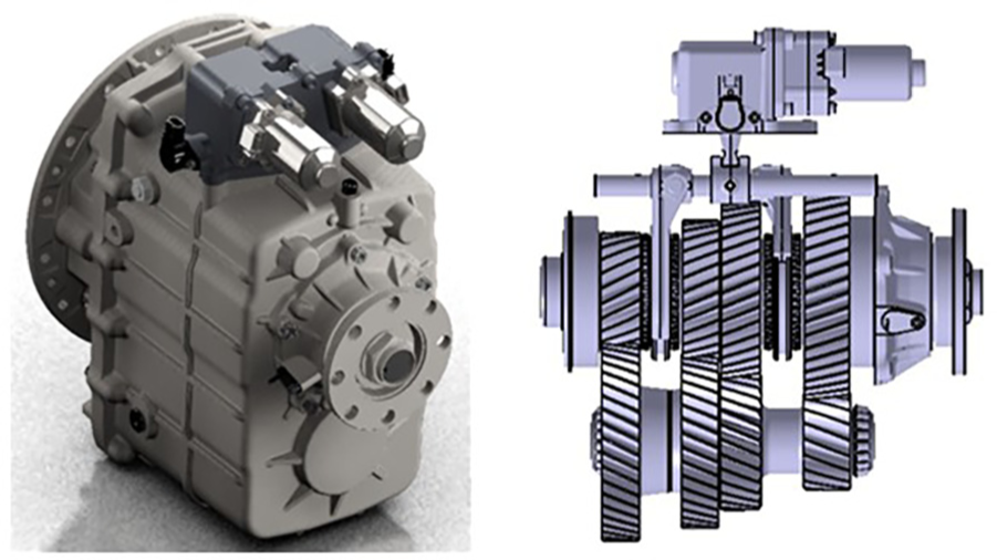
Physical figure of AMT system and partial structure of inner AMT.
Figure 4 reveals the function of the gear actuators during gear shifting. The figure also shows the internal construction of the gear actuators. In addition, the shift process between N and 3 is used to introduce the principle of a shift actuator, as shown in Figure 4(a). When AMT is required to shift, transmission control unit (TCU) controls shift motor1 to rotate and drives screw1, which is connected with motor1 shaft, to rotate. Therefore, the rotational motion of screw1 translates to the linear motion of ball1. The axial motion of ball1 drives the shift rocker to rotate around its axis. Figure 4(a) indicates that one end of the rocker makes contact with the shift fork. The rotational motion of the shift rocker can also push the axial motion of the shift fork. Therefore, the motion of the sleeve is driven such that it moves to realise disengagement and engagement. The rotation direction of the shift motor determines the motion direction of the shift fork shaft, which determines different gears. TCU collects the angular displacement of the rocker rotating through the angular displacement sensor. TCU also calculates the axial displacement of the sleeve by geometric relations in real time to determine whether the gear is in place. In addition, the shift motor closed-loop control can be realised through the feedback effect of this signal, thereby improving the shift control accuracy and the shift quality of the AMT system.
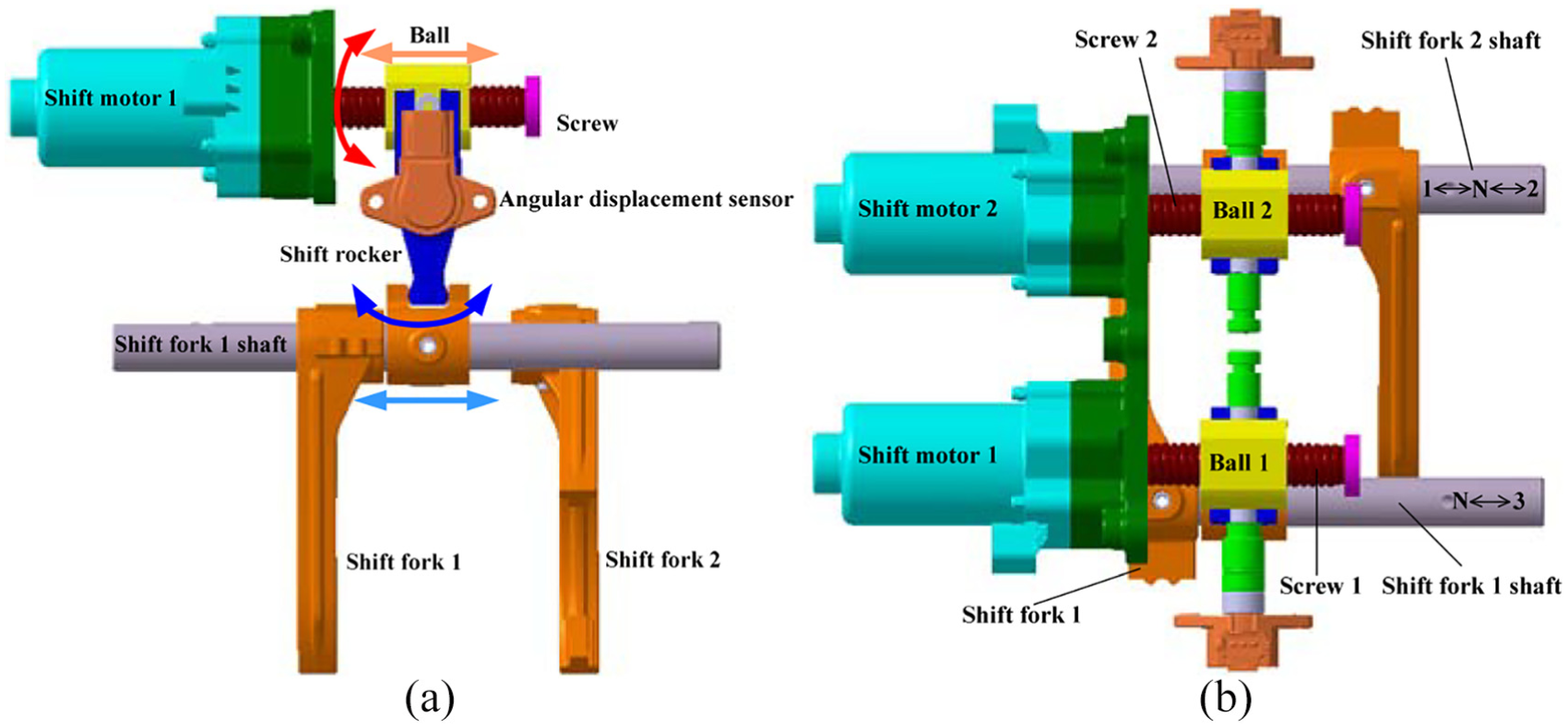
Partial structure of shift actuator: (a) shift process between N and 3 and (b) top view of shift actuator.
This system eliminates the gear selection process. Moreover, the 1-N-2 and N-3 shift actuators are completely independent of the mechanical structure. The interlock is designed in the transmission for preventing simultaneous shifting to two gears. Compared with the AMT transformed from traditional manual transmission, this structure can prevent the transmission from failing to shift due to shift motor faults. Furthermore, the structure can simplify the control logic of the shift process and thus improve shift stability.
AMT shift process based on active synchronisation of driving motor
Figure 5 illustrates the AMT shift process which actively synchronises the driving motor.
Requesting shift phase. During the driving process, TCU, which is the controller of AMT, collects speed signal and accelerator pedal opening in real time. TCU also judges whether to shift or not. When the shifting condition is met, it can send the signal of ‘requesting shift’ to the vehicle control unit (VCU), which is the vehicle controller. VCU makes the arbitration and decision of requesting shift, sends the command of ‘shift allowed’ to TCU and submits the supreme control of the vehicle dynamic system to TCU.
Decreasing motor torque phase. The AMT system based on the active synchronisation of the driving motor cancels the clutch to disengage smoothly. TCU sends the request of ‘decreasing torque’ to the motor control unit (MCU) to decrease the motor torque and ensure the stability of motor speed in the period of shifting to the neutral gear. Due to the dramatic change of the actual inertia of the motor during this process, the designed rational control algorithm is implemented to ensure that no torque output exists in the steady motor speed.
Disengaging phase. After decreasing the motor torque, TCU controls the shift actuator to shift to neutral gear. Figure 6 shows the forces between the mesh teeth during the disengaging phase. 15

Schematic of AMT shift process.

Forces between engaging teeth in disengaging phase.
Figure 6 indicates that the main resistance is due to the interaction force between the mesh gear and the sleeve, namely, Fq, as expressed by equation (1)

where Fc is the tangential force transmitted by the mesh teeth, μ2 is the friction coefficient between the spline end-face of the mesh gear and that of the sleeve, Tc is the torque transmitted by the sleeve and R is the radius of the force action point.
Tc can be expressed as equation (2)

where Jm is the rotational inertia of the motor, Jin is the rotational inertia of the transmission input shaft and direct-speed gears, Jout is the rotational inertia of the transmission output shaft and Js and Jfd are the rotational inertia of the transmission shaft and main reducer, respectively. Jw is the rotational inertia of the wheel, Jv is the rotational inertia of the vehicle, Tr is the driving resistance moment, Tm is the output torque of the driving motor, i0 is the axle ratio and ig is the gear ratio of the AMT.
Using equations (1) and (2), we can obtain the following

From equation (3), when the output torque of driving motor Tm is zero in the condition of the same running resistance, the interaction force between the mesh gear and sleeve Fq is reduced to the minimum. Disengaging is easy and convenient, and the disengaging time is the shortest. Therefore, the motor torque must be decreased before the transmission shifts to neutral gear.
1. Adjusting motor speed phase. To make the mesh gear and sleeve of the target gear in the speed synchronisation status right after disengaging, TCU sends a request to the MCU, which makes the control motor enter the closed-loop mode. TCU also selects the target speed as the goal to dynamically adjust. Moreover, TCU judges whether to meet the range of speed difference by the speed synchronisation condition of different gears.
2. Engaging phase. When the speed difference meets the shifting requirement, the shift actuator can be controlled to shift to the neutral gear by TCU in principle. However, this shift strategy does not consider the output torque of the motor because the motor works in closed-loop mode. In addition, shifting by force may cause considerable impact. Figure 7 illustrates the forces between the engaging teeth in the engaging phase.
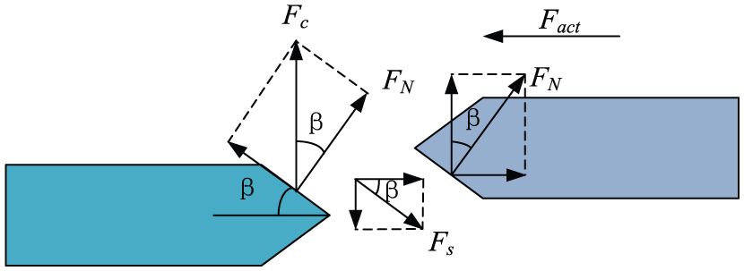
Forces between engaging teeth in engaging phase.
Fq refers to the interaction force between the mesh gear and the sleeve. The force can be expressed as equation (4)

where FN is the normal pressure of the interface, Fs is the friction between the interfaces and β is the chamfering of spline teeth. FN and Fs are expressed by equations (5) and (6), respectively


According to equations (1) and (4)–(6), Fq can be expressed as equation (7)

The condition that the transmission shifts smoothly is expressed as follows

where Fact is the shifting force acting on the sleeve.
To quickly shift to the target gear and reduce the shifting jerk, Fq must be ensured, referring to the interaction force between the engaging teeth. Equations (3) and (8) reveal that similar to the condition under disengaging phase, when Tm or the output torque of the driving motor is zero, Fq is reduced to the minimum. Fq is the interaction force between the mesh gear and the sleeve. Therefore, when the condition of speed synchronisation is met, TCU should control the motor torque before shifting. The actual output torque of the motor should be zero to ensure quick and smooth shifting without impact and noise, given that the motor speed meets the requirement of shift synchronisation.
3. Restoring torque phase. When transmission is shifted to the target gear, the motor torque should be recovered to meet the power demand of the vehicle. According to the accelerator pedal opening, vehicle speed, reference output torque and current driving state, VCU calculates the target output torque and sends the value to TCU. Then, TCU sends the request of restoring torque and the target torque to MCU to control the motor while restoring the torque on basis of no-load torque. When the output torque reaches the target torque computed by VCU, the motor directly works into the normal driving model. In addition, the vehicle returns to normal state.
Evaluation index of shift quality based on active synchronisation of driving motor
This study adopts three parameters, namely, success rate of shift, torque interruption time and jerk. These parameters serve as the evaluation indexes in our study of the AMT shift quality on the basis of actively synchronising the driving motor. 16
1. Success rate of shift. This rate is defined as the ratio between the successful shift number and the total number which can be expressed as follows
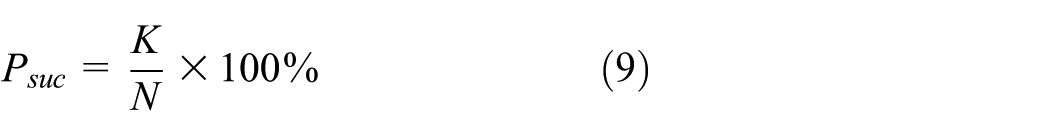
where Psuc is the success rate of AMT shift in the electric bus, 0 < Psuc ≤ 1, K is the successful shift number and N is the total shift number.
The validity and reliability of the control strategy of shifting through actively synchronising the driving motor can be verified by the success rate of shift. The rate directly affects the driving safety of the electric bus. Therefore, from the viewpoint of safe driving, the first principle of developing AMT shift control strategy is to ensure the success rate of shift.
2. Torque interruption time. Torque interruption time is defined as the time interval from the time of disengaging to neutral gear to the time of shifting to the target gear. Such time can be expressed as follows

where tshift is the torque interruption time, tN is the time of disengaging to neutral gear, tS is the time of motor speed synchronisation, tG is the shift time and tT is the sum of the communication time of each controller in the shifting process.
The shorter the torque interruption time, the shorter the acceleration time of the vehicle and the better the dynamic performance. The shorter the time of speed synchronisation, the lower the energy consumption. A short time is beneficial to improving the driving range of an electric bus. Therefore, the good shift quality requires that the interruption time be shortened as much as possible under the premise of ensuring smooth shifting.
3. Jerk. The jerk of the electric bus can be expressed as follows

where a is the acceleration of the vehicle. The acceleration can be expressed as
The jerk can be expressed as follows

Given the short shift time, we can assume that driving resistance torque Tr remains the same. Equation (12) can also be simplified as follows

From equation (13), we realise that the jerk of the electric bus is proportional to the first derivative of the motor output torque and inversely proportional to the gear. Thus, the jerk cannot be used to characterise the change of the motor output torque. The more dramatically the motor output torque changes, the greater the jerk can be. To ensure that the shifting jerk is as small as possible to meet people’s comfort requirement, sudden changes in the output torque should be avoided. When the recovery strategies of the motor torque are developed, and the recovery rate of the low gear should be less than that of the high gear.
Engaging characteristic analysis of jaw clutch
Jaw clutch is adopted instead of the synchroniser as the shift system in the electric bus AMT investigated in this research. To establish an effective model of the jaw clutch, the following assumptions are first made. 17
The system consists of an inelastic inertial element.
Each rotary part has only 1 degree of freedom.
Based on the given assumptions, mesh gears (target gears) and the parameters or variables before, such gears are transformed to mesh gears. The sleeve corresponding to the mesh gears and the parameters and variables after them are transformed to this sleeve. Figure 8 reveals the simple model of the jaw clutch shift system.

Simple model of jaw clutch shift system.
Figure 8 emphasises that J1 and J2 are the equivalent moments of inertia of the mesh gear and the sleeve, respectively. ω1 and ω2 are the angular velocities of the mesh gear and the sleeve, respectively. m2 is the mass of the sleeve, and r2 is the average radius of the engaging gear spline.
Analysis of the engaging process of jaw clutch
Jaw clutch is a shifting system that completes combination and torque transmission through direct contact friction of the spline surface given a speed difference between the sleeve and the mesh gear. Figure 9 shows the engaging process, where Δω0, Δω1, Δω2 and Δω3 are the angular velocity differences between the mesh gear and the sleeve in the beginning of each period during the engaging process. t0, t1, t2 and t3 are the end time of each period during the engaging process. S1 is the displacement of the sleeve when the splines of the sleeve and mesh gear are in contact with each other. Smax is the displacement of the sleeve when the splines of the sleeve and mesh gear are completely engaged. Φ is the backlash of the gear when the splines of the sleeve and the mesh gear are completely engaged.
1. Initial free-sliding phase. No locking mechanism exists between the sleeve and the mesh gear. Thus, it can shift in any angular velocity difference Δω0 between the sleeve and the mesh gear. Before contacting the spline surface, the torque is not transmitted by the jaw clutch. Moreover, the sleeve must only overcome the sliding friction along the axial direction. The reason is the torque loss between the internal spline of the sleeve and the external spline of the spline hub.

Engaging process of jaw clutch.
The sleeve is connected with the output shaft, and its angular velocity can be considered to remain unchanged in the shifting process. The power loss caused by the gear churning and the bearing friction make the mesh gear. In addition, the rotating parts connected with it slow down, 18 assuming that this process is the uniform deceleration process. The sliding duration of the sleeve is t1 in the initial free-sliding phase.
2. Gear tooth-surface impact phase. When the normal distance between the spline surface of the sleeve and that of the mesh gear reaches 10−4 m, a film exists between the surfaces, and the friction between the surfaces belongs to the mixed friction. When the normal distance among surfaces reaches 10−5 m, most of the lubricating oil is discharged from the surfaces. The friction is changed into the solid friction phase, and the direct impact is thought to occur between the spline of the sleeve and that of the mesh gear. Moreover, the rotation rate of the axial of the sleeve is quickly reduced to zero. The rotation speed difference between the sleeve and the mesh gear is reduced from Δω1 to Δω2. In this study, the change of the axial displacement of the sleeve is supposed to change little in the impact phase. 19
3. Gear tooth-surface friction phase. When the axial speed of the sleeve is stable at zero, the sleeve contacts with the spline surface of the mesh gear. Then, the gear friction phase begins, and the overlap of the surfaces is φfstart. When the angular velocities of the sleeve and the mesh gear are synchronous or their surface splines are disengaging, this phase is over and the overlap of the surfaces is φfend.
When the gear friction phase is over, three cases may occurr: (a) Δω3 = 0, φfend ≠ 0; (b) Δω3 = 0, φfend = 0; (c) Δω3 ≠ 0, φfend = 0. The first case represents that the revolving speeds of the mesh gear and the sleeve reach the same value in the gear friction phase. However, the surfaces of the splines never make contact with each other. Thus, the mesh gear spline cannot be engaged with the sleeve spline, and the jaw clutch fails to shift. The second and third cases represent that the overlap between the surfaces of the sleeve and mesh gear splines is eliminated. When the gear friction phase is over, shifting success is possible at this moment regardless of whether Δω3 is zero or not.
4. Spline engaging phase. The axial force situation of the sleeve in this phase is the same as the initial free-sliding phase. In the spline-engaging phase, the difference of rotating speed Δω3 is rapidly reduced to zero due to the impact of the mesh gear and sleeve splines, thereby causing the brief torsional vibration of the drive train.
Analysis of the engagement success probability and determination of the optimum speed difference
When the gear tooth-surface impact phase is completed, the circumferentially relative position of the sleeve and mesh gear splines is random. It may go directly to the spline-engaging phase without the gear friction phase, or it may go to the spline-engaging phase in the case that the mesh gear spline rotates a certain angle relative to the sleeve spline. Therefore, this study introduces random factor ξ, which represents the circumferentially relative position of the sleeve and the mesh gear splines in the beginning of the gear tooth-surface friction phase. The unit of random factor ξ is rad, and it satisfies uniform distribution in [0, 2π/n].
The change of the axially relative position between the mesh gear and sleeve splines caused by the gear impact may be ignored. The rotation angle of the mesh gear relative to the sleeve for successful shifting is determined by the overlap φfstart of the mesh gear spline surface and the sleeve surface in the beginning of the gear friction phase. Figure 10 reveals the relationship between the circumferentially relative position ξ, the circumferentially overlap φfstart of the sleeve spline surface, and the mesh gear surface in the beginning of the gear tooth-surface friction phase. Relative position ξ corresponds with overlap φfstart.

Relationship of relative position ξ and overlap φfstart.
In the beginning of the gear tooth-surface friction phase, overlap φfstart can be expressed by ξ as equation (14)

The condition of jaw clutch shifting success can be expressed as equation (15)

In this study, the shifting success probability of the jaw clutch in a certain speed difference is defined as the shift volume in that speed difference, which is expressed as follows
where psuc is the shifting success probability, n is the tooth number of the sleeve spline, p0 is the direct engagement probability of the mesh gear and the sleeve spline without contact,
Using equations (14) and (15), we can obtain the following


φfstart is a random variable. Thus, Δω3 is a variable whose value is determined by φfstart and Δω0

When ξ satisfies the inequality:
The dynamic model and the shifting volume model of jaw clutch can be built using the software MATLAB/Simulink. Figures 11 and 12 illustrate the simulation results of the shifting volume in each speed difference of the electric bus AMT.

Relationship between shift success probability and speed difference Δω1.
Relationship between shift success probability and speed difference Δω0.
Figure 11 indicates a nonlinear relationship between the shift success probability of jaw clutch psuc and Δω1. In addition, psuc increases with the increase of|Δω1|. When|Δω1| reaches a critical value, psuc is maintained at the maximum value of 1 without changing. Moreover, psuc is symmetric with respect to line Δω1 = 0. The larger the angular speed difference Δω1 between the mesh gear and the sleeve in the beginning of the gear friction phase, the larger the circumferentially relative displacement between them in the gear friction phase. At the end of this phase, the overlap of the spline surfaces of the sleeve and the mesh gear can be completely eliminated, thereby increasing the shift success probability. However, when|Δω1| increases to the critical value, the overlap of the spline surfaces of the sleeve and the mesh gear can be completely eliminated at the end of the gear friction phase regardless of the manner by which|Δω1| increases. The reason is that such an overlap has no influence on shift success probability. In the same value of Δω1, such a probability of each gear is different. The reason is that this probability is affected not only by the rotation inertia of the transmission system of each gear but also by the gear ratio.
In the free-sliding phase, the mesh gear and the sleeve are in the state of decreasing rotation. The curve motion in Figure 12 relative to the curve in Figure 11 depends on the relationship of|Δω1free|, the absolute value of the angular velocity variation of the mesh gear and|Δω2free|, the absolute value of the angular velocity variation of the sleeve. (a) When|Δω1free| > |Δω2free|, the curve in Figure 12 moves towards the right relative to the curve in Figure 11; (b) when|Δω1free| < |Δω2free|, the curve in Figure 12 moves towards the left relative to the curve in Figure 12. The case analysed in this study belongs to the latter.
Figure 12 shows that at the moment that the value of psuc reaches the value of 1, Δω0opt becomes the optimum shifting speed difference between the mesh gear and the sleeve. The math model of Δω0opt is shown as follows

where Tgloss is the torque loss of the mesh gear and the rotation parts attached to it, Tsloss is the torque loss of the sleeve and the rotation parts attached to it, r1 is the average radius of the sleeve spline and μ is the friction coefficient of the sleeve internal spline and the hub spline.
The theoretical analysis of the engaging mechanism and the proposal of the engagement success probability model provide a control requirement for the study of the motor control strategy and AMT shift. Control strategy based on the active synchronisation of the driving motor and the establishment of the good theoretical foundation are also introduced.
Shift control strategies of the driving motor
According to the analysis of the AMT shift process based on the active synchronisation of the driving motor, the accurate motor control strategy is the key to realising this shift process. The shift quality of the AMT system is also directly determined by the control performance of the motor.
In the shift process, the motor must work in various work modes and must smoothly switch. The motor must also coordinate with the shift mechanism to ensure the shift quality. In this study, the direct torque control strategy based on sliding-mode flexible structure and the algorithm of space vector pulse-width modulation are developed. The control strategy of motor without torque and the torque recovery strategy of motor in the disengaging and shifting process are developed. The aim is to meet the requirements of the high precision and high response control of the motor. The gear-shifting quality of the electric bus should also be improved.
Direct torque control strategy of induction motor based on sliding-mode flexible structure
According to the mathematical model of motor based on an α-β coordinate system20,21 and control theory of sliding-mode variable structure, 22 a sliding-mode control system based on torque and stator flux error is developed. The control signal is obtained by the space vector pulse-width modulation of stator voltage. This voltage solved the torque ripple problem and improved the motor control precision to meet the shift requirement of AMT. Based on sliding-mode flexible structure, Figure 13 demonstrates the direct torque control strategy of the induction motor.

Direct torque control strategy of induction motor based on sliding-mode flexible structure.
The phase value of stator voltage (uA, uB and uC) and the phase value of current (iA, iB and iC) output by the voltage inverter are input into the module of coordinate transformation to obtain the vector of stator voltage
Control strategy of motor without torque output based on linear quadratic Gaussian (LQG)/closed-loop transfer recovery (LTR)
A reasonable design of the control algorithm can guarantee the motor without torque output in the disengaging and shifting process. The design is greatly important to improving the shift quality of AMT. In this research, the linear quadratic Gaussian (LQG)/loop transfer recovery (LTR) control method based on optimal control, LQG of Calman filter and LTR is adopted to modify the target motor torque. This modification meets the requirements of zero torque output in the disengaging and shifting process.23,24 Figure 14 shows the control strategy based on the LQG/LTR of the motor without torque output.
Control strategy of motor without torque output in disengaging and shifting process based on LQG/LTR.
Vector
Control strategy of restoring motor torque
After completing the AMT shift process, TCU must send the requirement of restoring torque to MCU according to the current driving state and driving force of the vehicle. MCU control the motor to recover the torque. AMT system based on the active synchronisation of the driving motor has no clutch. Therefore, the power transmission system is instantaneously reconnected at the end of the engaging phase. The motor output torque is directly transmitted to the wheels through the transmission, shaft, main reducer and the drive axle.
Equation (13) shows that the jerk of the electric bus is proportional to the changing rate of the motor output torque. The jerk is also related to the gear, under the condition of a certain rate of restoring the motor torque. The higher the gear, the smaller the jerk. Therefore, the main factor that affects the jerk is the torque recovery rate and AMT gear in the process of restoring torque.
Equation (13) is only the definition formula of jerk; in the actual driving process, jerk cannot be calculated through this formula. Let the time interval of sampling Δt, ut1, ut2 and ut3, represent the driving speed at three adjacent sampling moments t1, t2 and t3, respectively. Thus, the jerk of any moment can be expressed as follows

where a1 and a2 are the acceleration values of the electric bus at two adjacent moments. Δt = t2 – t1 = t3 – t2.
In the process of restoring motor torque, the jerk of the vehicle is calculated in real time and compared with the reference value set. (1) When|jt| < |j0|, the recovery rate of initial torque does not need to be modified. (2) When|jt| ≥ |j0|, the established recovery rate of the torque must be modified to ensure that the jerk is in the acceptable range.
From the viewpoint of vehicle performance, the jerk and the torque recovery time are contradictory. If we assure that the jerk is small in terms of principle, then the jerk must reduce the rate of restoring torque which increases the restoring torque time, resulting in a decrease in the dynamic performance of electric bus. If we assure the restoring torque time and the power performance of the shift process end in terms of principle, then torque recovery must be completed as soon as possible, thereby making the jerk too large and affecting the driving comfort. Therefore, the jerk and restoring torque time should be considered when we develop the restoring torque strategy, which can ensure the vehicle’s dynamic performance.

where
The optimised function of jerk is defined as follows
where ρ(α,
The opening and change rate of the accelerator pedal mirror the driver’s requirement of jerk power and tolerance. In this study, the opening and change rate of the accelerator pedal are selected as input variables. By optimising the weight function ρ(α,
TCU controls the motor to recover torque according to the calculation of the recovery rate in real time, until the motor output torque reaches target torque
Control strategy of AMT shift process
Figure 15 demonstrates the flowchart of the control strategy of AMT shift process based on the active synchronisation of the driving motor.
When the vehicle is running, TCU determines whether the current gear is the optimal gear. If the determination result is negative, then the programme enters the requesting shift phase, in which the shift request is sent to VCU when the shift condition is met. Target gear is also sent to VCU.
The arbitration of the target gear signal sent by TCU is made by VCU according to the current vehicle status, the working status of motor and the battery status to determine whether to allow shift. If allowed, then VCU sends the command of shifting to VCU, informs other controllers to prepare for shifting and submits the supreme control of the vehicle dynamic system to TCU.
The programme enters the phase of decreasing motor torque. The programme also collects the motor output torque in real time and determines whether the motor has been in the non-torque condition. If the condition is met, then the programme enters the disengaging phase. If not, then the motor continues to decrease the torque until the condition is met.
The shift actuator is controlled by TCU to disengage, and the transmission is set to neutral gear. Moreover, TCU judges whether the transmission has been disengaged in real time by collecting the value of the gear position sensor. If the transmission has been set to the neutral gear, then the programme proceeds to the next step. If not, then the shift actuator continues act to disengage until the transmission is set to the neutral gear.
After the transmission shifts to neutral gear, the programme enters the phase of adjusting the motor speed. The speed synchronous calculation module judges the speed synchronous condition in real time, according to the optimal shifting speed difference of each gear. If the shifting speed synchronous condition is met, then the programme proceeds to the next step. If not, then it goes on with the speed synchronisation.
When the speed synchronisation is complete, the programme collects the motor output torque in real time and judges whether the motor is currently in the no-load state. If the motor output torque meets the requirement, then it directly enters the engaging phase; otherwise, it still controls the motor to adjust the torque.
The programme enters the engaging phase and makes the transmission shift to the target gear. TCU judges whether the transmission has completed shifting in real time by collecting the value of the gear position sensor. If the shifting is completed, then the programme proceeds to the next step; otherwise, it goes on with the control of shifting until the transmission is engaged with the target gear.
When the shifting is completed, the powertrain system of the electric bus is reconnected. The programme also enters the torque restoring phase. Once this phase is over, TCU submits the supreme control of the vehicle dynamic system to VCU. In addition, MCU controls the motor to directly work into the normal driving mode. Then, the vehicle returns to the normal running state. TCU judges the optimal gear again and continues to wait for the next shift.

Flowchart of control strategy of AMT shift process based on active synchronisation of driving motor.
The shift control strategy of AMT based on the active synchronisation of the driving motor is implemented under the joint work of multiple control units and the coordination control of motor and shift actuators. From the perspectives of control, this strategy ensures efficient communication between controllers. The strategy also improves the control precision of motor and shift actuator. Therefore, the shift quality of AMT and the ride performance and comfort in electric bus are improved.
Experimental verification
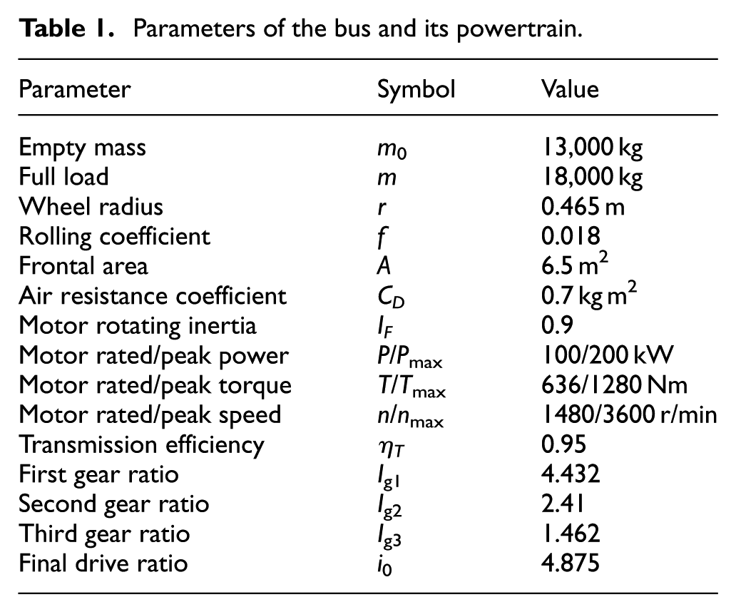
To verify the effectiveness and accuracy of the shift control strategy based on the active synchronisation of the driving motor, the prototype vehicle testing on electric bus equipped with AMT has been conducted. Table 1 presents the parameters of the bus and its powertrain. Figure 16 shows the test bus.
Parameters of the bus and its powertrain.

Electric bus for testing.
In the study, the route map of Hongzhou 17 bus is selected as the test route which is from Westlake Science Park Station to Pine Field Hexi Station. The entire journey is approximately 13.0 km. The route has 27 stations and 30 traffic lights. This route mainly concludes Zhenhua Road, Gudun Road and Tianmu Mountain Road. Zhenhua Road belongs to the unblocked road sections, whereas Gudun Road and Tianmu Mountain Road are located in the downtown section. This section belongs to the congested road sections due to several traffic lights and heavy traffic. Figure 17 presents the route map of Hongzhou 17 bus.
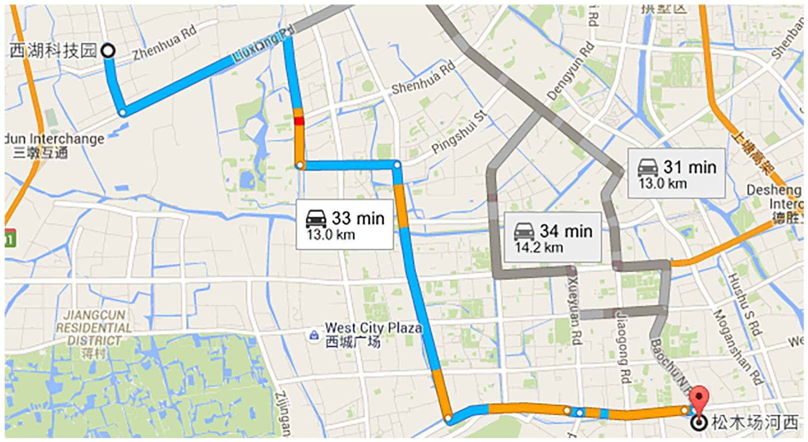
Route map of Hongzhou 17 bus.
An electric bus of a company is selected as the test bus to fully reflect the real driving situation. The test was done during peak and off-peak. According to the actual survey, the peak period was usually from 8 a.m. to 11 a.m., whereas the off-peak period was after 9 p.m. Therefore, we select such time frames as the test time. We also conduct data collection for 10 days. The driving test, covering a distance of 1131 km, 4218 parking times and 16,320 shifting times, illustrates that the driving performance is good and the shift success rate is 100%.
Figure 18 indicates that the shift time from the beginning of decreasing torque to the end of restoring torque is 1.27 s. The torque interruption time is only 0.89 s. The decreasing time of the motor torque is 150 ms, and the disengaging time is 120 ms. The phase of controlling motor speed is a little long, and its time is 580 ms, accounting for 65.2% of the torque interruption time. The actual time of adjusting motor speed is 480 ms, and 100 ms is used to control the torque to ensure that no load exists at the moment of engaging. The engaging time is 130 ms, whereas the recovery time of motor torque is 150 ms. The main shift impact on the shift process occurs in the decreasing and restoring torque phase which is consistent with the expression of shift impact. The maximum shift jerk in the decreasing torque phase is −2.131 m/s3, whereas the maximum shift jerk in the restoring torque phase is 1.523 m/s3, whose absolute value is far less than the standard value of 10 m/s3. The value indicates that the shift impact of the electric bus is in the acceptable range. The value also implies the validity of the developed motor torque recovery strategy.

Test curve of first-to-second upshift process with 74% of accelerator pedal opening.
Figure 19 shows that the total time of the gliding process from second to first gear is 0.97 s. The total time is from the beginning of decreasing torque to the end of restoring torque. The torque interruption time is 0.86 s, in which the total disengaging and shifting time is 260 ms. In addition, the time of adjusting motor speed is 540 ms, and communication time is 60 ms. The shift position curve gently changes without position overshoot at disengaging and shifting moments. The error speed between motor and target is in the optimal range, and the residual torque is close to zero after the adjusting speed. The maximum shift jerk is 1.332 m/s3 in the shift process which is far less than the standard value.

Test curve of gliding from second to first gear.
The test results of upshifting and downshifting illustrate that the shifting control strategy of AMT based on the active synchronisation of the driving motor ensure that the torque interruption time of AMT mounted to the electric bus is less than 0.9 s. The jerk is far less than the recommendation value of 10 m/s3, and no shift binding and failure phenomenon are found. Both have a good shift quality and meet the requirement of smooth shift feel and ride comfort.
Conclusion
In this research, the shifting process and AMT principle based on the active synchronisation of the driving motor, the work state of motor and the control requirement of the shifting process are analysed. The study also describes the shift quality of AMT on the basis of actively synchronising the driving motor and the impact factors on shift quality. In addition, the research determines the shift quality evaluation.
According to the shifting and engaging mechanisms of jaw clutch used in the electric bus, the engaging mechanism and dynamic characteristics of the various phases in the engaging process are further analysed. The effect factors of the shift success probability of AMT are studied. Moreover, the range of the optimal speed difference for each gear is determined.
Based on sliding-model control theory and space vector pulse-modulation method, the strategy of direct torque control based on the sliding-mode variable structure of the induction motor is developed. The no-load output control strategy of the motor with the disengaging and engaging transmission and the torque recovery strategy after shifting are also developed. In addition, the shift control strategy of AMT based on the active synchronisation of the driving motor is created.
Through road tests, the shift and control strategy based on the active synchronisation of the driving motor developed in this study are proven to reduce the torque interruption time in the AMT shift process mounted to the electric bus. The impact of shift without shift-binding phenomenon is also reduced. Moreover, the shift success rate is 100%. Therefore, a good shift quality is indicated, and the requirement of smooth shift feel and comfortable ride is met.
Footnotes
Handling Editor: James Baldwin
Declaration of conflicting interests
The author(s) declared no potential conflicts of interest with respect to the research, authorship and/or publication of this article.
Funding
The author(s) disclosed receipt of the following financial support for the research, authorship and/or publication of this article: This work was supported by the International S&T Cooperation Program of China (grant no. 2014DFA71790), the Key Scientific and Technological Project of Jilin Province (grant nos 20160519008JH, 20170204073GX, 201805200 71JH) and the Chinese High Technology Research and Development Program (grant nos 2016YFB0101402-01, 2018 YFB0104901) and Qingdao Science and Technology Program (grant no. 18-2-2-17-zhc).