
Abstract
The combustion process of one 1000-MW ultra-supercritical double-tangential-circle boiler was numerically studied and the three-dimensional full-size structure of the boiler was full considered. The influences of primary and over-fire air velocity as well as the jet structure on NOx generation characteristics were examined. In addition, the NOx generation characteristics of the improved burner structure were compared with those of the original one. Numerical results show that there exist two inverse elliptical flow fields and temperature fields. Moreover, the NOx generation and distribution characteristics are related to the temperature field to a certain extent. For different burner jet structures and arrangements, NOx distribution curves of the horizontal cross section are all W-shaped, but the NOx generation and distribution performance are correspondingly different, while the NOx emission changes are unobvious for different design schemes of the boiler burner. When we arrange one layer of auxiliary air from the burner undersurface, the flow area of the primary coal powder jet is enlarged by 100% and the coal feeding is increased by 20%. As a result, the temperature around the burner zone rises significantly. However, when two layers of auxiliary air are adopted, the combustion characteristic is promoted and NOx generation increases slightly. Based on the arrangement of the burner in the ultra-supercritical boiler, NOx generation does not vary obviously at different boiler loads. To achieve a better scheme, numerical and experimental studies are both performed in this study, and identical results are obtained. The current results may provide a theoretical basis for burner design improvement.
Introduction
Due to the promotion of steam pressure and temperature, the thermal efficiency of ultra-supercritical units is higher than that of the current units by nearly 10%, therefore it has become the main development direction of thermal power units at home and abroad. The present boiler is an improved low-NOx ultra-supercritical variable-pressure operation 1000-MW once-through boiler of the type HG-3110/26.25-YM3, adopting II-type arrangement, single furnace, balanced draft, and Mitsubishi advanced combustion technology. The Pollution Minimizing (PM-type) main burners and Mitsubishi Advanced Combustion Technology (MACT-type) low NOx combustion system of graded air supply are arranged in this boiler. It used the inverse double-tangential-circle combustion-type. The original burner adopts the light oil ignition, while, in order to save the firing up oil, the oil pistol ignition may be changed as the combination of tiny oil ignition and oil pistol ignition during the equipment modification phase. As the ignition type changes, the primary and over-fire air (OFA) jet shapes and arrangements should be improved correspondingly. This study carried out a numerical simulation on NOx generation and emission under different primary and OFA jet shapes and arrangements, providing a theoretical basis for burner design improvement; therefore, it is meaningful for both burner design and boiler operation.
It is hard to measure NOx variation situation inside the furnace for the thermal state tests, and the workload is huge.1–3 However, the numerical simulation can detail NOx generation characteristics during combustion in the furnace and has been widely used in the related research.4–6 double-circle tangential-firing boiler of 1000-MW ultra-supercritical unit has been a research hotspot, such as C Shen et al. 7 and Z Gao et al. 8 studied this kind of boiler coal powder combustion and NOx emission, respectively, by numerical simulation method. 9 Three-dimensional (3D) full-size structure and large air bellows were full considered in this article. The numerical results are consistent with the experimental data so that the numerical method can correctly adopted to predict the boiler NOx generation characteristics.
Simulation domain and computing method
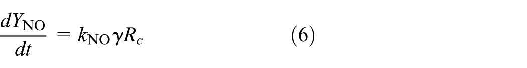
Simulation domain
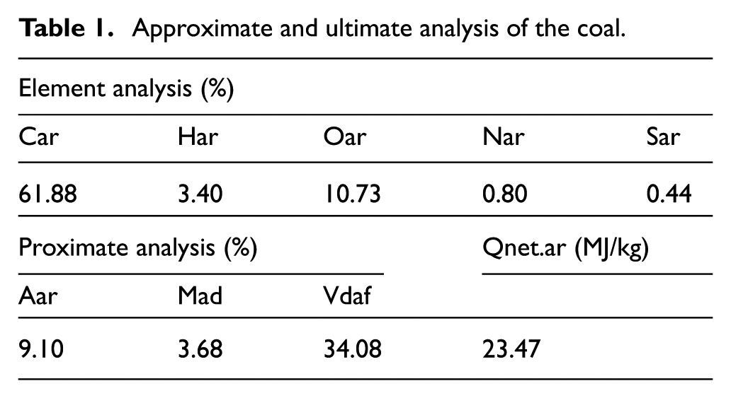
The width, depth, and height of the simulation boiler furnace are 34.22, 15.67, and 66.60 m, respectively. This boiler adopts the medium-speed coal mill positive-pressure direct-fired powder manufacturing system, consisting of six medium-speed coal mills (five for operation and one for stand-up under boiler maximum continuous rating (BMCR) conditions). The industrial coal analysis is shown in Table 1. As shown in Figure 1, the octagonal inverse double-tangential-circle combustion-type is used in this boiler, and there are total four burners arranged in the front and back wall named no. 1–no. 8. For the original design scheme, every corner consists of six layers of PM-type bias burners named A, B, C, D, E, and F from the bottom to the top. In the height direction, a total of 14 layers of auxiliary air (AA) supply openings (OFA) are arranged. Above the top AA supply opening, there are two layers of OFA air supply openings; eight layers of AA air supply openings at the 2.6- to 7.2-m position upward from the top coal powder jet are also arranged.
Approximate and ultimate analysis of the coal.

Horizontal burner arrangement of the furnace.
Mesh and computational fluid dynamics model
The computing zone employs tetrahedral cells. The calculation domain includes the whole furnace which is the neighborhood of the burners, upper furnace zone, and lower furnace zone. Mesh is refined in the furnace combustion zone where the combustion processes actively take place. The nozzle of primary air, AA, OFA, secondary air, and wall are meshed, respectively.8–11 The total number of grids adopted is 9.78 × 10⁵. When it increases to 11.78 × 10⁵ or even larger, the maximum change of the calculated velocity magnitude in the examined horizontal plane is less than 1%. The calculated velocity fields in the examined horizontal plane using 9.78 × 10⁵ and 11.78 × 10⁵ grids are shown in Figure 2(b). After this mesh independent verification, the mesh system is set to consist of 9.78 × 10⁵ cells. The modification scheme and the calculation domain are all shown in Figure 2.

The modification scheme and calculation domain: (a) the computing zone grid of the whole furnace and burners, (b) calculation velocity fields before and after increase in the mesh number (left: 9.78 × 10⁵, right: 11.78 × 10⁵), and (c) burner original structure and improved structure.
The realizable k-ε model was used to consider the turbulence flow. The log-law wall-function method is adopted to couple with the near-wall zone. The mixture-reaction/probability density function (PDF) is used to simulate the gas-phase turbulence combustion. The P-1 radiation model is used to compute the radiation heat transfer. The single-step reaction model is adopted to simulate the volatile emission. The dynamic/diffusion combustion model is used to compute the coke combustion. The stochastic tracking model is adopted in tracking coal particle, and the particle distribution obeys Rosin–Rammler rule. The continuity equation, momentum equation, energy equation, and specific model equations are available in literatures.11–15 For the NOx generation post treatment, the convergence criterion for normalized residual of individual equation is set to be less than 10−4.
NO simulation model
The NOx generation of the coal powder boiler is composed of thermal NOx, prompt NOx, and fuel NOx. NOx generation mechanisms are available in literatures,12–18 and the main computing basis is as follows.
The generation processes of fuel NOx are:
The fuel nitrogen is mainly distributed in coal char and volatile components. The nitrogen compounds in volatile components are NH, NH2, NH3, CN, and HCN, and the major releasing form is the nitrogen in the coke converted to NO directly. According to the combustion conditions and the type of coal used in the boiler, the ratio of volatile nitrogen and coke in fuel nitrogen is predicted, while the ratio of volatile nitrogen converting to HCN and NH3 can be obtained. Nitrogen in the volatiles is converted into HCN


HCN is converted to NO


Nitrogen in the coke is converted into NO

where
The thermal NOx adopts the extended Zeldovich mechanism, and the NOx generation rate is

where
The prompt NOx generation takes the NOx component transport equation into account and its generation rate is
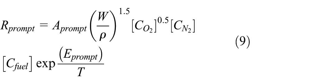
where
Boundary conditions and optimization scheme
This study is based on the rated load operating mode, where five or six layers of burners could be put into use. Therefore, six layers of burners, named A, B, C, D, E, and F, are arranged. The excess air ratio is 1.15. The coal feeding mass rate is 96 kg/s, the primary air mass rate is 177 kg/s, the OFA mass rate is 665 kg/s, AA air mass rate is 129 kg/s, and the over-fire mass rate of the main combustion zone is 450 kg/s. The primary air temperature is 348 K and the OFA temperature is 607 K. For other conditions, the air mass rates are determined based on the air mass rate related above according to the load and excess air ratio. The original and improved schemes are shown in Table 2. Every scheme is based on the rated load operating mode.
Explanation of the original and improved schemes.

Results and discussion
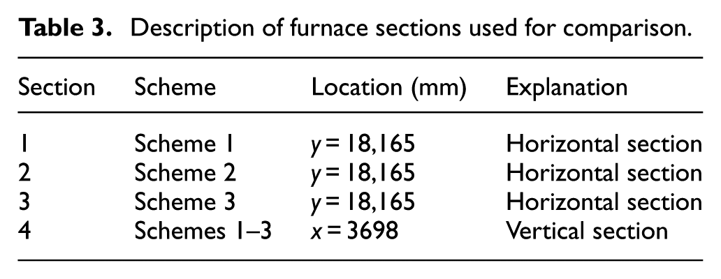
So as to achieve a convenient comparison, x, y, and z axes are defined as the furnace width, height, and depth directions, respectively. The middle position of the furnace width direction is set as x-axis 0 point, the front wall position is z-axis 0 point, and the bottom of the boiler furnace is set as z-axis 0 point. The A, B, C, D, E, and F burners’ elevation (intermediate position of deep and thin burner) of the furnace are 17,807, 19,379, 22,452, 24,023, 27,097, and 28,668 mm, respectively. Different cross sections used for comparison are shown in Table 3.
Description of furnace sections used for comparison.
The velocity and temperature fields analysis
The simulation results show that in the original and improved burner structures conditions, the furnace horizontal cross-section velocity field and flow field perform as elliptical shapes, and the gas flows of both furnaces display certain regularity. Taking the improved layer burner as the research objective, a comparison of the original (shown in Figure 2) and improved schemes 2 and 3 indicates that scheme 3 will get a better aerodynamic field in the furnace. The horizontal cross-section velocity fields at the primary air supply opening are shown in Figure 3.

Comparison of velocity fields at y = 18,165 mm cross section (unit: m/s): (a) section 2 and (b) section 3.
Under the thermal state conditions, a double-tangential-circle flow field with a high degree of symmetry is generated in the furnace and both fields are elliptical shaped. For each burner, the obvious inflection occurs as the jet fluid bears the brunt of the upstream burner jet and the lower burner flow, thus the furnace fullness degree of the gas flow is fairly good. For the schemes 1–3, due to the repaid coal powder combustion at the position of 450 mm behind the primary air supplying jet, the primary air velocity is promoted to 37 m/s. The air velocity distributions of no. 1–no. 8 corner primary air supply jets are as follows. For the scheme 1, the air supply velocity of corner no. 1, no. 6, no. 7, and no. 4 decreases to 22 m/s at the distance of 3015 mm. For the scheme 2, the distance is 3050 mm; while for the scheme 3, the distance is 3200 mm. For the scheme 1, the air supply velocity of corner no. 2, no. 5, no. 8, and no. 3 decreases to 22 m/s at the distance of 3760 mm. For the scheme 2, this value is 3800 mm; while for the scheme 3, this value is 4100 mm. The data above declare that the primary air of scheme 3 has stronger inflexibility and better fullness. At the side with back to fire of each jet, there exists significant back flow. Both tangential circles show strong independence and display only energy conversion but no mass exchange.
Taking the improved layer burner as the research objective, the improved schemes indicate that scheme 3 will be better temperature field in the furnace by comparison. The horizontal cross-section temperature field at the outlet of the improved burner structure is shown in Figure 4. The vertical sectional temperature fields in the furnace of the original and improved schemes are shown in Figure 5. As seen from the horizontal cross-section temperature field at the burner (elevation height y = 18,165 mm), for schemes 2 and 3, the temperature of the position 350 mm away from the water wall around corner no. 1, no. 6, no. 7, and no. 4 is lower. For scheme 2, the temperature is 915 K; while for scheme 3, the value is 930 K. However, the temperature of the position 350 mm away from the water wall around corner no. 2, no. 5, no. 8, and no. 3 is somehow higher.

Comparison of temperature fields at y = 18,165 mm cross section (unit: K): (a) section 2 and (b) section 3.

Comparison of temperature fields at x = 3698 mm vertical section: (a) section 1, (b) section 2, and (c) section 3.
Compared the improved schemes, for scheme 2, the temperature is 1290 K; while for scheme 3, the value is 1300 K. The cross-section average temperature of scheme 2 is 1210 K; while for scheme 3, the value is 1235 K. Moreover, the stiffness of flame aerodynamic field of the furnace is increased, and the hearth fullness of the flame in burner area is greatly improved. These indicate that scheme 3 performs a sufficient combustion. During the normal operation, the flame combustion at the burner outlet is stable and no divergence phenomena appear, so the improved structures can meet the operation requirements. Shen et al. have carried out an experimental study on the 1000-MW tangential boiler’s original burner,7–8 revealing results consistent with those of this research.
The oval temperature and flow fields rotating oppositely generate in the furnace respectively. The primary and secondary air velocities have a great impact on the thermal flow within the burner’s combustion area. Diameter of the tangent circle decreases with increase in the primary air velocity but increases with increase in the secondary air velocity. The nozzle shape and layout of the burner can change the temperature field in the furnace largely. Increasing the dimension of the primary air nozzle can increase the rigidity of the flame and avoid the flame inclination to the wall at low primary air velocity. Thus, it is the best improvement solution to primary air velocity. Thus, scheme 3 is the best improvement solution.
NOx generation of the furnace horizontal
Based on the design operation conditions, in total three layers of burners are adopted, that is, burner A, B and C, when operating at 60% load. The burn coal feeding mass rate is 63 kg/s and the air distribution is conducted referring to the base conditions. Taking the improved layer burner as the research objective, the horizontal cross-section NOx distribution field at y = 16,768 mm is shown in Figure 6. As shown in Figure 4, the NOx generation has a certain consistency with the temperature field. In the high temperature zone, the NOx generation amount is relatively large, while in the tangential circle central zone no NOx is generated there due to the relatively low gas flow temperature. At the furnace outlet, the NOx cross-section average value is 221 mg/m3. For scheme 3, the NOx generation situation is similar to that of scheme 2, while for scheme 3 the amount of NOx generated is lightly higher than that in scheme 2, and its NOx cross-section average value is 226 mg/ m3. The relatively more NOx for scheme 3 is due to the introduction of the lower layer auxiliary; the much improved layer combustion and the obviously higher burner zone temperature zone. This trend could be clearly observed from Figure 4.

Comparison of NOx mass fraction at y = 18165 mm cross section: (a) section 2 and (b) section 3.
Moreover, because of the larger air supply amount, the fuel NOx generation amount increases as well. Comparing Figure 5 with Figure 8, both perform with the similar regularity on NOx generation in the improved burner zones.
Based on the design conditions, there are in total six layers of burners named A, B, C, D, E, and F when operating at 100% load. The excess ratio is 1.15, and the coal feeding mass rate is 96 kg/s. The air distribution was adopted due to the basis conditions. Taking the improved layer burner as the research object, horizontal cross-section NOx distribution curves of various schemes at y = 18,165 mm (elevation height of the bottom burner central line) are shown in Figure 7.

Comparison of NOx generation with six layers of burners arranged: (a) section 1, (b) section 2, and (c) section 3.
For all schemes, the horizontal cross-section NOx distribution curves are all W-shaped, while the improved schemes perform more significantly. The NOx generation amount of scheme 2 is larger than that of scheme 1 because the coal feeding amount of scheme 2 is larger by 20%, leading to more fuel NOx generation. Besides, the increase in the amount on coal feeding may cause an increase in the burner zone temperature, so that the amount of fuel NOx generation may rise slightly. Compared with scheme 2, the amount of NOx generation of scheme 3 is larger, because the introduction of low-layer AA promotes the amount of coal combustion air supplied. Meanwhile, compared with scheme 2, the burner zone temperature of scheme 3 is higher, leading to more NOx generation. However, this promotion is unobvious when compared with scheme 2. According to the calculation results of aerodynamic field and temperature field, scheme 3 is verified to be the best burner structure in this study.
NOx generation of the furnace vertical section
Based on the design condition, there totally are six layers of burners named A, B, C, D, E, and F when operating at 100% load. The excess ratio is 1.15, and the coal feeding is 96 kg/s. The air distribution was adopted due to the basis condition. Repeated from after Figure 7, NOx generation of the original (scheme 1) and improved boilers (schemes 2 and 3) were all studied. The vertical cross-section NOx distribution field at x = 3698 mm (0 point at the furnace center) is shown in Figure 8.

Distribution of NOx mass fraction at cross section 4: (a) scheme 1, (b) scheme 2, and (c) scheme 3.
The comparison of aerodynamic field, the temperature field, and NOx generation characteristics indicate that scheme 3 is the best burner structure, and the overall distribution on the scheme 3 NOx distribution in the furnace will be compared with the original structure. It can be seen that the NOx generation changes of the improved burner zone are very severe. Area average NOx generation amount at the original furnace outlet is 331 mg/m3 not area unit, while the value is 335 mg/m3 for the improved scheme 3, apparently no significant decrease. Because low NOx generation and emission design on the PM-type tangential-circle combustion were adopted, the influence of the burner improvement on NOx generation and emissions is not obvious. After comparison between the original and two improved structures, NOx generation characteristic distribution along the furnace height direction performs with the same regularity, meanwhile the peak value of NOx generation is located at the middle or upper burner zone, which is consistent with results of other scholars.18–20
Based on the design conditions, the air is 129 kg/s and the excess ratio is 1.15. Figure 9 shows the average oxygen concentration distribution curve along the furnace height direction. The results show that the oxygen distribution trends along the furnace height direction of the original and improved burners are almost the same. In the main burner zone (lower than 28 m), the average oxygen concentration of the flow gas shows no significant increase, but rather an obvious decrease along the furnace direction, revealing that the full combustion consumes a lot of oxygen. At the back of the main combustion zone, NOx concentration starts to decrease due to the presence of hardly any coal powder and air introduction. At the position higher than 39 m, NOx generation decreases significantly after AA air injection.

O2 distribution of the original and improved burners at the cross section 4.
Figure 10 shows the NOx distribution curves of different horizontal sections along the furnace height direction. Due to variation in NOx concentration distribution along the furnace direction of the improved burner, the furnace could be divided into the concentration rapid increase zone, the slow increase zone, the rapid decrease zone, and the slow increase zone. The 18- to 25-m segment belongs to the NOx concentration rapid increase zone, that is the A-, B-, C-, and D-layer coal powder input zones, where NOx concentration increases rapidly with the continuous coal powder introduction. NOx concentration increases rapidly as well in this segment as shown in Figure 8, revealing that NOx concentration increase is caused by the continuous coal powder introduction. It also can be inferred from the simulation results that there is about 18.5% thermal NOx generation and the main component is fuel NOx.

NOx distribution of the original and improved burners at the cross section 4.
At the 25- to 28-m segment (D- and E-layer burner zones), NOx concentration increases slowly. C and H from the coal powder could also restore NOx in the flow gas, thus it reduces the flow gas NOx concentration. Because this furnace is at the less oxygen combustion state, no significant NOx could be generated.
At the 28- to 32-m segment, NOx concentration shows a rapid decrease trend. The air supply to this segment occupies 30% of the main burner zone. Figure 8 shows that the NOx concentration of this segment is around 26%. NOx generation occurs there indeed, although the value is small. The unburnt coal powder could restore NOx in the flow gas theoretically, but it cannot balance the NOx generation.
At the segment above 39 m, NOx generation increases by small steps. In this segment, there is no air supplied resulting in the disappearance of the dilution effect. Due to the relatively high flow gas temperature, the combustible components in the coal are fully burnt and the reduction action of hydrocarbon compounds on NOx disappears. In addition, because of the existence of oxygen in the flow gas, NOx (such as the thermal power–type NOx) may be generated there and its concentration may increase slightly as well.
Effects of burner layout on NOx generation
The boiler has six layers of burners. In this simulation, the burners are not isolated.9,10 When operating at 60% load, three layers of burners could meet the operational requirement. Two burner arrangement methods (opening A, B, and C or D, E, and F) are considered in this article. As shown in Figure 11(a), NOx distribution curves indicate that the amount of NOx generation by opening the A, B, and C burners is larger than that of opening D, E, and F. The reason is that when using the upper burners, the middle air and OFA corresponding to the lower burners are not closed completely; air from the lower jets brings in abundant oxygen to react with the coal powder so that the fuel NOx is rapidly generated; thus, the NOx concentration is relatively high.

NOx distribution of the improved burners in the boiler under different burner arrangements at the cross section 4: (a) 60% load condition of the boiler, (b) 80% load condition of the boiler, and (c) 100% load condition of the boiler.
When operating at 80% load, four layers of burners should be adopted, while the number is five at 100% load. Figure 11(b) and (c) shows the NOx distribution curves of various burner arrangements at 80% and 100% loads, respectively. It can be seen that NOx generation by adopting the upper burners is higher than that of using the lower burners, which is in agreement with the 60% load condition results. As seen in Figure 11(a)–(c), the NOx generation increase is not proportional to the load variation; however, the influence of the burner arrangement is much more significant. In order to avoid the thermal deviation caused by the operation of the lower burner to ultra-supercritical boiler, the use of the lower burner for each load is reduced. According to ultra-supercritical boiler burner being arranged, NOx generation does not increase.
Industrial test research
Cold-state test
In the industrial test, Re is 1.8 × 10⁵ through theoretical computation. According to the similarity principle, the primary and OFA velocities at cold state are used to simulate the characteristic gas flow.17–19 As shown in Figure 12, the streamer is arranged at the A burner face. The characteristic gas flow under different conditions could be achieved through analyzing the velocity at different streamer measurement points. The tests reveal that two inverse elliptical flow fields are generated in the furnace, as shown in Figure 13. This phenomenon may be caused by the burners’ orthogonal arrangement, which creates hot and cold corners. The air dynamical field is consistent with the simulation results, showing that the numerical study could correctly reflect the burner flow field trend changes.

Sketch of the ribbon location.

The gas flow fields of the burner zones along the boiler left side in the cold state: (a) width directions of the boiler and (b) depth directions of the boiler.
Hot-state test
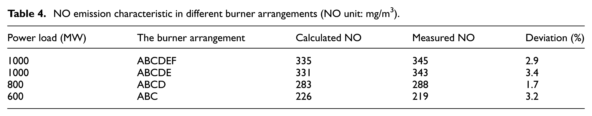
Keeping the excess air ratio stable, three layers of burners (A, B, and C) are arranged at 60% load when using the basis condition air distribution, while the value is four (A, B, C, and D) at 80% load and the value is five (A, B, C, D, and E) at 100% load. The condition of opening all six layers of burners is also conducted.18–21 As shown in Table 4, the experimental NOx concentration is compared with the numerical data, showing good conformity. According to ultra-supercritical boiler burner arranged, the operation of the lower burner is reduced under various load conditions, and a layer burner is mainly used for starting boiler, so scheme 3 is the best burner structure. Compared with the experimental data, the deviation of the numerical results is less than 10%, showing good consistency with the actual operation. The simulation can correctly reflect NOx generation characteristics in the tube, showing that adopting computational fluid dynamics (CFD) methods to study NOx generation is feasible.
NO emission characteristic in different burner arrangements (NO unit: mg/m3).
Conclusion
The numerical results show good agreement with the industrial operation qualitatively, indicating that it is possible to carrying out CFD studies on NOx generation characteristics under various combustion conditions.
The nozzles shape and layout of the burner can change the temperature field in the furnace largely. Increasing the dimension of the primary air nozzle can increase the rigidity of the flame and avoid the flame inclination to the wall at low primary air velocity.
For each scheme, NOx concentration distribution trends at the horizontal cross section all appear W-shaped, while the phenomenon is more significant for the improved schemes. According to NOx concentration distribution along the furnace height direction, the furnace could be divided into a concentration rapid increase zone, a slow decrease zone, a rapid decrease zone, and a slow increase zone.
The burner arrangement under load variation conditions is one key factor influencing NOx generation. For each load, NOx emissions are relatively low when opening the lower layers of burners, especially for the low loads. Under the low-load conditions, the OFA of the middle and upper layers could be recognized as AA air of the lower layers of burners.
NOx changes after the boiler promotion are unobvious. Compared with the rotational flow boiler, the central coal feeding tangential–circle burner shows no significant changes in NOx generation. According to ultra-supercritical boiler burner arranged, NOx generation does not increase.
Footnotes
Handling Editor: Kai Bao
Declaration of conflicting interests
The author(s) declared no potential conflicts of interest with respect to the research, authorship, and/or publication of this article.
Funding
The author(s) disclosed receipt of the following financial support for the research, authorship, and/or publication of this article: This work was supported, in part, by the Center High School Basic Scientific Research Operation Expert Foundation Project 09ZG02, Science and Technology Commission of Shanghai Municipality (STCSM; No. 16020500700), and, in part, by the Fundamental Research Funds for the Central Universities.