
Abstract
This research article proposes a novel approach called Distributed Reconfigurable B to specify and verify distributed reconfigurable control systems using B method. Reconfiguration signifies the dynamic adaptation of the system behavior to the evolution of its environment by applying a reconfiguration scenario. A multi-agent architecture is defined to affect a reconfiguration agent to ensure local reconfiguration for each subsystem and a coordination agent to manage the different subsystems to guarantee the coherence of the whole system. A reconfigurable system is a set of B operations where only a subset is executed by adding or removing operations after a well-defined reconfiguration scenario. Distributed Reconfigurable B defines two complementary steps to be applied in abstract model of B method: specification and verification. The first step models the agents according to Distributed Reconfigurable B formalism. The second verifies distributed reconfigurable control systems using Atelier B tool and avoids the redundant checking of different B machines by applying the implemented Check Reconfigurable B tool. We apply the contributions on the two benchmark production systems: FESTO and EnAS.
Keywords
Introduction
The development of distributed control system (DCS) is not an obvious task as a failure can influence the safety of human being, for example, railway and air traffic control. The requirements in DCS are increasingly growing in term of flexibility and agility.1–4 Indeed, one of the most significant challenges is the compromise between the rapid response and performance to market changes and customer needs. The reconfiguration of DCS is one of the most promising directions to address these issues. 5 Reconfiguration means the capacity of the system to change its behavior at run-time. We distinguish two types: (a) static (offline) is applied before the system cold starts 6 and (b) dynamic (online) is applied automatically at run-time. 7 It can be manually executed by users 8 or automatically performed by intelligent agents 9 that can be physical resources (robot, machine, etc.), or logical resources (scheduler). A lot of research are interested in reconfiguration,10–13 the research reported in Mouawad et al. 14 deals with the parameterized complexity of reconfiguration problems. Also, the work of Bhattacharyya et al. 15 evaluates in empirical way three different kinds of formalisms according to their suitability to model and analyze dynamic reconfiguration of dependable systems. Moreover, the study of Zhang et al. 16 presents a reconfiguration method for shipboard zonal power systems.
Formal methods based on mathematical techniques motivated many scientific researches and attracted increasing interests in industry since they proved their effectiveness to specify, develop, and verify critical systems. The work reported in Ghosh et al. 17 uses formal methods to validate and test point prioritization in railway signaling logic. Babin et al. 18 use the event-B method to design correctly the web service compositions in the case of failures. The work reported in Ni et al. 19 uses a formal model to specify real-time embedded systems following Z notation. We are interested in this research work in B method since it covers software processes from the abstract specification to the executable implementation. Furthermore, B has been successfully used in some major safety applications such as METEOR. 20 smart cards, 21 automotive diagnostics, 22 electronic circuits, 23 medical systems, 24 and electronic voting machines. 25 Also, a strong point of B is to have robust and useful tools to support the specification, design, proof, and code generation such as Atelier B. 26
In this article, the goal is to propose a new Distributed Reconfigurable B (DReconf-B) approach that improves B method in order to model and verify dynamic, automatic, and flexible distributed reconfigurable control systems (DRCS). We propose a multi-agent architecture where we assign to each subsystem a reconfiguration agent
To the best of our knowledge, this is the first contribution dealing with the B method to dynamically and automatically reconfigure distributed industrial control systems based in multi-agent architecture. The originality of this research, compared to related and previous works, concerns the proposition of a new approach based on B method and multi-agent architecture for specification and verification of automatic and flexible DRCS. We minimize also the number of operations to be checked to avoid the redundant verification of B machines.
We present in the second section, the background in which we introduce the B method and an overview of the related works. In the third section, we give the formalization of DRCS. We define in the fourth section, the new DReconf-B approach to model and verify DRCS and we apply all contributions of this work to the two case studies, FESTO and EnAS. We conclude by a conclusion and some future work.
Background
The proposed approach is based on B method. We briefly recall in this section the basic concepts of B method and present some related works.
Presentation of B
The B formal method is developed by Abrial. 29 It covers all the aspects in the software development of a system: specification, refinement, and code generation, as shown in Figure 1.

B method.
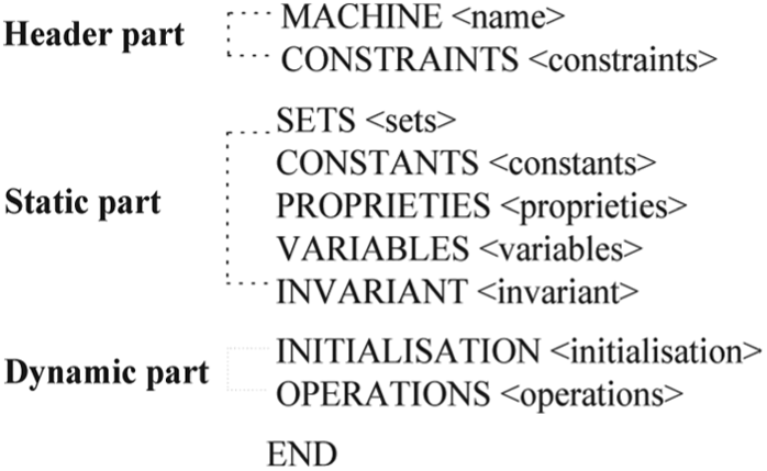
Set theory and generalized substitution are the basis of the B method to model data and to describe state modification. A robust and useful tool named Atelier B is generated for the development of B formal models. The specification step consists in translating the software requirement into an abstract machine which is composed of the following three parts (see Figure 2):
Header part. Describes by means of the clauses MACHINE and CONSTRAINTS. The clause MACHINE introduces the name of the machine optionally followed by parameters. The clause CONSTRAINTS allows us to precise the types of the parameters.
Static part. Describes by means of the clauses SETS, CONSTANTS, PROPERTIES, VARIABLES, and INVARIANT. The clauses SETS and CONSTANTS introduce the sets and the constants of the B machine, respectively. The clause PROPERTIES introduces the properties which contain the effective definitions of constants. The clause VARIABLES defines the variables which constitute the various components of the state of the machine. The clause INVARIANT defines the invariant which is a logical statement making clear what the static laws of the system are. Also it is described according to variables using set theory and predicate calculus.
Dynamic part. Describes by means of the clauses INITIALISATION and OPERATIONS. The clause INITIALISATION makes possible the initialization of variables machine. The clause OPERATIONS contains a list of the various operation specifications. An operation modifies the B machine state within the limits of the invariant. The specification of an operation is described with a generalized substitution language (GSL). An overview of GSL constructs and their syntax definition is given in Table 1. Let P1 and P2 be the predicates, Sub be the substitution, and var be the variable.
Abstract B machine structure.
Some constructs of the GSL.

GSL: generalized substitution language.
The refinement step consists in refining the abstract model of a software system into another mathematical model that is more concrete. As explained in Figure 3, we refine the model in different steps by adding more details to obtain a deterministic version named implementation.

Refinement step.
The code generation step consists in translating automatically with the Atelier B tool all the implementations of the concrete model into C code.
Composition in B
Abstract machines can be combined through the clauses INCLUDES, SEES, IMPORTS, and USES to build new specifications. 29 They appear in the static part of the abstract B machine before the clause SETS. We are especially interested in the clause INCLUDES which allows a machine to be included in another one with read/write access to the variables of the included machine. M2 machine includes M1 machine means that M2 has full access to the constants, sets, variables, and operations of M1 and operations of M2 can be defined using any M1 operation. It is worth mentioning that an operation of the including machine can call only one operation of the included machine. In order to avoid an obvious clash, we have the possibility to rename a machine while including it. This is done simply by prefixing, in the clause INCLUDES, the name of the machine we want to rename with a certain identifier by a dot. This has the effect of renaming accordingly all the variables and operations of the concerned machine.
Example 1
As shown in Figure 4, the machine M(x,n) is obtained by coupling two renamed copies (prefixed with x. and y.) of the machine M1. The operation C calls at the same time the operations x.A and y.B from the included renamed machines x.M1 and y.M1.

Clause INCLUDES.
Related works
Currently, significant research works have been interested in the development of reconfigurable systems. Zhang et al. 30 deal with the formal modeling and verification of DRCS. They develop a hierarchical multi-agent architecture where each agent is affected to a device to manage its local automatic reconfigurations, and coordinators harmonize running devices. They develop the concept of change ratio to guarantee the safeness and the determinacy of the whole system when multiple reconfiguration requirements rise simultaneously. They propose a novel judgment matrix for every reconfiguration requirement to cope with the coherence of running devices and develop an optimal layer-by-layer verification method. For reconfigurable distributed embedded control systems, Khalgui et al. 31 propose a multi-agent architecture optimization that affects a reconfiguration agent to each device in order to apply local reconfigurations and proposes a coordination agent for the coordination between different devices. A communication protocol is proposed to manage agents following the defined coordination matrices and is implemented with a java-based tool. The work reported by Khalgui et al. 32 is about reconfigurable multi-agent distributed embedded control systems using the component-based international industrial standard IEC61499. They propose a communication protocol to coordinate agents by defining coordination matrices. They define a formalism based on Petri nets to model the agents and validate the coordination between agents by applying the model-checker named SESA.
We remark that the majority of the proposed approaches in the literature are based on multi-agent architecture to develop reconfigurable systems in order to ensure the required flexibility and agility.
On the other hand, formal method is a topic that has mobilized a large community of researchers for many years. The work reported by Méry and Singh 24 proposes an Event-B refinement-based methodology to design complex medical systems. It combines formal verification, model validation using a model-checker, and refinement chart. The research reported by Méry and Singh 33 applies a model-driven development (MDD) technique that combines the semi-formal notation (unified modeling language (UML)) with the formal modeling language (Event-B) to design critical systems. This approach verifies the system using a model-checker and generates automatically the code from the verified formal specification. Su and Abrial 34 propose three approaches to model aircraft landing gear following the Event B notation. Also, they demonstrate that each proposed approach is efficient compared to a previous one in terms of proof obligations. The work conducted by Mosbahi et al. 35 develops and verifies liveness properties of reactive systems following the Event-B method. Their objective is to use two verification approaches: theorem proving which associates the Click_n_Prove tool to the Event-B method and model-checking which concerns TLC for TLA+ models. The work reported by Déharbe 36 presents an approach that generates the input language of a category of automatic theorem provers known as SMT-solvers from a class of proof obligations in B and Event-B. Proof obligations are handled with Booleans, integer arithmetics, basic sets, and relations. Also, a plug-in for Rodin that simulates the process is implemented.
The work reported by Mentré 37 proposes an approach to transform SysML structural diagrams, BDD and IBD with constraints into a B method. Ledru and collegues38–40 translate into B formal language the safety and functional models in order to validate a huge set of security scenarios. They implement a tool to perform this translation and apply the contributions of their work to the security policy of a medical emergency information system. The research reported by Déharbe and Merz 41 is interested in behavioral aspects of artifacts produced in design software components which are developed by Isabelle/HOL theory following B method. They formalize semantic objects and describe interpretation of the B method of the used concepts. Furthermore, they tackle the problem of B component composition. The study by Barbosa and Déharbe 42 aims to facilitate the use of formal methods in the industry. The authors develop and present a method which generates automatically from programmable logic controllers (PLCs) programs B models and verifies them as regard of safety constraints. De Matos et al. 43 focus on the development of B-based testing approach (BETA). BETA is a tool-supported approach which generates test cases from B method specifications by applying input space partitioning and logical coverage criteria. They evaluate the BETA applicability to solve problems with different characteristics and they apply techniques of code coverage and mutation analysis in order to measure the quality of the generated test cases. Abrial et al. 44 provide an approach to develop mathematical models of distributed algorithms using event-driven approach with the B Method. A series of refined models are developed and proved with the Atelier B to ensure the internal consistency and correctness of each model. The study by Lanoix et al. 45 proposes an approach that combines proof and model-checking to support the modeling of concurrent component-based systems and to validate their dynamic reconfigurations. A generic B model is proposed for component architectures and the consistency of the model architectural constraints is proved. Also, consistency and some temporal properties of the instantiated general model have been model-checked.
The research conducted by Kacem et al. 46 proposes a formal methodology to design multi-agent systems (MAS) following stepwise refinements. Also, it defines a formal language that combines Z notation and linear temporal logic to model the individual agent aspects as well as their exchanged collective aspects. Simonin et al. 47 specify and verify MAS for formulating the influence/reaction (I/R) model following the B method. They propose four formal patterns that design the main components of MAS and their dynamics: (a) two patterns specify the cycle of I/R model, (b) one pattern specifies the agents behaviors, and (c) one pattern specifies the environment evolution. Also, they verify their local and global properties. The research reported by Pereverzeva et al. 48 presents a formal approach to develop MAS by refinement in Event-B. They model the agent interactions and verify their safety and correctness. The work reported by Ball and Butler 49 deals with the formal modeling of fault-tolerance MAS in Event-B. A number of modeling patterns is presented which model the specifications of multi-agent interactions. Tarasyuk et al. 50 demonstrate the efficiency of Event-B to develop the dynamic reconfiguration and cooperative error recovery of a fault-tolerant MAS.
We note that formal methods are used mainly to ensure correctness and effectiveness of critical systems. We present in this article a multi-agent approach for the specification and verification of B-based DRCS.
Discussion
In this work, we are interested in the case of modeling and verifying DRCS using B method which is well known in industry. Furthermore, the works that have been focused on the B method are interesting and very useful in industry, but they are not addressing new criterion as flexibility. Accordingly, we define a novel DReconf-B approach that aims to extend the B method to model and verify the DRCS.
Formalization of DRCS
In this section, we start with a motivation, then, we present formalization of DRCS and we finish by the verification process.
Motivation
The proposed approach concerns a DRCS which is composed of a set of subsystems. We define a multi-agent architecture with two kinds of agents: reconfiguration agent
Formalization
We present the proposed DR-B formalism to model DRCS based on multi-agent architecture.
28
DR-B formalism uses the R-B one that specifies
Definition 1
A DRCS is a structure given by

where (a) SYS represents the n subsystems composing DRCS, that is

where

where
Each subsystem
Each behavior mode

where

where (a)

Architecture of a subsystem
Definition 2
A DR-B formalism of DRCS is a structure defined by

where
Definition 3
An R-B formalism of

where
Definition 4
Behavior module
The behavior module of a subsystem

where
Definition 5
Control module
The control module of a subsystem

The pth reconfiguration function of the ith subsystem is a structure changing
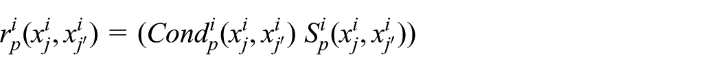
where (a)
If
The control module is modeled by a B machine that includes all the B machines of the different behaviors of the subsystem, that is

where (a)

where
Definition 6
The set of allowed distributed configurations

The vector
Definition 7
Coordinator module
The coordinator module

A distributed reconfiguration function
where (a)
The coordinator module is modeled by a B machine that includes all

where (a)

where

Discussion
The proposed DR-B formalism allows us to model a DRCS composed of n subsystems following the B method. DR-B decomposes the DRCS into a set of modules that facilitate the specification of the reconfigurable system and defines how the different modules interact and collaborate together in order to apply automatic reconfigurations and maintain coherence between the subsystems as explained in Figure 6.

Architecture of DRCS.
Verification
We propose a verification algorithm to solve the redundancy problem and to validate the different B machines (behavior, control, and coordinator). The main idea is to identify for a given configuration, the operations that should be checked. An operation should be checked only once by the Atelier B tool. So, from one configuration to another, only the new operations should be verified and also the old ones that did not respect a precedence relationship between them:
1. Algorithm. In order to ensure the correctness of a given B component, the proof obligations related to clauses initialization and operations should be verified. This task is performed by the Atelier B tool. In the following, we present the reduction algorithm of DRCS verification process in order to avoid the redundant verification of some operations.
We propose an algorithm to optimize the verification process and minimize the number of operations to be checked in B machines. The verification process determines the checked operations (L1) and those to be checked (L2) by applying the boolean function
We apply the proposed algorithm to the different B machines
2. Correctness proof of the algorithm. We prove the correctness of the proposed Algorithm 1 with the following theorem.

Theorem
Let M be a machine modeled by a set of operations

Proof
To prove the correctness of the proposed algorithm, we perform a reasoning by absurdity. Let us suppose that Algorithm 1 is not correct. That is, it does not solve the verification redundancy problem. If an

Let us assume that M is proved by Atelier B tool and described by a sequence of operations as follows

When a reconfiguration scenario is applied, the system switches to another configuration

Since the algorithm is assumed by absurdity to be not correct, from the verification of M to
We can conclude that Algorithm 1 solves the verification redundancy problem.
3. Check R-B: the implemented prototype. To simulate the verification process, we develop a prototype tool for DRCS B machines called Check R-B. The user of this tool can introduce the operations corresponding to the B machine to be verified. The tool performs a search in the file in which it is saved all the operations already checked by Atelier B tool. This list is used in order to determine the operations that have been checked and those that are not. Following this research, the Check R-B displays the checked and unchecked operations that will be forwarded to Atelier B tool to be verified. We can consider Check R-B as a module that can be added to Atelier B tool in order to minimize the number of operations to be checked.
DReconf-B approach
The proposed DReconf-B approach aims to improve the B method to model and verify DRCS, as explained in Table 2. DReconf-B covers three levels: Abstract model, refinement model, and code generation, as illustrated in Figure 7. The abstract model consists of two complementary steps: Specification and verification. In the first step, we start by defining the
Comparison between B method and the new DReconf-B approach

DReconf-B: Distributed Reconfigurable B.

DReconf-B approach for DRCS.
Presentation of FESTO and EnAS
In this article, we use the two systems FESTO and EnAS to validate the contributions of this work. They are applied by many universities for research and education purposes.
FESTO is composed of three units: Distribution, test, and processing units (Figure 8). The distribution unit is formed of a converter and a pneumatic feeder which transmits cylindrical workpieces to the test unit from a stock. The test unit consists of a detector, a tester, and an elevator. It makes tests on workpieces for height, type of material, and color. Workpieces that satisfy these tests are transmitted to the processing unit which is composed of a rotating disk, a drill machine, and a control machine. The rotating disk is composed of locations to contain and transport workpieces from the input position, to the drilling position, to the control position, and finally to the output position. In the scope of this article, we assume that the processing unit can operate with two drilling machines (Drill1 and Drill2) to perform a hole in the workpieces. Three production modes are assumed to be applied in FESTO, depending on the number of workpieces NP, that is
First production mode: If NP < C1, then we have two policies: (a) Light1. Drill1 is used only for drilling workpieces, and (b) Light2. Drill2 is used only for drilling workpieces.
Second production mode: Medium. If C1 ≤ NP < C2, then Drill1 or Drill2 is used for drilling workpieces.
Third production mode: High. If NP ≥ C2, then Drill1 and Drill2 are used simultaneously for drilling two pieces at the same time.

FESTO modular production system.
If both Drill1 and Drill2 are broken, the system is completely stopped. We should make FESTO able to switch production modes automatically according to any change in the working environment caused by errors (i.e. Drill1 error or Drill2 error) or user requirements without a halt. It is assumed that the production modes are interchangeable as shown in Figure 9.

Allowed reconfigurations of FESTO.
EnAS transports workpieces from FESTO into storing stations. It places workpieces inside tins to be closed with caps subsequently (see Figure 10). It consists of (a) a belt that moves a particular pallet containing a tin and a cap, (b) two jack stations (J1 and J2) that place new drilled workpieces from FESTO and close tins with caps, and (c) two gripper stations (G1 and G2) that remove charged tins from the belt into storing stations (ST1 and ST2). EnAS can perform three production modes, depending on the number of drilled workpieces nbpieces, tins and caps nb(tins+caps), that is
First production mode: If nbpieces/nb(tins+caps) < C1, then we have two policies: (a) Policy1. J1 places and closes, G1 removes into St1 and (b) Policy2. J1 places, J2 closes, G2 removes into St2.
Second production mode: Policy3. If C1 ≤ nbpieces/nb(tins+caps) < C2, then J1 places and closes, G2 removes into St2 or J1 places, J2 closes, G1 removes into St1.
Third production mode: Policy4. If nbpieces/nb(tins +caps)≥C2, then J1 places, J2 places and closes, G2 removes the tin (with two pieces) into St2.

EnAS demonstrator.
The system is completely stopped if both J1 and J2 are broken. We should make EnAS able to switch policies automatically according to any change in working environment caused by errors (i.e. J1/G1 Error or J2/G2 Error) or user requirements without a halt. It is assumed that policies are interchangeable as shown in Figure 11.

Allowed reconfigurations of EnAS.
The two systems FESTO and EnAS coordinate the work to guarantee the correctness and safeness of the whole system. When a local reconfiguration is allowed to be applied in one of them, then the other system should have a proper respond to react to the planned reconfiguration. The behavior modes Light1, Light2, and Medium of FESTO can cohere with Policy1, Policy2, and Policy3 of EnAS and High of FESTO requires Policy4 of EnAS and vise versa.
Application of the DReconf-B approach
We apply the proposed DReconf-B to a DRCS composed of two subsystems,
Abstract model. We present the abstract model steps of DRCS composed of FESTO and EnAS. (a) Specification. We define the behavior, control, and coordinator modules of the specification phase of FESTO and EnAS subsystems.
FESTO and EnAS behaviors modules
According to the three production modes, FESTO behavior module is modeled by eight machines that specify the four policies, that is

Each machine is described by a sequence of ordered operations as explained in Figure 12, that is
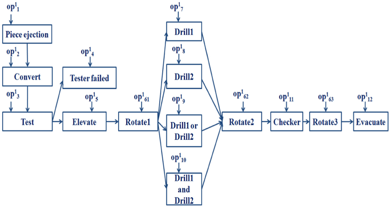
Working process of FESTO.
The default initial production mode is Light1 that can be described by the combination of
EnAS can perform three types of behavior modes according to the production rate. EnAS behavior module is modeled by 12 machines that specify the four policies, that is
Each EnAS machine is described by a sequence of ordered operations as described in Figure 13, that is

Working process of EnAS.
The default initial production mode is Policy1. It is described by the combination of
FESTO and EnAS control modules
We define the control modules of the two subsystems FESTO and EnAS. FESTO can apply nine different reconfiguration functions as explained in Figure 9. The FESTO control module is given by

Let us assume that FESTO is in the production mode Light1 when the user requests to change the production mode to Medium. If

Then,
where a1.MF2 (resp., d1.MF5) represents the instance of the machine

Let us assume that EnAS is in the production mode Policy1 when the user requests to change the production to Policy3. If

Then,
where h1.ME1 (resp., n1.ME6) represents the instance of the machine
In order to model the coordination between the two subsystems FESTO and EnAS, we apply the DR-B formalism to define
Coordinator module
According to Figures 9 and 11, we define as shown in Figure 14, a state machine composed of 10 states which correspond to a specific distributed configuration. Each transition means a reconfiguration of the system from a distributed configuration to another one. The set of allowed distributed configurations is given by


Coordinator specification of FESTO and ENAS.
FESTO and EnAS can apply 58 different distributed reconfiguration functions as shown in Figure 14 to respond to user requests or occurred faults. The coordinator module is represented as follows

Let us assume that FESTO is in Light1 when the user requests to change the production mode to Medium and EnAS is in Policy1 when the user requests to change the mode to Policy3. If
where MF2_to_MF5 (resp., ME1_to_E6) represents the call of the operation of the included machine FESTO_Control_Machine (resp., EnAS_Control_ Machine) that switches the system from Light2 to Medium (resp., from Policy1 to Policy3).
(b) Verification. The proof obligations of B machines corresponding to FESTO and EnAS subsystems were proved by the Atelier B tool and the invariants were preserved by the operations. We note that the machines
As shown in Figure 15, the previous five operations and the last four operations of

Verification of RCS FESTO.
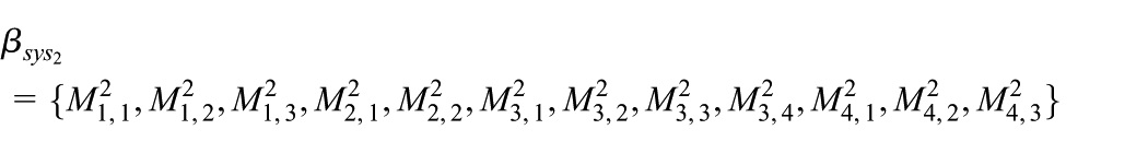
As shown in Figure 16, the first five and the four last operations instances corresponding to

Verification of FESTO control module.
As shown in Figure 17, from the distributed configuration
(c) Refinement model. Once the abstract model is complete and validated, the next step consists in refining the abstract solution into a concrete one.
(d) Code generation. The C code is automatically generated by the Atelier B tool from the last concrete one.

Verification of DRCS composed of FESTO and EnAS.
Evaluation of performance and comparative study
We evaluate the DReconf-B approach for modeling and verification of dynamic, automatic, and flexible DRCS. The idea is to count the maximum number of operations to be checked when a reconfiguration scenario is applied. We denote, respectively, by
If we apply the Check R-B tool to verify DRCS, then

If we do not apply the Check R-B tool to verify DRCS, then

The gain of our approach is to reduce the number of checked operations, that is

The FESTO behavior module is modeled by eight B machines. We assume that the verification of FESTO B machines is performed in the following order
Verification result of FESTO behavior B machines.

The FESTO control B machine is characterized by nine operations where each one uses 10 instances of operations from
Verification result of FESTO control B machine.

The coordinator B machine consists of 58 operations. Table 5 depicts the verification result of only the 10 operations that model the mentioned distributed configurations. For the verification of
Verification result of distributed configurations.

If we use the B method to model RCS (resp., DRCS), then we obtain only one B machine which describes all the possible configurations (resp., distributed configurations) of RCS (resp., DRCS). Figure 18(a) (resp., Figure 18(b)) concerns the verification of FESTO behavior B machines (resp., FESTO control B machine). Figure 18(c) is about the verification of the different distributed configurations of the coordinator B machine. The curves represent the comparison between the verification process using B method, DReconf-B without Check R-B and DReconf-B using Check R-B. We note that the number of checked operations decreases gradually until reaching the value zero when the Check R-B tool is used and stagnates when we use the B method. Furthermore, we remark that the gain in number of checked operations reaches 60% value for the FESTO control B machine and 78.25% value for the coordinator B machine. Therefore, we can conclude that the proposed DReconf-B approach is appropriate for modeling and verification of dynamic, automatic, and flexible DRCS.

Verification of B machines. (a) Verification of FESTO behavior machines, (b) verification of FESTO control machine, and (c) verification of B coordinator machine.
We compare in Table 6 the proposed DReconf-B approach with the related works in the literature. We can conclude that the originality of DReconf-B lies in the using of B formal method to model and verify dynamic and flexible DRCS. DReconf-B defines a multi-agent architecture which aims to ensure flexibility and agility of a DRCS, in order to adapt them to their environment. Also, it optimizes the verification by reducing the number of B operations machines to be checked using the Atelier B and the implemented Check R-B tool.
Comparative study.

MAS: multi-agent system; DRCS: distributed reconfigurable control system; DR-B: Distributed Reconfigurable B; MDD: model-driven development; UML: unified modeling language.
Conclusion
In this research article, we propose a novel DReconf-B approach aiming to extend the B method to model and verify dynamic, automatic, and flexible DRCS. We define a multi-agent architecture which affects to each subsystem a reconfiguration agent that applies local automatic reconfigurations, and a coordination agent that manages subsystems to assure safe and suitable reconfigurations. DReconf-B covers three levels: Abstract model, refinement model, and code generation. The first level is composed of two complementary steps: Specification and verification. The first step models the agents according to R-B and DR-B formalisms. The second verifies DRCS using the Atelier B and the developed Check R-B tools to decrease the checking of different redundancies in different configurations that share redundant B machines operations. The second level refines the abstract model into another concrete one and the third level translates automatically all the concrete implementations into C code. We apply the paper’s contributions to the two benchmark production systems FESTO and EnAS.
In the future work, we plan to focus on the modeling of DRCS harmonized by several multi-event coordination agents. Also, we plan to develop a graphical tool that allows the efficient modeling and verification of DRCS using the DReconf-B approach.
Footnotes
Appendix 1
Handling Editor: ZhiWu Li
Declaration of conflicting interests
The author(s) declared no potential conflicts of interest with respect to the research, authorship, and/or publication of this article.
Funding
The author(s) received no financial support for the research, authorship, and/or publication of this article.